
Control Circuit
Index 225
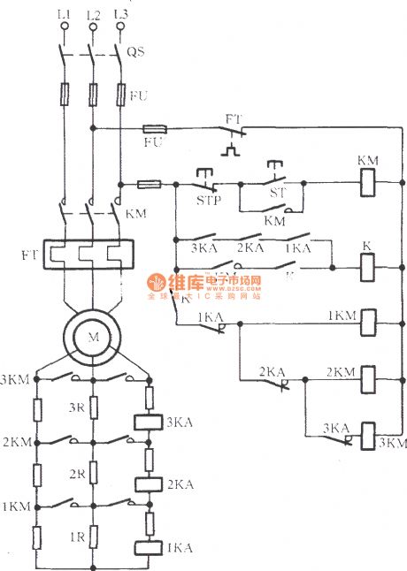
Wound rotor induction motor ultilizing current variation starting circuit
Published:2011/7/5 3:49:00 Author:John | Keyword: Wound rotor, induction motor
View full Circuit Diagram | Comments | Reading(1774)
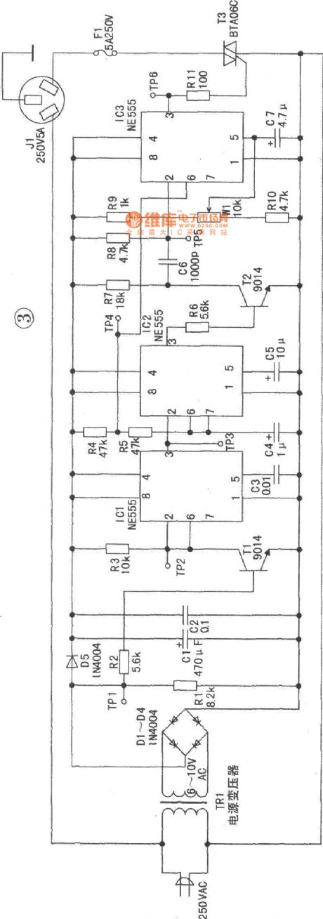
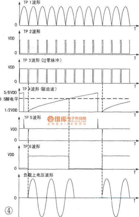
Silicon controlled zero-crossing trigger voltage regulator circuit
Published:2011/7/5 19:48:00 Author:Christina | Keyword: Silicon controlled, zero-crossing, trigger, voltage regulator
View full Circuit Diagram | Comments | Reading(1136)
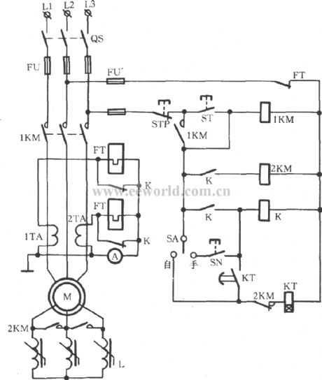
wound rotor induction motor serial reactor step-down starting circuit
Published:2011/7/4 23:49:00 Author:John | Keyword: wound rotor, induction motor, reactor
View full Circuit Diagram | Comments | Reading(2431)
Thermal relay overload protection circuit
Published:2011/7/5 4:04:00 Author:John | Keyword: Thermal relay
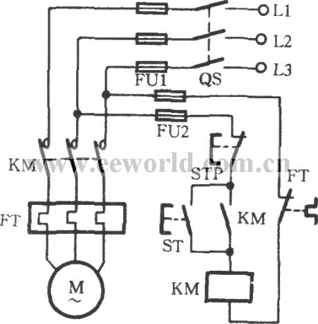
Thermal relay overload protection circuit can be applied to avoid the failure, which is as shown. FT is the thermal relay in the string for the circuit. When motor M is overloaded, internal heating elements of FT are heated. Then the bimetal pieces bend to promote the FT’s normally closed contacts to disconnect. Thus, the AC power contactor KM coil is off. The main contact KM is off to stop the motor M. at the end, the overload failure of the winding burn can be effectively eliminated. After the overload failure being removed, Reset button of the thermal relay is pressed as well as the starting button ST. Finally, the motor can start again.
(View)
View full Circuit Diagram | Comments | Reading(6171)
Vertical mill electrical control circuit
Published:2011/7/5 0:03:00 Author:John | Keyword: Vertical mill
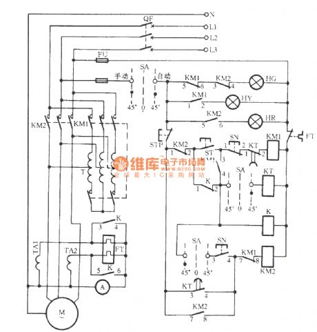
The button ST is pressed to induct the KM1 coil circuit. When the pin 5-6 of KM1 is disconnected, HG is off; and when the pin 1~2 is connected, yellow light HY lights. This indicated that it is starting. The pin 7-8 of KM1 is disconnected to prevent KM2 from being powered under accidental circumstances. Thus, the interlock between KM1 and KM2 has been achieved. When the contact 3-4 of KM1 is closed, KM1 is self-locked. This is able to lead the timing relay KT to start to work. (SA’s contacts are connected), but also to close the middle relay K by electric pull. Then the contact 3 ~ 4 and contact 5 ~ 6 both close. As a result, the heating element in the hot relay circuit is in short, thus preventing motor M from FT’s malfunction while staring with high current.
(View)
View full Circuit Diagram | Comments | Reading(4102)
freezer and cooling pump interlock control circuit
Published:2011/7/5 0:07:00 Author:John | Keyword: freezer, cooling pump, interlock
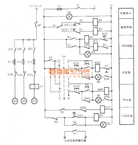
The freezer and cooling pump interlock control circuit is as shown. It can be started through starting frozen pump, cooling pump and opening the freezer boot process. It can be stopped by the reverse process
(View)
View full Circuit Diagram | Comments | Reading(2290)
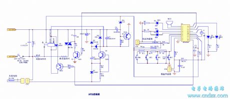
Delicate automatic rice cooker 2
Published:2011/7/5 0:38:00 Author:John | Keyword: rice cooker
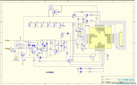
PDF for related components can be downloaded.
BT13480508550S3P2289015
(View)
View full Circuit Diagram | Comments | Reading(1555)
Delicate automatic rice cooker 1
Published:2011/7/5 0:40:00 Author:John | Keyword: automatic rice cooker
PDF for related components can be downloaded.
BT13480508550HT46R47 (View)
View full Circuit Diagram | Comments | Reading(2996)
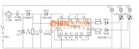
Single-switch multiple-light control circuit (3)
Published:2011/7/1 3:16:00 Author:Ecco | Keyword: Single-switch , multiple-light , control
The chart shows the multiple-light circuit which uses single button SB to control, and it can light a group or several groups of groups by the numbers of presssing key, and there is a total of seven states to choose, and the control circuit is suitable for the living room chandelier. VTH1 ~ VTH3 can use MAC94A4 small plastic Triac.
(View)
View full Circuit Diagram | Comments | Reading(910)
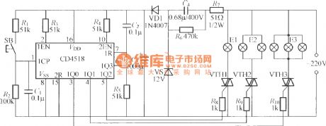
Single-switch multiple-light control circuit (2)
Published:2011/7/1 3:04:00 Author:Ecco | Keyword: Single-switch, multiple-light , control
In the circuit shown as the chart, only a power switch S can controll E1, E2 and E3, so it is suitable for the living room chandelier. When S is off, all the lights are off; the first time to connect the S, only the E1 is lit; disconnecting and connecting S in a short time, E1 and E2 are lit; disconnecting and connecting S again, E1 and E3 are lit; disconnecting and connecting S again, all E ~ E3 are lit.
(View)
View full Circuit Diagram | Comments | Reading(991)
Pendant Light Controller (1)
Published:2011/7/3 2:43:00 Author:Sue | Keyword: Pendant Light, Controller
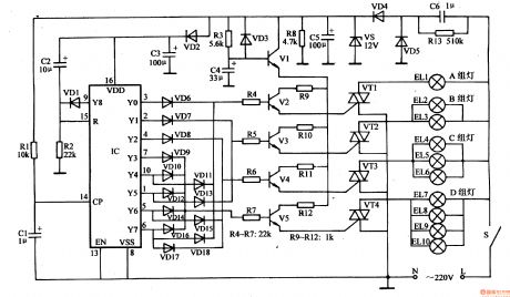
The 220v voltage will generate +12v voltage after reduction, rectification, stablization. The voltage will provide IC with working power. The other circuit will provide V2-V5 with working voltage.
IC's pin 14 will beconnected to +12V power. Every time S is connected, the positive pulse will be put on IC's pin 14, which will make IC have a count. When S is connected and disconnected intermittently, IC's Y0-Y8 will output high level which will make the thyristor connected. Then the lights will have 8 different illumination states. (View)
View full Circuit Diagram | Comments | Reading(745)
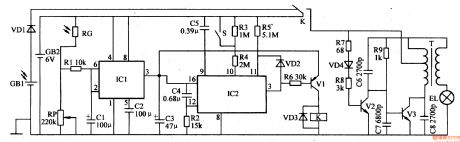
Light-Operated Neon Light (2)
Published:2011/7/3 3:01:00 Author:Sue | Keyword: Light-Operated, Neon, Light
The 220v working voltage will provide IC1 with +8.4 working voltage after reduction, stablization, rectification and filtration.
In the daytime, RG will have a low resistance value because of light, IC1's pin 2 and pin 6 will have high level. Pin 3 will output low level. VT is disconnected. HL doesn't work.
When it is dark, RG will have a high resistance value because of lack of light. IC1's pin 2 and pin 6 will have low level. IC2 will begin to work and begin to count. Its pin 3 will output low level. V and VT are disconnected. When time is over, IC2's pin 3 will become high level. V and VT are connected. HL stops working. (View)
View full Circuit Diagram | Comments | Reading(721)
Light-Operated Neon Light (1)
Published:2011/7/3 2:55:00 Author:Sue | Keyword: Light-Operated, Neon, Light
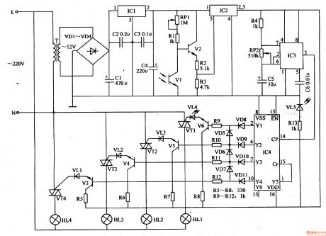
The 220v voltage will provide C4 with +12v working voltage after reduction, rectification, filtration and stablization.
In the daytime, V1 has a high resistance value because of the light, V2 is disconnected. IC2's inner switch is disconnected. IC3 and IC4 will have no working voltage. VT1-VT4 are disconnected. HL1-HL4 are not illuminated.
When it is dark, V1 has a low resistance value because of lack of light. V2 is connected. IC2's pin 5 has a high level. Its inner switch will be connected. Pin2 and pin 3 will output +12v voltage. IC3 and IC4 will begin to work. (View)
View full Circuit Diagram | Comments | Reading(728)
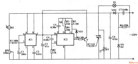
Light-Operated Streetlight (16)
Published:2011/7/1 6:38:00 Author:Sue | Keyword: Light-Operated, Streetlight
In the daytime, GB will be charged. RG will have a low resistance value which will make IC1's pin 2's and pin 6's voltages higher than 2Vcc/3. IC1's pin 3 will output low level. IC2 and V1 don't work. K is released and EL is not illuminated.
When it is dark, RG has a larger resistance value which will make IC1's pin 2's and pin 6's voltage become lower. When the voltage is lower than Vcc/3, IC1's inner circuit will be reversed. Its pin 3 will have high level. IC2 and V1 will begin to work. Then pin 3 will output low level which will makes V1 connected. K is connected. Then ELA will be illuminated. (View)
View full Circuit Diagram | Comments | Reading(560)
Light-Operated Streetlight (15)
Published:2011/7/1 6:30:00 Author:Sue | Keyword: Light-Operated, Streetlight
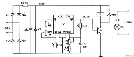
The 220v voltage will provide the light-operated circuit with +12v working voltage after rectification, filtration and stablization.
In the daytime, RG1 and RG2 will have low resistance values. IC's S1 will output low level. R1 will output high level. Q1 will output low level. V is disconnected and K is released. EL is not illuminated.
When it is dark, RG1 and RG2 will have higher resistance values. IC's S1 will output high level. R1 will output low level. Q1 will output high level. V is connected and K is connected. EL will be illuminated. (View)
View full Circuit Diagram | Comments | Reading(539)
Elevator motor overspeed controller
Published:2011/7/1 1:30:00 Author:Nicole | Keyword: elevator, motor, overspeed controller
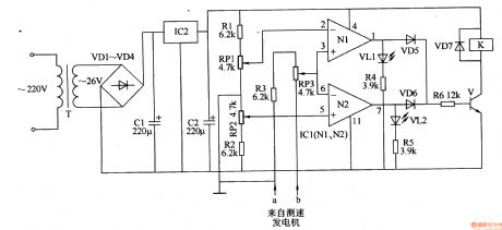
The elevator motor overspeed controller circuit is composed of power supply circuit, LED indication circuit and speed measurement control circuit, it is shown in the figure 8-66.
The power supply circuit is made of power transformer T, rectifier diodes VD1-VD4, filter capacitors C1, C2 and there terminals steady voltage integrated circuit IC2.
The LED indication circuit consists of LED VL1, VL2 and resistors R4, R5.
The speed measurement control circuit is composed of resistors R1-R6, potentiometers RP1, RP2, operation amplifier integrated circuit IC1(N1, N2), diodes VD5-VD7, transistor V and relay K.
(View)
View full Circuit Diagram | Comments | Reading(2171)
Turn-off control circuit
Published:2011/7/4 20:54:00 Author:Christina | Keyword: Turn-off, control circuit
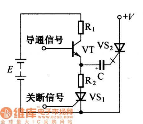
The conduction and turn-off control circuit of the shut-off thyristor is as shown in the figure. When the conduction trigger signalis addedto the base of the semiconductor transistor VT, the VT conducts through the thyristor VS2 which is triggered by the capacitance C. At the same time, the power supply E charges the C through R1. When the turn-off positive pulse comes, the trigger transistor VS1 conducts, the capacitor C discharges through the R2, VS1, VS2(K-G). Because the voltage of the two ends of capacitor C can not change, so the circuit adds the negative pulse to the turn-off thyristor control electrode to turn off the VS2.
(View)
View full Circuit Diagram | Comments | Reading(692)
Motor electronic governor controller 7
Published:2011/6/30 22:50:00 Author:Nicole | Keyword: motor, electronic governor controller
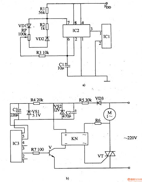
The motor electronic governor controller circuit is composed of wireless remote control transmitting circuit and wireless remote control receiving control circuit, it is shown in the figure 8-64.
The wireless remote control transmitting circuit is made of micro-power wireless remote control transmitting integrated circuit module IC1, time base integrated circuit IC2, diodes VD1, VD2, resistors R1-R3, potentiometer RP and capacitor C1.
The wireless remote control receiving control circuit consists of micro-power wireless remote control receiving integrated circuit module IC3, steady voltage diode VS1, VS2, resistors R4-R7, diode VD3, transistor V, solid state relay KN(SSR) and thyristor VT.
(View)
View full Circuit Diagram | Comments | Reading(1054)
Motor voltage reducing starter 2
Published:2011/6/29 20:54:00 Author:Nicole | Keyword: motor, voltage reducing starter
The motor voltage reducing starter circuit is composed of regulated power supply circuit, delay control circuit and control implement circuit, it is shown in the figure 8-56.
The regulated power supply circuit is made of fuses FU1, FU2, stop button S1, capacitors C1, C2, heat relay KR's normally closed contact, resistors R1, R2 and steady voltage diode VS.
The delay control circuit consists of starter control button S2 (S2-1-S2-3), capacitor C3, potentiometer RP, transistor V, TRIAC VT and intermediate relay KA.
When stop button S1 is pressed, the whole circuit is power failure and it stops working.
(View)
View full Circuit Diagram | Comments | Reading(633)
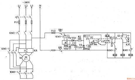
Motor voltage reducing starter 1
Published:2011/6/29 20:24:00 Author:Nicole | Keyword: motor, voltage reducing starter
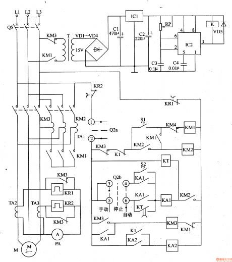
The motor voltage reducing starter is composed of voltage reducing starter control circuit and protection circuit, it is shown in the figure 8-55.
The voltage reducing starter control circuit is made of starter button S1, master controller(Q2a, Q2b), AC contactor KMl-KM3, intermediate relay KA1, KA2, time relay KT, autotransformer TA1.
The protection circuit consists of power transformer T, diodes VDl-VD5, capacitors C1-C3, there terminals steady voltage integrated circuit IC1, potentiometer RP, time base integrated circuit IC2 and relay K.
TA2, TA3 are current transformers, KR1 and KR2 are heat relays, QS is circuit breaker.
(View)
View full Circuit Diagram | Comments | Reading(751)
| Pages:225/312 At 20221222223224225226227228229230231232233234235236237238239240Under 20 |
Circuit Categories
power supply circuit
Amplifier Circuit
Basic Circuit
LED and Light Circuit
Sensor Circuit
Signal Processing
Electrical Equipment Circuit
Control Circuit
Remote Control Circuit
A/D-D/A Converter Circuit
Audio Circuit
Measuring and Test Circuit
Communication Circuit
Computer-Related Circuit
555 Circuit
Automotive Circuit
Repairing Circuit