
Control Circuit
Index 236
555 fridge automatic temperature controller circuit
Published:2011/6/16 2:31:00 Author:TaoXi | Keyword: 555, fridge, automatic, temperature controller
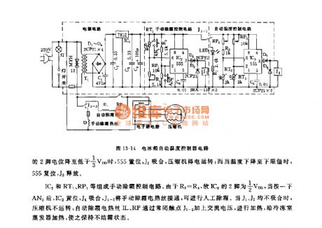
As the figure 13-14 shows, the fridge automatic temperature controller circuit is composed of the step-down voltage-stabilizing circuit, the automatic temperature control circuit, the manual defrosting control circuit and the relay control circuit. This circuit has all functions of the Toshiba GR204E automatic defrosting type automatic temperature control circuit.
The step-down voltage-stabilizing circuit is the +12V voltage source of the controller. The IC3(555) is connected into the bistable operating mode, the maximum temperature detection circuit is composed of the RP3 and RT3, the minimun temperature detection circuit is composed of the RP2,R2 and RT2, the RT2 and RT3 use the NTC negative temperature coefficient thermistor. When the temperature of fridge increases, the resistance of RT reduces.
(View)
View full Circuit Diagram | Comments | Reading(1355)
555 sound and light synchronous touch-bell metronome circuit
Published:2011/6/15 8:57:00 Author:TaoXi | Keyword: 555, sound, light, synchronous touch-bell, metronome
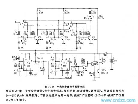
As the figure 14-34 shows, the metronome is composed of two beat generators, the bell sound amplification circuit and the luminous display circuit.
The multivibrators is composed of the IC1, RP1, R14, C4 and the IC2, R16, R17, C6 respectively, the oscillation frequency of IC1 is f1=1.44/(RP1+2R14)C4, it is in the range of 1Hz~100Hz. The oscillation frequency of IC2 is f2=1.44/(R16+2R17)C6, it is about 1000Hz. The duty ratio of IC1's oscillation square-wave can be very large, if the resistance of RP1 is 100kΩ, f1 is about 2Hz, the duty ratio is about 99%.
The oscillation square-wave which is output by the IC2 adds to VT4 through C7 and R18. When the positive differential pulse of IC1 comes, the two channels of signals act on VT4 at the same time to make the jet current of VT4 very large.
(View)
View full Circuit Diagram | Comments | Reading(1053)
555 sound and light signal metronome circuit
Published:2011/6/15 8:38:00 Author:TaoXi | Keyword: 555, sound, light, signal, metronome
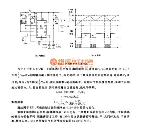
As the figure 14-33 shows, this circuit is composed of a pair of time base circuit 556, and the two time base circuits are connected into two multivibrators. One multivibrator is used to produce the 1kHz oscillation square-wave, this oscillation square-wave is output from pin-9 to encourage the piezoelectric ceramics to send out the sound. Another multivibrator is used to produce the low frequency square-wave to modulate the 1kHz square-wave signal.
After the switch K is closed, pin-6's capacitance C1 of the first oscillator charges it through RP1, when the voltage of VC1 is 2/3VDD, the circuit's output port pin-5 has the low electrical level. At the same time, because the disrharge tube of the integrated block is conducted, so the capacitor C1 charges through R2, when the voltage of C1 is 1/3VDD, the circuit turns to output the high electrical level.
(View)
View full Circuit Diagram | Comments | Reading(855)
555 TV automatic shutdown controller circuit
Published:2011/6/15 3:13:00 Author:TaoXi | Keyword: 555, TV, automatic, shutdown, controller
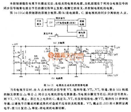
The principle block diagram of the controller is as shown in figure 14-15(a), figure(b) is the circuit. The C1 is connected with the A point of the TV's sync separation stage.
When there is the TV signals, the sync signal from point A conducts the VT1, then VT2 and VT3 conduct to set the trigger which is composed of 555, the JB and J1 closes to turn on the TV's power supply; when the TV program is over, the sync signal disappears, so VT2 and VT2 cut off. The charged C2 discharges through the emitters of R5 and VT3 to keep the VT3 in the conduction state for 10 seconds, so that we can avoid the shut-down phenomenon which is caused by the programme-delivery intermittent or the replacing. After the VT3 cuts off, pin-6 of 555 has the high electrical level to reset 555, JB releases to cut off the TV's power supply.
(View)
View full Circuit Diagram | Comments | Reading(756)
Motor Operation Control Circuit of LT1014
Published:2011/6/25 22:44:00 Author:Michel | Keyword: Motor, Operation , Control Circuit
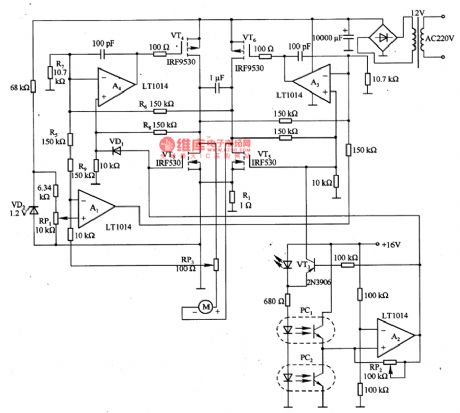
The aboved picture is motor operation control circuit compsoed of LT0140 etc.Motor speed voltage is set by middle tap of potentiometer RP1.In order to make the motor speed stable, RP3 adjusts the positive feedback voltgae from current detection resistance R1 is inversely proportional to the current and A1 adds the feedback voltage and speed setting voltage together.The best RP3 adjustment can completely offset the motor parasitic resistance, so that motor torque-speed characteristics are hard.Motor speed control performance does not depend on mechanical loading, but driving circuit voltage. (View)
View full Circuit Diagram | Comments | Reading(1092)
The multi-way alarm monitor circuit
Published:2011/6/28 20:28:00 Author:qqtang | Keyword: multi-way, alarm monitor
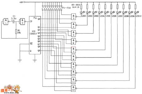
The multi-way alarm monitor circuit is shown in the figure. It consists of the integrated circuits of CD401 and CD4017, and it is used in indicator alarm and monitoring. This circuit can do circle monitoring to 10 spots, once the burglary happened at on spot, the LED monitoring station fixed in the duty room would get corresponding alarm signal.
(View)
View full Circuit Diagram | Comments | Reading(696)
The metal door prying resistant alarm circuit
Published:2011/6/28 20:41:00 Author:qqtang | Keyword: prying resistant, alarm circuit
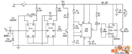
The metal door prying resistant alarm circuit is shown in the circuit. This circuit consists of the CD4528、NE555 and KD9561 integrated circuit and other external elements. The circuit control is sensitive and it's adjustable, it's also reliable and low-cost.
(View)
View full Circuit Diagram | Comments | Reading(692)
The breeze ceiling fan temperature control circuit
Published:2011/6/28 21:12:00 Author:qqtang | Keyword: ceiling fan, temperature control
In the figure is the breeze ceiling fan temperature control circuit which consists of the temperature detection circuit and step-down rectifier power supply. In the circuit, the power supply provides with VDD=+5V DC voltage for the control circuit. The temperature detection control circuit is the dual steady trigger whose core is composed of IC(555), R5, R7, W1 and R6, and R6 and R7 is adopted with the NTC thermistor as the temperature detection element.When the environment temperature is rising, the resistance of R6 and R7 is falling down, which makes the IC to be reset because the LEV of 2-pin is dropping to 1/3VDD, and 3-pin is outputting a high LEV.
(View)
View full Circuit Diagram | Comments | Reading(1882)
The precise temperature control circuit of temperature/frequency converter
Published:2011/6/28 21:29:00 Author:qqtang | Keyword: temperature control, temperature/frequency converter

In the figure is the precise temperature control circuit of temperature/frequency converter, which consists of the temperature sensor B, multi-resonance oscillator, audio decoder and relay, etc. The oscillator consists of IC1(555), R1, C1 and the temperature sensor, whose oscillating frequency is fc=1.44/(Rl+2RB)C1. As RB changes with the temperature, so fs also changes with the temperature. The audio decoder is adopted with the audio decoding integrated circuit IC2(LM567) with phase-lock, whose central frequency is fo=1/1.1Rw1C4, by adjusting W1, fo is the frequency of setting temperature.
(View)
View full Circuit Diagram | Comments | Reading(1035)
The electric oven temperature control circuit of single phase controllable silicon zero passage trigger
Published:2011/6/28 21:55:00 Author:qqtang | Keyword: electric oven, temperature control, controllable silicon
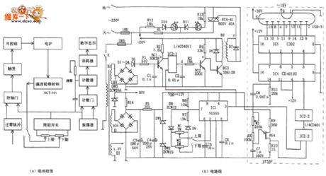
In the figure is the electric oven temperature control circuit of single phase controllable silicon zero passage trigger. This temperature control device consists of the detecting temperature control circuit, zero passage detection circuit, period switch, trigger control and digital display, etc. It is often used with XCT-101 temperature controller, which can monitor the 6~8kW electric oven temperature of single phase controllable silicon zero passage trigger, both temperature rising and dropping are adjusted within 1%~99%. The temperature control device XCT~101 detects the oven internal temperature with thermocouple and compares the real temperature with the preset temperature.
(View)
View full Circuit Diagram | Comments | Reading(3000)
The incubation temperature control circuit
Published:2011/6/28 22:11:00 Author:qqtang | Keyword: incubation, temperature control
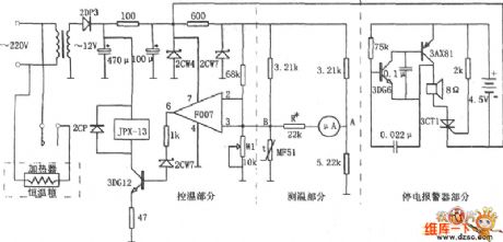
In the figure is the incubation temperature control circuit. This circuit consists of the temperature test circuit, temperature control circuit and power-off alarm circuit, etc.the temperature circuit is a non-equilibrium type bridge, which is indicated with a 50μA meter. One arm of the bridge is a sensitive thermistor MF51 which has backward temperature coefficients. As the temperature in the incubation box changes, the resistance of MF51 is also changing, the LEV between A and B of the corresponding bridge is changing, too. The temperature change is reflected by the pointer of the 50ttA meter.
(View)
View full Circuit Diagram | Comments | Reading(1479)
Bean sprout machine thermostat controller circuit diagram
Published:2011/6/14 3:11:00 Author:Lucas | Keyword: Bean sprout machine, thermostat controller
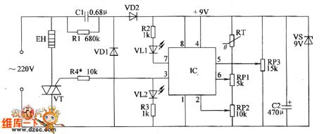
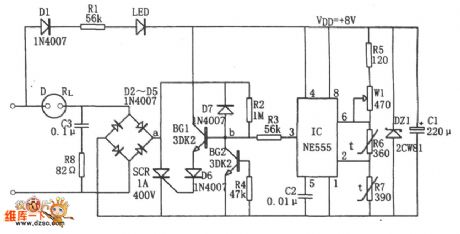
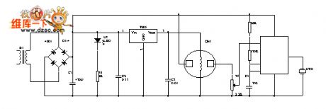
The bean sprout machine thermostat controller circuit is composed of the power supply circuit and temperature detection control circuit, and the circuit is shown as the chart. The power supply circuit is composed of the drain resistor R1, rectifier diodes VD1, VD2, power regulator diode VS, buck capacitor C1, filter capacitor C2. Temperature detection control circuit is composed of the thermistor RT, potentiometers RP1 ~ RP3, resistors R2 ~ R4, VT and heating wire EH. AC 220V voltage bucked by C1, rectified by VD1 and VD2, stabilized by VS and filtered by C2 can provide +9 V voltage for IC. R1 ~ R4 select 1/2W metal film resistors. RP1 ~ RP3 use synthetic membrane potentiometers. VD1 and VD2 select 1N4007 silicon rectifier diodes.
(View)
View full Circuit Diagram | Comments | Reading(2153)
Bean sprouts automatic watering thermostats circuit diagram
Published:2011/6/14 3:03:00 Author:Lucas | Keyword: Bean sprouts , automatic watering , thermostats
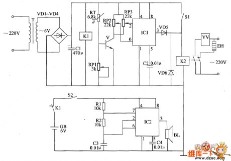
The bean sprouts automatic watering thermostats circuit is composed of the power supply circuit, temperature detection control circuit and power failure alarm circuit, and the circuit is shown as the chart. Temperature detection control circuit is composed of the thermistor RT, potentiometers RP1 ~ RP3, transistor V, time-base integrated circuit IC1 and capacitor C2, diodes VD5, VD6, relay K2 and the control switch S1 . Power failure alarm circuit consists of the relay K1, switch S2, resistors R1, R2, capacitors C3, C4, and speaker BL and the time-base integrated circuit IC2. R1 and R2 use 1/4W carbon film resistors or metal film resistors. RP1 ~ RP3 use small organic solid potentiometers or variable resistors. RT chooses the thermistor resistor with negative temperature coefficient.
(View)
View full Circuit Diagram | Comments | Reading(989)
Greenhouse ground hotline controller circuit diagram 2
Published:2011/6/14 5:20:00 Author:Lucas | Keyword: Greenhouse, ground hotline , controller
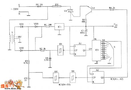
The greenhouse ground hotline controller circuit is composed of the power supply circuit and heating control circuit, and the circuit is shown as the chart. Power supply circuit is composed of the fuse FU, power transformer T, rectifier diodes VD1 ~ VD3, resistor R1, three-terminal voltage regulator integrated circuit IC and the filter capacitor C1. Heating control circuit is composed of the resistors R2 ~ R5, capacitor C2, voltage regulator diode VS, Schmitt trigger NAND gate integrated circuit IC2 (D1 ~ D3), JK flip-flop integrated circuit IC3 (A1, A2), count / pulse divider IC IC4, selector switch S, transistor V, thyristor VT and ground hotline EH. R1 ~ R3 and R5 select 1/2W metal film resistors.
(View)
View full Circuit Diagram | Comments | Reading(1261)
Greenhouse ground hotline controller circuit diagram 1
Published:2011/6/14 5:15:00 Author:Lucas | Keyword: Greenhouse, ground hotline, controller
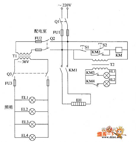
The greenhouse ground hotline controller circuit is composed of the power supply control circuit, working status indicator circuit and low voltage lighting circuit, and the circuit is shown as the chart. Control circuit is composed of the knife switch Q1, fuse FU1, control buttons S1, S2, AC contactor KM and ground hotline EH. Working status indicator circuit consists of the power transformer T1, lights HL1, H12, and the control contacts KM3, KM4 of KM. Low-voltage lighting circuit is composed of the power transformer T1, knife switches Q2, 03, fuses FU2, FU3 and lighting lamps EL1 ~ EL4. KM chooses CDC10-5 220V AC contactor. Q1 chooses HK2-30 Q1 knife switch; Q7 and Q3 use HK1-15 knife switches.
(View)
View full Circuit Diagram | Comments | Reading(1220)
Intelligent lock control balcony alarm bell circuit diagram
Published:2011/6/20 6:36:00 Author:Lucas | Keyword: Intelligent, lock control , balcony , alarm bell
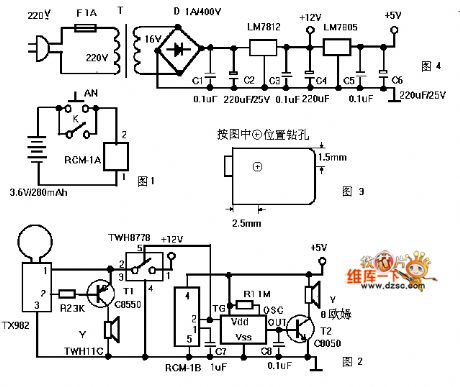
Figure 1 is a transmitter circuit which is installed at the gate. AN is the doorbell button, and K is the lock control switch; when all the family goes out and locks the check-lock for insurance, the K connected automatically to play the role of fortification. When people press the AN or connect K, RCM-1A will launch 250 ~ 300MHz radio wave by modulation, Figure 2 is a receiver circuit, which is installed in the balcony ceiling, and RCM-1B can receive the modulation radio waves and pin 2 output is in high level, thereby it triggers the language IC to work.
(View)
View full Circuit Diagram | Comments | Reading(1211)
Battery charging protection circuit composed of the PTC component and the over-voltage protection component
Published:2011/6/28 19:08:00 Author:TaoXi | Keyword: Battery charging, protection circuit, PTC component, over-voltage protection component
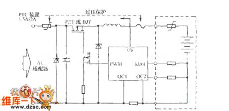
The PTC component and the over-voltage protection component harmonize to complete the following jobs: 1.Supply the current protection for the FET which might be damaged and the battery's excessive current. 2. The PTC limits the over-current which is produced by the forward direction conduction of the Zener diode. 3. Limit the conduction current when the over-voltage component is protecting the voltage overload.
(View)
View full Circuit Diagram | Comments | Reading(772)
Gas / smoke alarm circuit diagram
Published:2011/6/14 3:29:00 Author:Lucas | Keyword: Gas, smoke , alarm
The gas / smoke alarm circuit is shown in Figure, and it is composed of the power supply circuit, sensor and multivibrator. One way of the 220V mains electricity bucked by the transformer, rectified by full bridge, filtered by capacitor and through the three-terminal voltage regulator can provide +S V voltage for the gas sensor, the other way can directly supply multivibrator speaker. Sensor uses QM-N 5 or QM 211 type. It is a relatively strong universal gas sensor which is suitable for the smoke and fire caused by natural gas, coal gas, LPG, gasoline, carbon monoxide, hydrogen, alkanes, alcohols, and wood, paper; cloth, hair products, rubber products, plastic products and oil and so on.
(View)
View full Circuit Diagram | Comments | Reading(955)
Two-way diode trigger circuit
Published:2011/6/27 8:50:00 Author:Christina | Keyword: Two-way diode, trigger circuit

The application two-way diode trigger & two-way thyristor circuit is designed as one kind of typical and common trigger circuit, as the figure shows. In general the two-way diode is in the high impedance cut-off state. Only when you add the voltage (both positive and negative) to the two-way diode, and this voltage is higher than the breakdown voltage of the two-way diode, the two-way diode will be punctured and be conducted. The general breakdown voltage of the two-way diode is tens of volts.
When the circuit is connected with the AC city electricity, the AC city electricity will charge to the capacitance C through RL, RP, R2.
(View)
View full Circuit Diagram | Comments | Reading(1090)
Irrigation motor automatic protector circuit diagram 1
Published:2011/6/14 4:15:00 Author:Lucas | Keyword: Irrigation motor, automatic protector
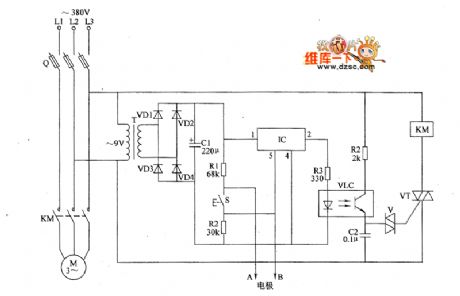
The irrigation motor automatic protector circuit is composed of the power supply circuit and the detection / protection control circuit, and the circuit is shown as the figure. Power supply circuit is composed of the power transformer T, rectifier diodes VD1 ~ VD4 and filter capacitor C1. Detection / protection circuit is composed of the detection electrodes A, B, Start button S, resistors R1 ~ R4, capacitor C2, optocoupler VLC, bi-directional trigger diode V, thyristor VT, electronic switch IC IC and AC contactor KM. AC 380V voltage is bucked by T, rectified by VDI ~ VD4 and filtered by C1 to provide 9V DC voltage for the electronic switch IC IC. RI ~ RZI select l/4W metal film resistors.
(View)
View full Circuit Diagram | Comments | Reading(1190)
| Pages:236/312 At 20221222223224225226227228229230231232233234235236237238239240Under 20 |
Circuit Categories
power supply circuit
Amplifier Circuit
Basic Circuit
LED and Light Circuit
Sensor Circuit
Signal Processing
Electrical Equipment Circuit
Control Circuit
Remote Control Circuit
A/D-D/A Converter Circuit
Audio Circuit
Measuring and Test Circuit
Communication Circuit
Computer-Related Circuit
555 Circuit
Automotive Circuit
Repairing Circuit