
Circuit Diagram
Index 1021
Dc_and_bridge_titles_and_descriptions
Published:2009/7/22 2:12:00 Author:Jessie
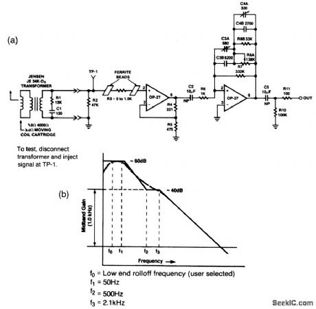
The circuit of Fig. 1-1A is adjusted to match a 40-dB RIAA curve (Fig.1-1B). With break points at 50, 500, and 2100 Hz, the entire curve is fixed by a specified gain at1 kHz. The circuit is designed for use with newer moving-coil magnetic phono cartridges, which have a sensitivity of 0.1 mV per CM/S (compared to older cartridges with sensitivities of1 mV per CM/S). The circuit is adjusted by injecting a low-level signal into TP-1, with the transformer disconnected. At 100 Hz, adjust C3A for an output level that is 6 dB lower than the low-frequency output. At 1000 Hz, adjust R8A for an output level 20 dB lower than the low-frequency output. At 21 kHz, adjust C4A for an output that is 40 dB less than the low-frequency output. Raytheon Linear integrated Circuits 1989, p 4-78, 4-79. (View)
View full Circuit Diagram | Comments | Reading(889)
SQUARE_WAVE_OSCILLATOR
Published:2009/7/22 2:10:00 Author:Jessie
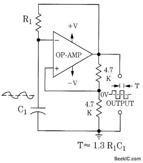
An op amp can be used as a square-wave generator, as shown. (View)
View full Circuit Diagram | Comments | Reading(278)
The Basic Circuit Diagram of 420MHz Intermediate Power Amplifier Composed of RF2104
Published:2011/5/13 4:53:00 Author:May | Keyword: 420MHz, Intermediate Power Amplifier
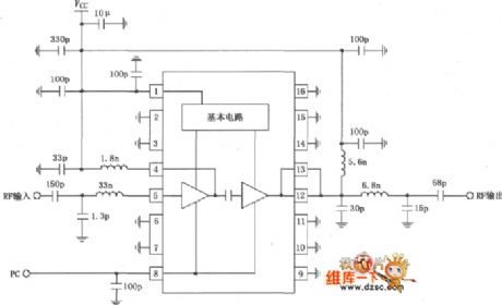
The Basic Circuit Diagram of 420MHz Intermediate Power Amplifier Composed of RF2104 is shown in the following diagram:
(View)
View full Circuit Diagram | Comments | Reading(882)
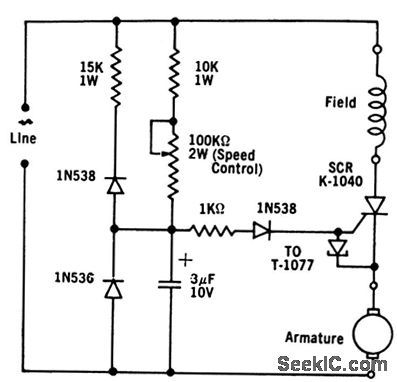
REVERSING_DRIVE_FOR_SERIES_D_C_MOTOR
Published:2009/7/22 2:09:00 Author:Jessie
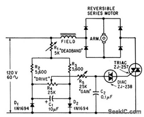
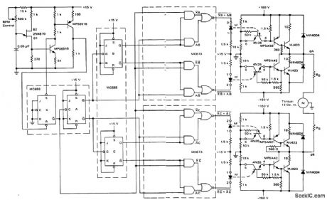
Triode and diode a-c switch Components can be triggered into conducting in either direction by applying positive or negative gate current signal.Transducers can be used in Place of Potentiometer and rheostats to give automatic speed control.-J. C. Hey, The Widening World of the SCR, Electronics,37:25,p 78-85. (View)
View full Circuit Diagram | Comments | Reading(695)
CMOS_INVERTING_SQUARE_WAVE_OSCILLATOR
Published:2009/7/22 2:08:00 Author:Jessie

This CMOS inverting square-wave oscillator can be varied over a wide range. Note that R2 should be 10 times the value of R1, as shown. IC can be a CMOS inverter, or else a NOR or NAND gate wired as an inverter. The frequency is approximately 1/(2.2R1,C1). (View)
View full Circuit Diagram | Comments | Reading(1111)
6_V_D_C_MOTOR
Published:2009/7/22 2:08:00 Author:Jessie
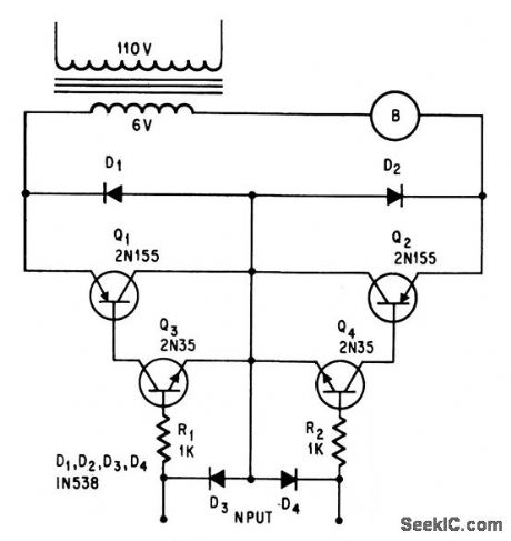
Motor B is energized by rectified voltage from transformer. Direction of rotation is controlled by polarity of input signal, which determines whether Q1 or Q2 is conducting. Motor draws several hundred ma.-J. B. Tiedemann, Transistors Control Small D-c Motor, Electronics, 39:7, p 93 (View)
View full Circuit Diagram | Comments | Reading(632)
MOTOR_NOISE_ACTUATES_MUTING_SYSTEM
Published:2009/7/22 2:07:00 Author:Jessie
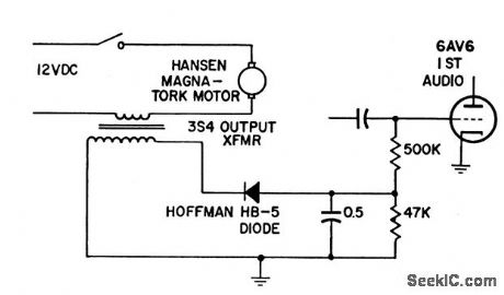
Noise pulses from commutator-type tuning motor in receiver ate rectified and used to bias audio stage to cutoff for as long as tuning motor is running. Audio amplifier re mains cut off for about 0.25 sec after motor stops.-Muting System for Motor-Tuned Receivers, Electronic Circuit Design Handbook, Mactier Pub. Corp, N.Y. 1965, p 51. (View)
View full Circuit Diagram | Comments | Reading(770)
ARBITRARY_DUTY_CYCLE_SQUARE_WAVE_OSCILLATOR
Published:2009/7/22 2:07:00 Author:Jessie
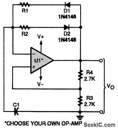
This op-amp-based square-wave generator uses diode switching to produce a fixed duty cycle other than 50 percent. (View)
View full Circuit Diagram | Comments | Reading(1819)
SPEED_FEEDBACK
Published:2009/7/22 2:07:00 Author:Jessie
Introduction of speed feed-back signal into firing circuit helps maintain constant torque regardless of speed. Tunnel diodes provide excellent stabilizing action at tow speeds.-TD/SDR Combos for Sale, EEE, 12:3, p 62-64. (View)
View full Circuit Diagram | Comments | Reading(886)
FIELD_EFFECT_TRANSISTOR_CONTROLS_PULSE_OSCILLATOR
Published:2009/7/22 2:05:00 Author:Jessie
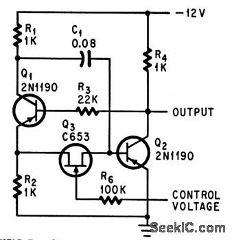
C653 transistor serves as voltage-controlled nonlinear resistor that varies time constant of oscillator. Can generate narrow output pulses at rates up to several Mc, to drive stepping motor.-T. C. Ross, Field-effect transistor Controls Pulse Oscillator, Electronics, 37:18, p 80-81. (View)
View full Circuit Diagram | Comments | Reading(734)
THREE_SPEED_BLENDER_CONTROL
Published:2009/7/22 2:05:00 Author:Jessie
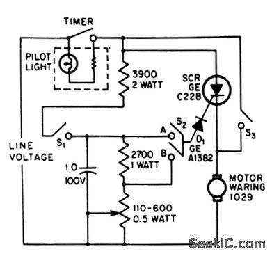
Single scr safely handles 7.5-amp current of 1/2-hp motor. Feedback is used to change firing angle of scr as load increases, to maintain constant blending speed.-J. Eimbinder, SCRs In The Consumer Market, FEE, 14:8, p 100-103. (View)
View full Circuit Diagram | Comments | Reading(1929)
STEPPER_MOTOR__PULSE__GENERATOR
Published:2009/7/22 2:03:00 Author:Jessie
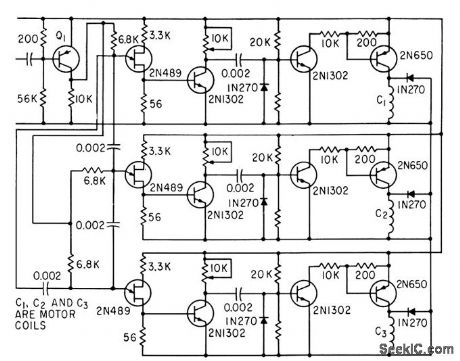
Unijunction ring counter energizes winding of stepper motor sequentially,-F.W. Kear, Digital Control Uses Unijunction Transistors, Electronics, 34:18, p 79-80. (View)
View full Circuit Diagram | Comments | Reading(835)
SQUARE_WAVE_OSCILLATOR_1
Published:2009/7/22 3:13:00 Author:Jessie
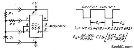
This circuit will produce a 50-percent duty cycle from a 555. (View)
View full Circuit Diagram | Comments | Reading(623)
Remote_control_of_ac_voltage
Published:2009/7/22 3:12:00 Author:Jessie
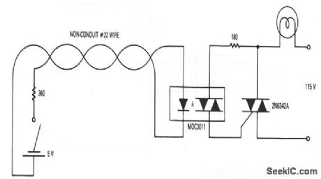
This circuit shows an MOC3011 optoisolator used for remote control of ac voltages. Local building codes frequently require that all 115-V light-switch wiring be enclosed in conduit. With this circuit, it is possible to control a large lighting load from a long distance through low-voltage (5 V) signal wiring, which is completely isolated from the ac line. Such wiring usually is not required to be in conduit, so the cost savings (especially in large commercial or residential build-ings) can be considerable. Although a lighting load is shown, the load can be a motor, fan, pool pump, etc. (View)
View full Circuit Diagram | Comments | Reading(1665)
SCHMITT_TRIGGER_RC_OSCILLATOR
Published:2009/7/22 2:26:00 Author:Jessie
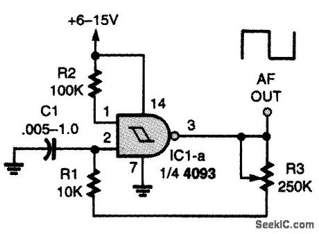
Here's another square-wave oscillator that uses a CMOS IC with input hysteresis. In this RC oscillator circuit, a single gate of a quad two-input NAND Schmitt-Trigger IC is the active element. (View)
View full Circuit Diagram | Comments | Reading(3310)
Nonzero_crossing_optically_isolated_triac_drivers
Published:2009/7/22 2:25:00 Author:Jessie
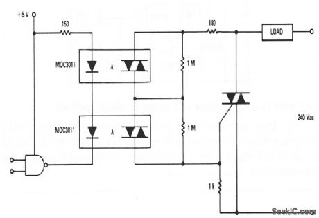
This circuit shows two MOC3011 optoisolators used to drive a 240-V triac-controlled load-even though the individual MOC3011 voltage rating is not sufficiently high to be used directly on a 240-V line. The two 1-MΩ resistors equalize the voltage on the MOC3011s. (View)
View full Circuit Diagram | Comments | Reading(716)
High_speed_FIFO_memory_using_the_MC10143_register_file
Published:2009/7/22 2:24:00 Author:Jessie
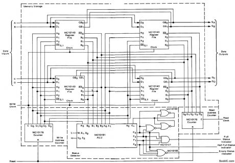
High-speed FIFO memory using the MC10143 register file (courtesy Motorola Semiconductor Products Inc.). (View)
View full Circuit Diagram | Comments | Reading(876)
Full_wave_thyristor_control_with_average_voltage_feedback
Published:2009/7/22 2:23:00 Author:Jessie
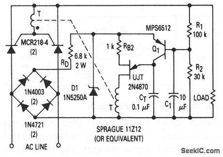
This circuit shows a UJT that is used as a thyristor rigger (with feedback), where the average full-wave load voltage is the desired feedback variable. Notice that the line voltage is first rectified. R1, R2, and C1 average the load voltage so that the voltage can be compared with the rectified line voltage. (View)
View full Circuit Diagram | Comments | Reading(750)
RIAA_preamplifier
Published:2009/7/22 2:23:00 Author:Jessie
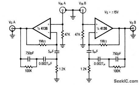
This circuit also uses only one half of the 4136 (Fig.1-4). (View)
View full Circuit Diagram | Comments | Reading(0)
Stereo_tone_control
Published:2009/7/22 2:22:00 Author:Jessie
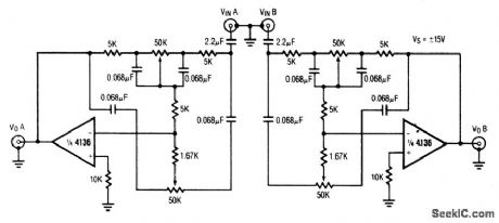
This circuit uses only one-half of the 4136(Fig.l-5) (View)
View full Circuit Diagram | Comments | Reading(0)
| Pages:1021/2234 At 2010211022102310241025102610271028102910301031103210331034103510361037103810391040Under 20 |
Circuit Categories
power supply circuit
Amplifier Circuit
Basic Circuit
LED and Light Circuit
Sensor Circuit
Signal Processing
Electrical Equipment Circuit
Control Circuit
Remote Control Circuit
A/D-D/A Converter Circuit
Audio Circuit
Measuring and Test Circuit
Communication Circuit
Computer-Related Circuit
555 Circuit
Automotive Circuit
Repairing Circuit