
Circuit Diagram
Index 1340
NATIONAL_SEMICONDUCTOR
Published:2009/6/24 4:05:00 Author:May
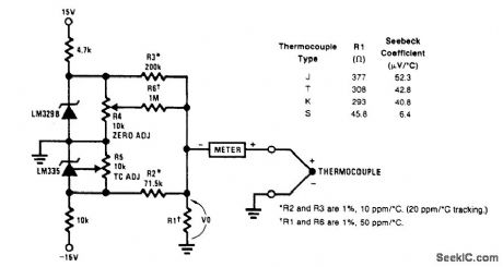
A circuit for use with grounded thermocouples is shown. To trim, short out the LM329B and ad-just R5 so that V°= αT, where cc is the Seebeck coefficient of the thermocouple and T is the absolute temperature. Remove the short and adjust R4 so that W equals the thermocouple output voltage at ambient. A good grounding system is essential here, for any ground differential will appear in series with the thermocouple output. (View)
View full Circuit Diagram | Comments | Reading(0)
DIFFERENTIAL_THERMOMETER
Published:2009/6/24 4:18:00 Author:Jessie
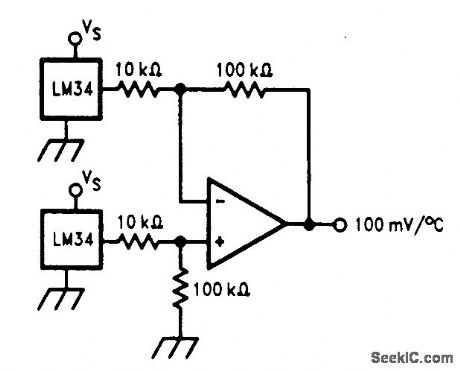
The differential thermometer shown in the figure produces an output voltage which is proportional to the temperature difference between two sensors. This is accomplished by using a dif-ference amplifier to subtract the sensor outputs from one another and then multiplying the differ-ence by a factor of 10 to provide a single-ended output of 100 mV per degree of differential tem-perature. (View)
View full Circuit Diagram | Comments | Reading(1)
UNIVERSAL_WIPER_DELAY
Published:2009/6/24 4:04:00 Author:May
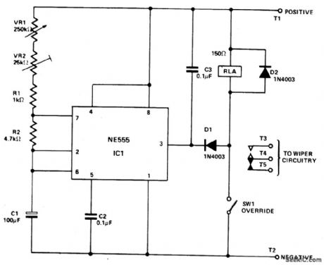
IC1 is connected in the astable mode, driving RLA. C3, Dl, and D2 prevent spikes from the relay coil and the wiper motor from triggering IC1. VR2 is adjusted to give the minimum delay time required. VR1 is the main delay control and provides a range of from about 1 second to 20 seconds. SW1 is an over-ride switch to hold RLA permanently on (for normal wiper operation). The relay should have a resistance of at least 150 ohms and have heavy duty contacts. The suppression circuit may be needed for the protection of IC1. (View)
View full Circuit Diagram | Comments | Reading(0)
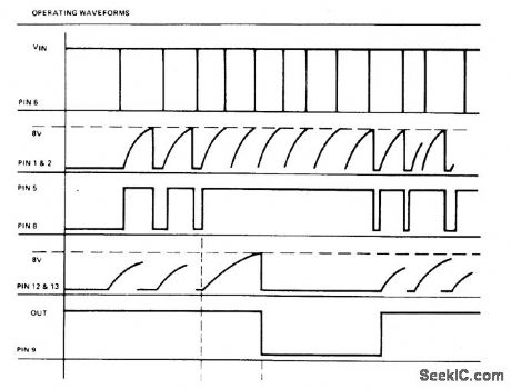
OPERATING_WAVEFORMS
Published:2009/6/24 4:03:00 Author:May
View full Circuit Diagram | Comments | Reading(0)
TEMPERATURE_TO_FREQUENCY_CONVERTER_KELVIN
Published:2009/6/24 4:17:00 Author:Jessie
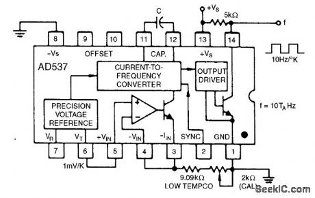
This simple connection results in a direct conversion of temperature to frequency. The 1-mV/°K temperature output serves as the input to the buffer amplifier, and the oscillator drive current is scaled to be 298μA at 298°K (+25℃). Use of a 1000-pF capacitor results in a corresponding fre-quency of 2.98 kHz. A single-point trim for calibration is normally sufficient to give errors less than ±2℃ from -55℃ to +125℃. An NPO capacitor is preferred to minimize nonlinearity that results from capacitance drift. (View)
View full Circuit Diagram | Comments | Reading(0)
EIGHT_INPUT_A_D_CONVERTER_FOR_TEMPERATURE_MEASUREMENTS
Published:2009/6/24 4:03:00 Author:May
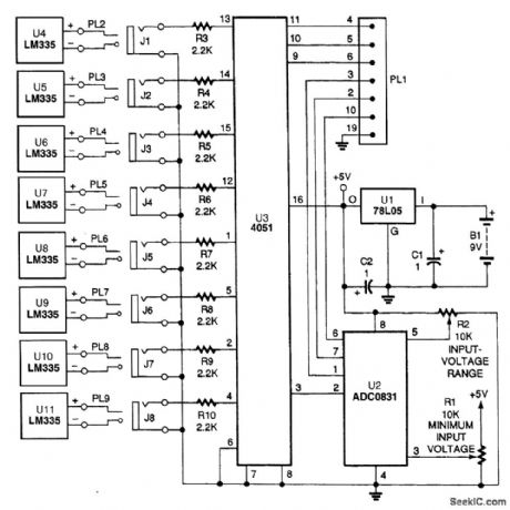

The actual processing circuitry of this A/D converter consists of only four parts: U2, U3, R1 and R2. Eight temperature probes are used with the circuit; however, they can be replaced with other types of sensors, as long as resistors R3 through R10 are removed.
(View)
View full Circuit Diagram | Comments | Reading(0)
SPEED_WARNING_DEVICE
Published:2009/6/24 4:03:00 Author:May
View full Circuit Diagram | Comments | Reading(1422)
TEMPERATURE_TO_FREQUENCY_CONVERTER_CELSIUS
Published:2009/6/24 4:17:00 Author:Jessie
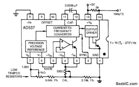
The 1.00-V reference output can be combined with the 1-mV/°K output to realize various temperature scales. For the Celsius scale, the lower end of the timing resistor must be offset by 273 mV. This is easily accomplished, and it results in an output from 0 to 1 kHz for temperatures from 0℃ to +100℃. Other offsets and scale factors are equally easy to implement. (View)
View full Circuit Diagram | Comments | Reading(1824)
AF_POWER_OSCILLATOR
Published:2009/6/24 4:15:00 Author:Jessie
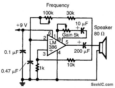
An LM386 audio power IC is set up as a feedback oscillator. Any supply from 6 to 12 V can be used. The circuit can drive a loudspeaker. (View)
View full Circuit Diagram | Comments | Reading(1471)
PROPORTIONAL_TEMPERATURE_CONTROLLER
Published:2009/6/24 4:01:00 Author:May


Most temperature-controller circuits use upper and lower trip points to control a heater element, with the heater power full on and full off. Usually, this results in a temperature hysteresis of several degrees. This relatively large temperature hysteresis effect might cause modulation in the output of the circuit that's being controlled.
A proportional temperature controller eliminates this problem by continuously providing the power needed to maintain the oven at the desired temperature-within 1℃. From a cold start, maximum power is applied until the temperature is within 2℃ of the set point.
The circuit's mechanical construction is important. The five heater resistors (R12 through R16), the temperature-sensor IC (U1), and the circuit being controlled are mounted with thermal epoxy to a small piece of aluminum. This provides excellent heat transfer between the components. The heater resistors must be selected to raise the temperature from ambient to the set point within an acceptable warm-up time.
U1 is Analog Devices' TMP-01 temperature- controller IC. The voltage proportional to absolute temperature (VPTAT) has a temperature coefficient of exactly 5 mV/℃. The set point is determined by the R1/R2 ratio. U2 is a Linear Technology LT1014 quad precision op amp. U2C is an oscillator with a 50% duty cycle that supplies a triangle wave between 1/3 and 2/3 of the supply voltage at U2-2
U2B compares the amplified VPTAT to the triangle wave, which drives Q1 at a duty cycle of 100% or less. Because the triangle wave's peak-to-peak amplitude is 2.7 V, and VPTAT is amplified by a factor of 300, a temperature change of approximately 2 mV moves the duty cycle from 100% to 0%. (View)
View full Circuit Diagram | Comments | Reading(0)
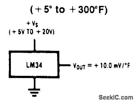
BASIC_FAHRENHEIT_TEMPERATURE_SENSOR
Published:2009/6/24 4:14:00 Author:Jessie
View full Circuit Diagram | Comments | Reading(2393)
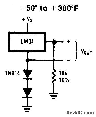
SINGLE_SUPPLY_TEMPERATURE_SENSOR(_50_TO__300°F)
Published:2009/6/24 4:14:00 Author:Jessie
View full Circuit Diagram | Comments | Reading(1685)
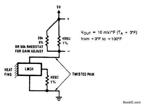
TWO_WIER_REMOTE_TEMPERATURE_SENSOR_WITH_SENSOR_GROUNDED
Published:2009/6/24 4:13:00 Author:Jessie
View full Circuit Diagram | Comments | Reading(731)
SPEED_ALARM
Published:2009/6/24 4:00:00 Author:May
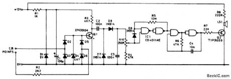
Pulses from the distributor points are pas-sed through a current limiting resistor, rec-tified, and clipped at 4.7 volts. Via Q1 and the diode pump, a dc voltage proportional to engine rpm is presented to RV1; the sharp transfer characteristic of a CM0S gate, assisted by feedback, is used to enable the oscillator formed by the remaining half of the 4011. At the pre-set speed, a nonignorable tone emits from the speaker, and disappears as soon as the speed drops by three or four mph. (View)
View full Circuit Diagram | Comments | Reading(1016)
VARIABLE_SENSITIVITY_PHOTOTRANSISTOR_CIRCUIT
Published:2009/6/24 4:00:00 Author:May
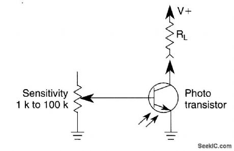
A variable resistor is used to vary the light-level response of a phototransistor. Phototransistors are more light sensitive than photodiodes, but they generally have poorer frequency response. (View)
View full Circuit Diagram | Comments | Reading(3133)
GASOLINE_ENGINE_TACHOMETER
Published:2009/6/24 3:59:00 Author:May
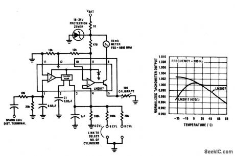
This tachometer can be set up for any number of cylinders by linking the appropriate timing resistor as illustrated. A 500 ohm trim resistor can be used to set up final calibration.A protection circuit composed of a 10 ohm resistor and a zener diode is also shown as a safety precaution against the transients which are to be found in automobiles. (View)
View full Circuit Diagram | Comments | Reading(816)
TAPE_PLAUBACK_AMPLIFIER
Published:2009/6/24 3:57:00 Author:May
View full Circuit Diagram | Comments | Reading(693)
TACHOMETER
Published:2009/6/24 4:10:00 Author:Jessie
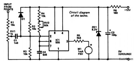
An electrical signal taken from the low tension side of the distributor is converted into a voltage proportional to engine rpm and this voltage is displayed on a meter calibrated ac-cordingly. The 555 timer IC is used as a monostable which, in effect, converts the sig-nal pulse from the breaker points to a single positive pulse the width of which is determined by the value of R4 + RV2 and C2. Resistors R2 and R3 set a voltage of about 4 volts at pin 2 of IC1. The IC is triggered if this voltage is re-duced to less than approximately 2.7 volts (1/3 of supply voltage), and this occurs due to the voltage swing when the breaker points open.An adjustment potentiometer RV1 enables the input level to be set to avoid false triggering. Zener diode ZD1 and the 180 ohm resistor stabilize the unit against voltage variations. (View)
View full Circuit Diagram | Comments | Reading(4)
BARGRAPH_CAR_VOLTMETER
Published:2009/6/24 4:08:00 Author:Jessie
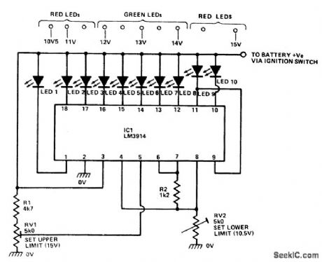
The LM3914 acts as a LED-driving vol-tometer that has its basic maximum and minimum readings determined by the values of R2 and RV2. When correctly adjusted, the unit actually covers the 2.5 volt to 3.6 volt range, but it is made to read a supply voltage span of 10-10.5 volts to 15 volts by interposing poten-tial divider R1-RV1 between the supply line and the pin-5 input terminal of the IC. The IC is configured to give a 'dot' display, in which only one of the ten LEDs is illuminated at any given time. If the supply voltage is below 10.5 volts none of the LEDs illuminate. Ifthe supply equals or exceeds 15 volts, LED 10 illuminates. (View)
View full Circuit Diagram | Comments | Reading(0)
ABSOLUTE_TEMPERATURE_LOG_WITH_RS_232
Published:2009/6/24 4:08:00 Author:Jessie
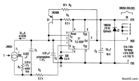
In the setup, T1 (an LM334 temperature sensor) generates a constant current that's propor-tional to absolute temperature, and equal to 25μA at 323 Kelvin (50℃). RI sets this constant of pro-portionality. The current discharges the parallel combination of C1 and C2 connected to the trigger and the threshold pins of UI, which is a CMOS implementation of the venerable 555 analog timer.The negative-going ramp is compared by UI to an internal2.S-V trigger level controlled by 21. When the ramp gets there, U1 triggers. The output pin (3) will go high, presenting a start bit to the con-nected communications port, which causes Q1 to source 100 μA to the timing node. At the same time, the discharge pin (7) will open, allowing R2 and the bottom end of C1 and T1 to be supplied by C1, and isolates it from C2.
Consequently, the current supplied by transistor Q1 will go solely to C2 so that when the result-ing positive-going ramp reaches 5V, exactly 25nC (2.5 V x C2) will have been deposited in the tim-ing node by the recharge cycle because its threshold level (6) will have been reached. This causes both the output pin to return to the negative rail, restoring the marking condition of the R2-232 in-terface, and Q1 to stop recharging C2. U1's discharge pin (7) now connects R2 to the negative rail, causing the charge that was deposited by T1 on C1 during the recharge interval to rapidly redistrib-ute between C1 and C2. This arrangement creates a very linear (0.01%) relationship between T1 cur-rent and pulse output frequency.
While this is happening, the PC's communications port hardware assembles a valid (although meaningless) character because the positive pulse output by UI looks like the start bit of a charac-ter. A simple program running in the PC can then count the frequency of these characters and con-vert the resulting rate into a direct readout of temperature. Because of the 3.1-Hz/degree slope of frequency versus temperature, a 30-second average suffices for 0.01°resolution. (View)
View full Circuit Diagram | Comments | Reading(2324)
| Pages:1340/2234 At 2013211322132313241325132613271328132913301331133213331334133513361337133813391340Under 20 |
Circuit Categories
power supply circuit
Amplifier Circuit
Basic Circuit
LED and Light Circuit
Sensor Circuit
Signal Processing
Electrical Equipment Circuit
Control Circuit
Remote Control Circuit
A/D-D/A Converter Circuit
Audio Circuit
Measuring and Test Circuit
Communication Circuit
Computer-Related Circuit
555 Circuit
Automotive Circuit
Repairing Circuit