
Circuit Diagram
Index 1620
elaborately improved fan speed control circuit
Published:2011/7/5 10:17:00 Author:John | Keyword: fan
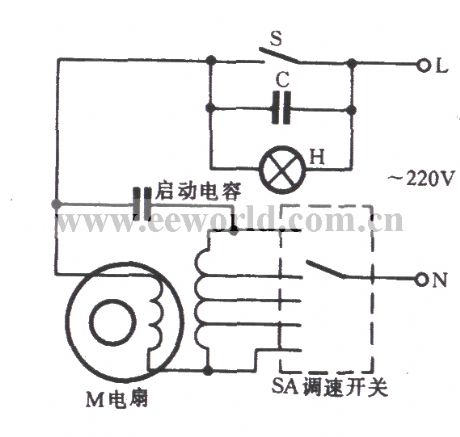
As shown in the circuit, capacitor C is generally used in 2.5 ~ 4.7μF/400V. Both ends of the C are connected with a switch S in parallel. When the S is closed, C is short and the fan operates according to the governor SA’s original gear operation. When S is turned off, the C is applied into the circuit in series. Due to its capacitance, the speed of fan motor M is reduced although governor SA’s gear operation is not changed. However, the wind speed is lower than the original one. H is a light of 8 ~ 10W. It can work as a light in a weak windshield, as well as providing a discharge path for capacitor C when the city power is cut.
(View)
View full Circuit Diagram | Comments | Reading(790)
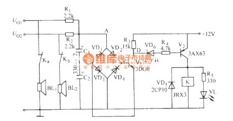
bridge and pick-up type speaker protection circuit (b)
Published:2011/7/5 10:07:00 Author:John | Keyword: speaker
View full Circuit Diagram | Comments | Reading(2425)
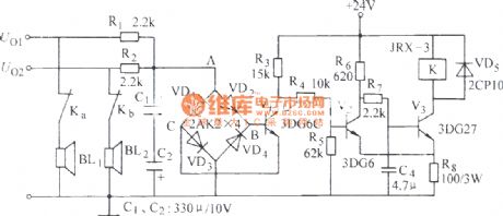
bridge and pick-up type speaker protection circuit c
Published:2011/7/5 10:07:00 Author:John | Keyword: speaker
View full Circuit Diagram | Comments | Reading(2110)
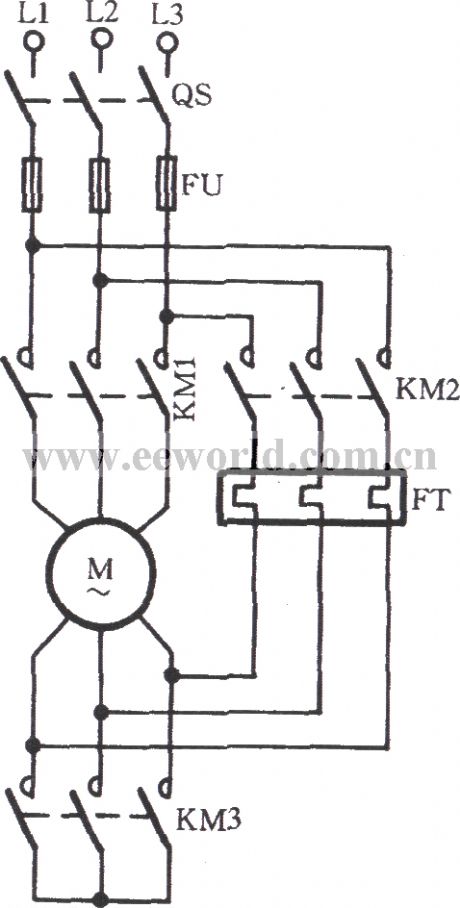
Y-△ main circuit during the starting of thermal relay in Y
Published:2011/7/5 4:06:00 Author:John | Keyword: thermal relay
View full Circuit Diagram | Comments | Reading(729)
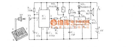
Gas stove safety valve control and language alarming circuit
Published:2011/7/5 3:56:00 Author:John | Keyword: Gas stove, safety valve
PDF for related components can be downloaded.
5559013SR8808The circuit is as shown. It consists of the gas sensor, one-shot trigger circuit, relay control motor circuits, voice circuit and communication buck rectifier circuit. When the gas concentration detected by the gas sensor exceeds a given concentration, the exhaust fan is automatically turned on and is issued whistles, thus being able to attract people’s attention and vigilance.
(View)
View full Circuit Diagram | Comments | Reading(1207)
1.5V power supply making circuit
Published:2011/7/5 19:42:00 Author:Christina | Keyword: 1.5V, power supply, making circuit
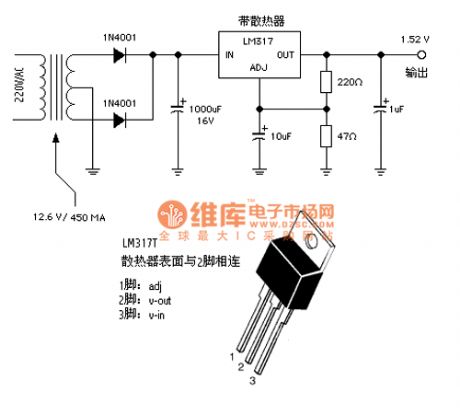
Some portable electronic devices such as the walkman and the MD often use the 1.5 V power supply. Some times you need to use the 1.5V power supply to replace battery. Here I introduce the 1.5V power supply circuit which is composed of the LM317T. This circuit is simple and has good performance, if you connect it according to the figure, you need not to debug it.
(View)
View full Circuit Diagram | Comments | Reading(3027)
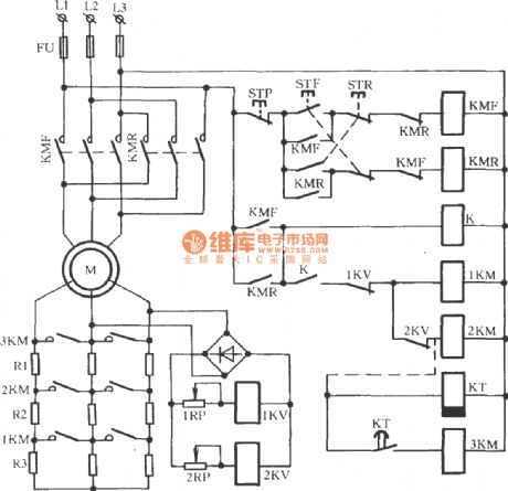
Wound rotor type motor reverse brake circuit
Published:2011/7/5 3:51:00 Author:John | Keyword: Wound rotor, motor
View full Circuit Diagram | Comments | Reading(1755)
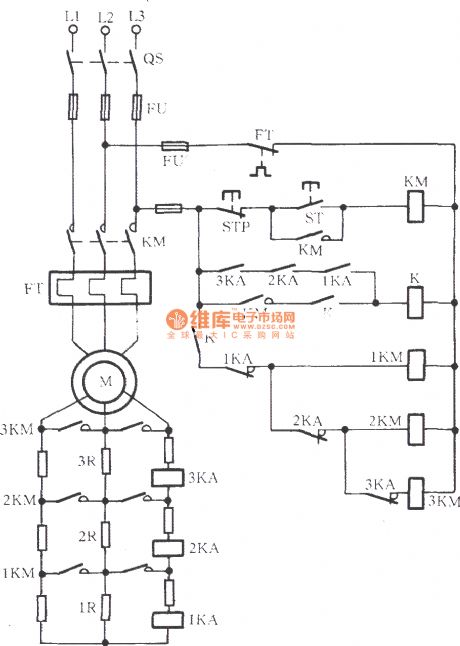
Wound rotor induction motor manual and automatic serial reactor step-down start-up circuit
Published:2011/7/5 3:50:00 Author:John | Keyword: serial reactor, Wound rotor, induction motor
View full Circuit Diagram | Comments | Reading(3077)
Wound rotor induction motor ultilizing current variation starting circuit
Published:2011/7/5 3:49:00 Author:John | Keyword: Wound rotor, induction motor
View full Circuit Diagram | Comments | Reading(1777)
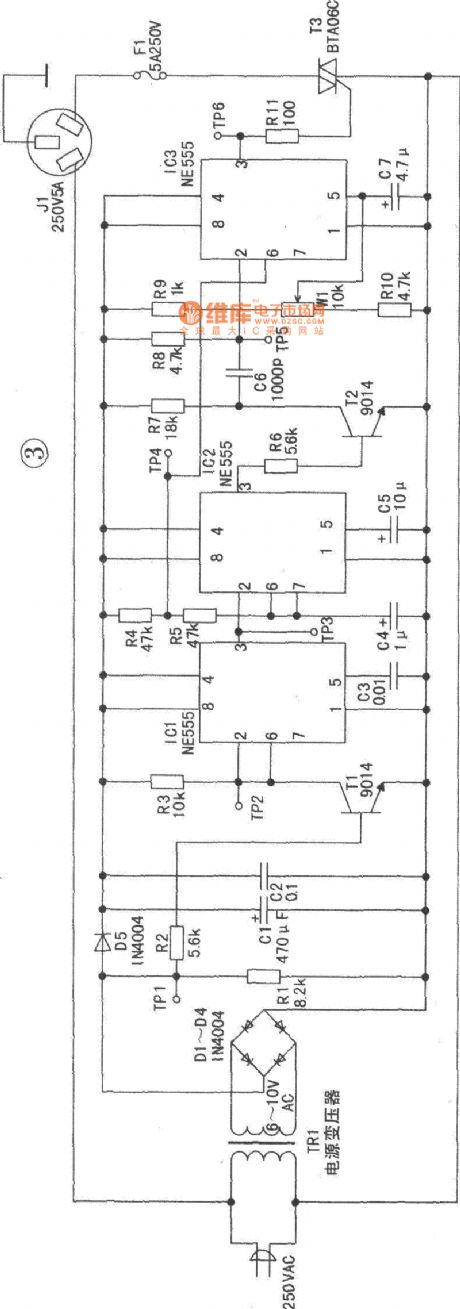
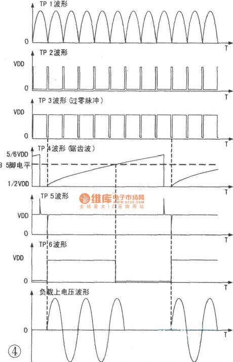
Silicon controlled zero-crossing trigger voltage regulator circuit
Published:2011/7/5 19:48:00 Author:Christina | Keyword: Silicon controlled, zero-crossing, trigger, voltage regulator
View full Circuit Diagram | Comments | Reading(1139)
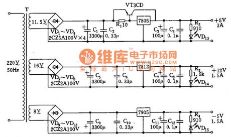
+12V, ±5V output power supply circuit
Published:2011/7/5 19:59:00 Author:Christina | Keyword: +12V, ±5V, output, power supply
View full Circuit Diagram | Comments | Reading(845)
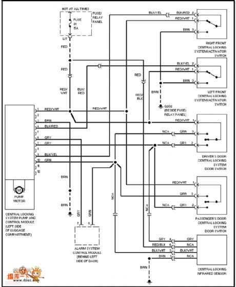
Volkswagen electric door lock circuit
Published:2011/7/5 20:01:00 Author:Christina | Keyword: Volkswagen, electric door, lock circuit
View full Circuit Diagram | Comments | Reading(870)
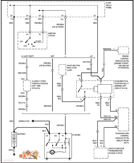
Volkswagen start-up circuit
Published:2011/7/5 20:01:00 Author:Christina | Keyword: Volkswagen, start-up circuit
View full Circuit Diagram | Comments | Reading(507)
wound rotor induction motor serial reactor step-down starting circuit
Published:2011/7/4 23:49:00 Author:John | Keyword: wound rotor, induction motor, reactor
View full Circuit Diagram | Comments | Reading(2436)
Thermal relay overload protection circuit
Published:2011/7/5 4:04:00 Author:John | Keyword: Thermal relay
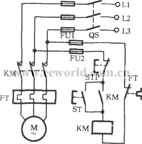
Thermal relay overload protection circuit can be applied to avoid the failure, which is as shown. FT is the thermal relay in the string for the circuit. When motor M is overloaded, internal heating elements of FT are heated. Then the bimetal pieces bend to promote the FT’s normally closed contacts to disconnect. Thus, the AC power contactor KM coil is off. The main contact KM is off to stop the motor M. at the end, the overload failure of the winding burn can be effectively eliminated. After the overload failure being removed, Reset button of the thermal relay is pressed as well as the starting button ST. Finally, the motor can start again.
(View)
View full Circuit Diagram | Comments | Reading(6179)
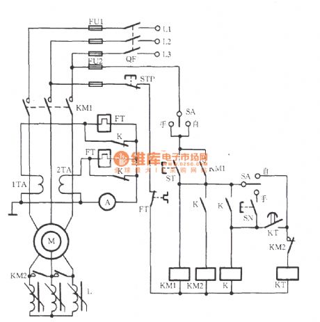
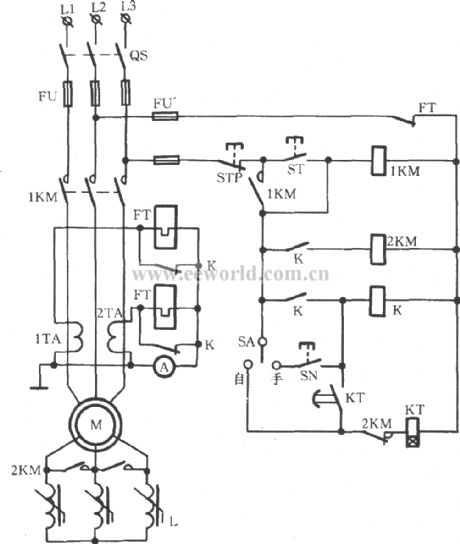
Vertical mill electrical control circuit
Published:2011/7/5 0:03:00 Author:John | Keyword: Vertical mill
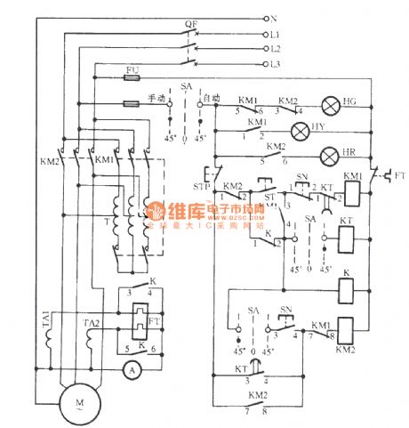
The button ST is pressed to induct the KM1 coil circuit. When the pin 5-6 of KM1 is disconnected, HG is off; and when the pin 1~2 is connected, yellow light HY lights. This indicated that it is starting. The pin 7-8 of KM1 is disconnected to prevent KM2 from being powered under accidental circumstances. Thus, the interlock between KM1 and KM2 has been achieved. When the contact 3-4 of KM1 is closed, KM1 is self-locked. This is able to lead the timing relay KT to start to work. (SA’s contacts are connected), but also to close the middle relay K by electric pull. Then the contact 3 ~ 4 and contact 5 ~ 6 both close. As a result, the heating element in the hot relay circuit is in short, thus preventing motor M from FT’s malfunction while staring with high current.
(View)
View full Circuit Diagram | Comments | Reading(4107)
freezer and cooling pump interlock control circuit
Published:2011/7/5 0:07:00 Author:John | Keyword: freezer, cooling pump, interlock
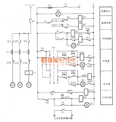
The freezer and cooling pump interlock control circuit is as shown. It can be started through starting frozen pump, cooling pump and opening the freezer boot process. It can be stopped by the reverse process
(View)
View full Circuit Diagram | Comments | Reading(2295)
Delicate automatic rice cooker 2
Published:2011/7/5 0:38:00 Author:John | Keyword: rice cooker
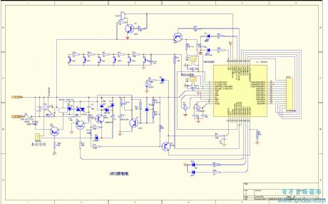
PDF for related components can be downloaded.
BT13480508550S3P2289015
(View)
View full Circuit Diagram | Comments | Reading(1560)
Delicate automatic rice cooker 1
Published:2011/7/5 0:40:00 Author:John | Keyword: automatic rice cooker
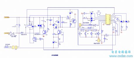
PDF for related components can be downloaded.
BT13480508550HT46R47 (View)
View full Circuit Diagram | Comments | Reading(3004)
Electrocardiogram (ECG) Amplifying Circuit
Published:2011/7/1 2:41:00 Author:Joyce | Keyword: Electrocardiogram , (ECG) , Amplifying
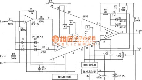
Cardiovascular disease has become a very common disease, and with the speeding pace of life and people’s increasing awareness of life standard and health, they need to exam and protect their hearts at any time and to carry out timely treatment in emergency. As shown in the electrocardiogram (ECG) amplifying circuit, it does not only use transformer coupling isolated amplifier 3656 , but also uses a piece of precision operation amplifier OPA177 (offset voltage≤ 10μV ,the offset voltage drift is 0.1 μV / ℃,the open-loop gain is greater than 130 dB, and the static typical current is 1.5 mA). (View)
View full Circuit Diagram | Comments | Reading(1696)
| Pages:1620/2234 At 2016011602160316041605160616071608160916101611161216131614161516161617161816191620Under 20 |
Circuit Categories
power supply circuit
Amplifier Circuit
Basic Circuit
LED and Light Circuit
Sensor Circuit
Signal Processing
Electrical Equipment Circuit
Control Circuit
Remote Control Circuit
A/D-D/A Converter Circuit
Audio Circuit
Measuring and Test Circuit
Communication Circuit
Computer-Related Circuit
555 Circuit
Automotive Circuit
Repairing Circuit