
Circuit Diagram
Index 1601
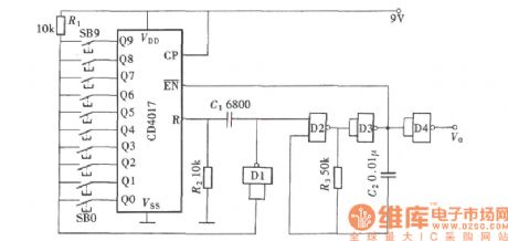
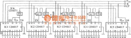
Diagram of 1 to 9 Pulse Selection Circuit
Published:2011/6/15 8:11:00 Author:Vicky | Keyword: Diagram of 1 to 9 Pulse Selection Circuit,
(View)
View full Circuit Diagram | Comments | Reading(736)
Typical Applied Circuit Diagram of LM4610 Integrated Circuit
Published:2011/6/15 8:09:00 Author:Vicky | Keyword: Typical Applied Circuit Diagram
Typical Applied Circuit
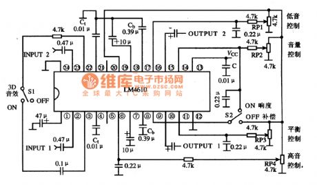
Typical applied circuit diagram of LM4610 integrated circuit is shown in the following picture. The LM4610 circuit uses 4 potentiometers MU-M as bass control, volume control, treble control and balance control respectively.
Hint: Left/Right acoustical signal enter LM4610 from (2) pin and (23) pin, get out from (10) pin and (15) pin after processed by the sound volume, tone, balance and 3D audio, and then go to the post-stage circuit. It can be justified that whether LM4610 works regularly by this four pins.
(View)
View full Circuit Diagram | Comments | Reading(3213)
Typical Applied Circuit Diagram of LM8363D/DH Integrated Circuit
Published:2011/6/15 8:07:00 Author:Vicky | Keyword: Typical Applied Circuit Diagram of LM8363D/DH Integrated Circuit,
Picture: Typical Applied Circuit of LM8363D/DH integrated circuit
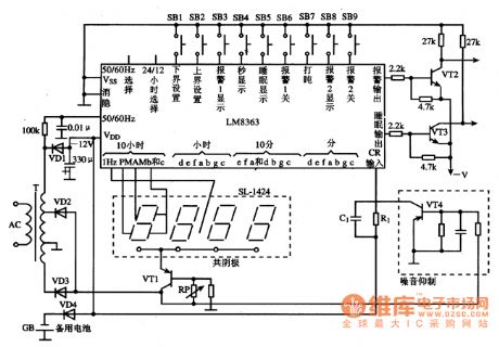
Typical applied circuitTypical applied circuit diagram of digital circuit ,which is composed of LM8363D/DH integrated circuit, is as shownin the picture.
Hint: LM8363 integrated circuit can be thereserve when the power is cut off, and selection method of the value reuired by the osillator is listed below:
grade of 60Hz:R1=130k、C1=0.0068μF,f。=1.92kHz;
grade of 50Hz:R1=150k、C1=0·0068μF,f。=1.6kHz. (View)
View full Circuit Diagram | Comments | Reading(2628)
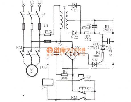
the circuit of loss-of-phase protecting relay for electric motor (4)
Published:2011/6/16 8:29:00 Author:Ariel Wang | Keyword: loss-of-phase , protecting, relay, electric, motor
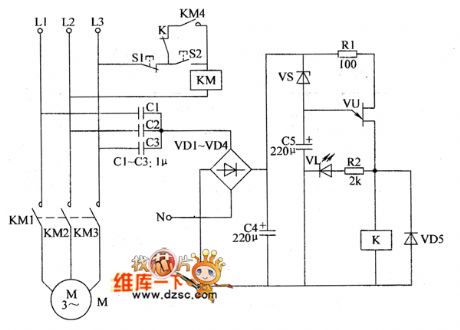
When there is one phase missing in three-phase power supply ,it will generate around 12V AC voltage between A point and zero line N rapidly.It is commutated by VD1-VD4 and filtered by C4.VS is conducted.C5 begins to charge.After a few minutes(after C5 finishes charging),VU is conducted.VL is lighted.K pulls in.normally-closed contact is disconnected.Then AC contactor is released.The working power supply of electric motor M is cut down .When three-phase power supply is normal,K is released.Then you can press start push button to restart the electric motor. (View)
View full Circuit Diagram | Comments | Reading(1256)
Arbitrary Number System Output Circuit Diagram
Published:2011/6/15 8:22:00 Author:Vicky | Keyword: Arbitrary Number System
Output Circuit of arbitrary number system (View)
View full Circuit Diagram | Comments | Reading(719)
Arbitrary Number System Counter Output Circuit Diagram
Published:2011/6/15 8:22:00 Author:Vicky | Keyword: Arbitrary Number System Counter ,
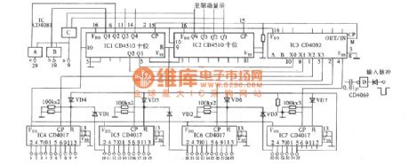
Output Circuit Diagram of Arbitrary Number System Counter (View)
View full Circuit Diagram | Comments | Reading(933)
Self Quality Detector Circuit Diagram
Published:2011/6/15 8:00:00 Author:Vicky | Keyword: Self Quality Detector
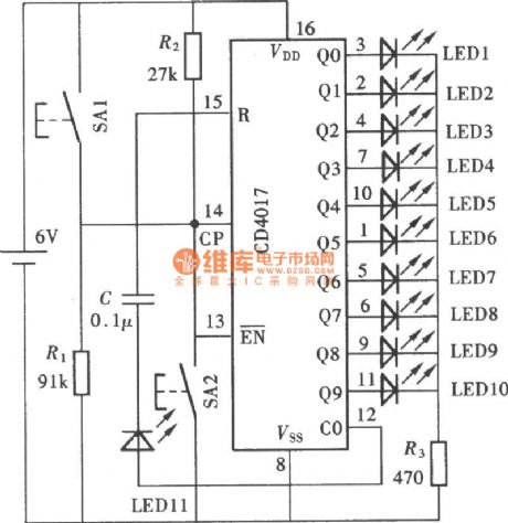
CD4017 is one of the most commonly used digital integrated circuits among all kinds of practical electronic circuits. The following is a simple Quality Detector and it can test the following details: first, whether the output performance of the ten output ends, Q0~Q9, is good or not; second, whether the input performance of clock pulse input end is good; third, whether the reset function of the reset terminal R works well; forth, whether the carry pulse output of the carry pulse output end CO works well. (View)
View full Circuit Diagram | Comments | Reading(917)
the alarm for overlimt of temperature and humidity
Published:2011/6/20 7:43:00 Author:Ariel Wang | Keyword: alarm, overlimt, temperature, humidity

When the humidity of soil in shed is beyond the upper limit of the set temperature,the resistence between the electrode a and b decreases.The neutral point potential of RP2 is lower than 2.7V.D2 outputs high level.D3 outputs low level.VL2 is lighted.It indicates the amount of humidity in shed is too much.At the same time,V is conducted.IC2 is conducted to work.B1 gives out alarm sound.When the humidity of soil in shed is lower than the lower limit of the set humidity.The resistence between electrode a and b increases.The neutral point potential of RP1 is higher than 2.7V.D1 outputs low level.VL1 is lighted.It indicates the amount of humidity in shed is not enough.At the same time V is conducted.IC2 is conducted to work.BL gives out alarm sound. (View)
View full Circuit Diagram | Comments | Reading(445)
The thyristor broken phase protection circuit
Published:2011/7/6 0:55:00 Author:Borg | Keyword: thyristor, broken phase, protection
View full Circuit Diagram | Comments | Reading(753)
The Communication Single Door PC Intergrated Circuit of C807-1354
Published:2011/6/14 23:23:00 Author:Borg | Keyword: Intergrated Circuit, Communication, Single Door
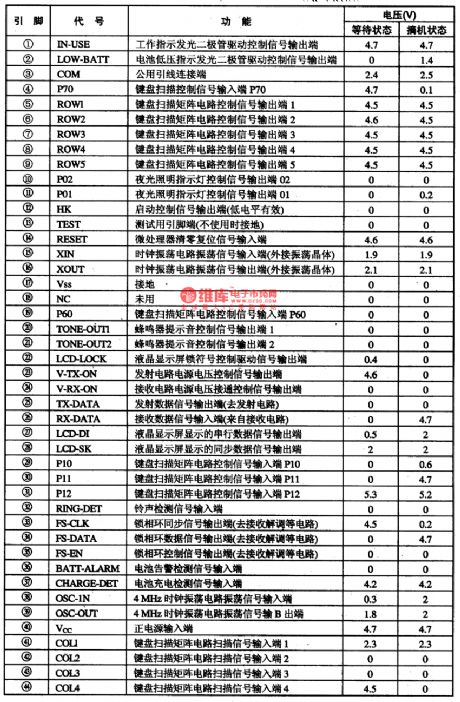
C807一1354 is an PC intergrated circuit of communication single door which is used in wirless phones as the bus master of cell phones.
1.function features
C807一1354 intergrated circuits contain control circuits of wireless delivering/receiving,LCD drive, lighting lamps, key switch encoding/decoding, clock shocking, in it, phase-locked loop signal handling, buzzer drive, code generating and conditioning, low voltage test,charging and othe functions.
2.pin functions and relevent data
C807—1354 intergrated circuits areencapsulated with 44-lead,whose pin functions and data are listed in Table 1.
Table 1 pin functions and data of C807-1354 (View)
View full Circuit Diagram | Comments | Reading(747)
The auto-control ventilator circuit of 555
Published:2011/6/14 23:27:00 Author:Borg | Keyword: auto-control circuit
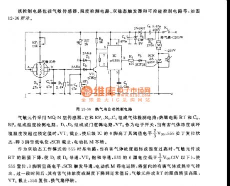
Figure 12-36 The auto-control circuit of ventilators The gas-sensitive element is fixed with MQ-N sensor, whichforms the gas detection circuit with RP1,R1 and C1; the thermistor of RT, C2 and RP3 form the temperature detection circuit. D1 and D2 form the logic circuit, VT1 is the e-switch, when the harmful gas content or the interior temperature is in the range of regulated values, VT1 is cut off and the 6-lead of the backward IC is in a 2/3VDD LEV, 555 is in a reset state,i.e 3-lead is in a low LEV, SCR is blocked and the motor M is still. (View)
View full Circuit Diagram | Comments | Reading(964)
the circuit of constant temperature controller for fish breeding(1)
Published:2011/6/15 7:46:00 Author:Ariel Wang | Keyword: circuit , constant, temperature, controller, fish, breeding
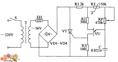
When the temperature of water is beyond the set temperature,the resistence of RT increases.It delays the time when VU outputs the trigger pulse in unit time.The conduction angle of VT decreases.The working voltage of EH decreases.The temperature of water decreases slowly.When the temperature of water is lower than the set temperature,VU outputs trigger pulse earlier.The conduction angle of VT increases.The working voltage of EH increases.The temperature of water goes up.It goes on and on.The water temperature of fish pool stays normal.
(View)
View full Circuit Diagram | Comments | Reading(378)
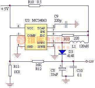
5v to 12v step-up circuit
Published:2011/6/16 5:12:00 Author:Borg | Keyword: step-up circuit
View full Circuit Diagram | Comments | Reading(2489)
the circuit of humidity indicator
Published:2011/6/13 7:44:00 Author:Ariel Wang | Keyword: humidity, indicator
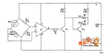
After the mains switch get through,the whole machine is conducted to work.When the humidity of seeding raising shed is at a normal level and the resistence of RS is at a high level,IC outputs low level .It is because the electric potential of the inverting input is higher than it of non-inverting input.VI stops.The red LED VL1 is not lighted.Y2 is conducted.The green LED VL2 is lighted.It indicates the humidity of shed is normal.If the humidity of seeding raising shed is at a high level ,then the resistence of RS is at a low level.When the amount of humidity is beyond the set value,IC outputs high level.It is because the electric potential of the non-inverting input is higher than it of inverting input.VI is conducted.VL2 is not lighted.It indicates the humidity of shed is over the normal amount.It reminds farmers to reduce the amount of humidity in shed by ventilation in time.
(View)
View full Circuit Diagram | Comments | Reading(551)
The frequency splitter adjusted by the potentiometer (CC4013 and CH3130)
Published:2011/6/21 9:47:00 Author:Borg | Keyword: frequency splitter, potentiometer
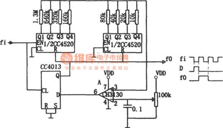
In the circuit, the D/A converter switches the input data into the voltage, and the voltage is compared with the reference voltage set by the potentiometer, then the output of the comparator is fed back to the reset terminal of the comparator, finally, we get the split pulse. The working method of the circuit is different from that of the feedback splitter of traditional counter, although the traditional way is suitable for solid integer splitting, the constant isn't easy to adjust. This circuit is specially suitable for conditions that need to change the splitting constant in a wide range. (View)
View full Circuit Diagram | Comments | Reading(673)
the circuit of the double hresholds temperature alertor(3)
Published:2011/6/20 6:34:00 Author:Ariel Wang | Keyword: double hresholds , temperature, alertor
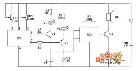
IC1 is the integrated circuit of intelligent temperature sensor.It is used for detecting temperature.When the temperature is appropriate(the temperature being detected is within the upper limit value and the lower limit value of the alarm temperature ),pin-6 of IC1 outputs low level.Pin-7 outputs high leve.V1 and V2 are stopped.VL1 and VL2 are not lighted.IC2 and V3 are not working.BL doesn't give a sound.When the detected temperature is lower than the lower limit value,pin-7 outputs low level from high level.V2 is conducted.VL2 is lighted.It indicates the detected temperature is low.At the same time,IC2 is conducted to work.The acoustics signal is amplified by V3.The driver BL gives alam sound.
(View)
View full Circuit Diagram | Comments | Reading(472)
The pulse widened device circuit of photoelectric couplers
Published:2011/6/28 7:47:00 Author:Borg | Keyword: widened device, photoelectric couplers
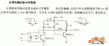
The pulse widened device of photoelectric couplers When we need to widen the narrow pulse, the figured circuit can be adopted. With the figured parameters, the pulse whose width is 3μs can be widened as the pulse of 1.2ms, as there is the passive feedback of the resistor of 100kΩ, so the output signal UA is more stable. (View)
View full Circuit Diagram | Comments | Reading(619)
the circuit of the double hresholds temperature alertor(2)
Published:2011/6/20 6:36:00 Author:Ariel Wang | Keyword: double hresholds, temperature , alertor
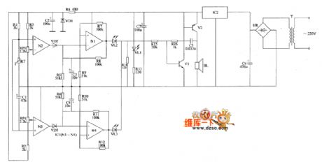
The 220V AC voltage is reduced by T,commutated by UR,filtered by C3 and regulated by IC2.It provides +6V voltage for amplifier circuit of temperature detect ,ultra-low frequency oscillator and sound warning circuit.When the controlled temperature is beyond the upper limit of the set temperature,the resistence of RT is decreased.N2 outputs low level as the reference voltage of non-inverting termina is lower than it of inverting termina .VD2 is stopped.The ultra-low frequency oscillator consists of N1,R5,R7~RiO and C3.VL2 is lighted.At the same time,super low frequency oscillation signal modulates the audiofrequency oscillator which consists of R14~R16,C3 ,VI and V2.The driver BL gives out buzz sound every now and then. (View)
View full Circuit Diagram | Comments | Reading(494)
The instrument amplifier circuit with the transformer as the separator
Published:2011/7/1 21:18:00 Author:Borg | Keyword: instrument amplifier, transformer
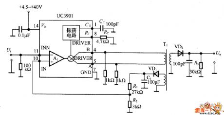
In the figure is the instrument amplifier circuit with the transformer as the separator, this is a circuit whose working voltage range is wide and the gains setting is easy. The input voltage is AM-modulated by UC3901 and added to the primary stage of the transformer T1, and then the input signal is recovered after it is detected by VD2 at the second stage. The modulating frequency of the circuit is decided by RT and CT, according to the parameter, which is 2MHz. The gain is AG=1+R2/1R=l+27kΩ/3kΩ=lO times. UC3901 is designed to be at the working state of the fault amplifier at the second stage of the switch stabilizer, whose working voltage range is +4.5~+40V.
(View)
View full Circuit Diagram | Comments | Reading(841)
The 2-line mains auto converting power supply device circuit
Published:2011/7/4 4:00:00 Author:Borg | Keyword: power supply, converting
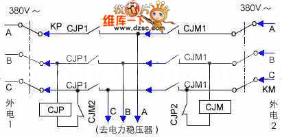
Generally, the 2-line supply device circuit has manual converting control, however, due to the bad weather in mountains, power-off often happens, and the people on duty are more than 100m far away from the power room, once one line is cut off, it will take a long time to inverse the power by people, the labor intensity is high, and the TV emitter and the 3 set of FM broadcasts are stopped, which affects the broadcast. This auto power converting equipment can convert power in 1/10S when one line of power is broken down suddenly, which can keep the broadcast out of effect. The whole equipment is cooperating with the power stabilizer(250KVA).
(View)
View full Circuit Diagram | Comments | Reading(590)
| Pages:1601/2234 At 2016011602160316041605160616071608160916101611161216131614161516161617161816191620Under 20 |
Circuit Categories
power supply circuit
Amplifier Circuit
Basic Circuit
LED and Light Circuit
Sensor Circuit
Signal Processing
Electrical Equipment Circuit
Control Circuit
Remote Control Circuit
A/D-D/A Converter Circuit
Audio Circuit
Measuring and Test Circuit
Communication Circuit
Computer-Related Circuit
555 Circuit
Automotive Circuit
Repairing Circuit