
Circuit Diagram
Index 1697
Medicinal automatic timing erythrocyte sedimentation rate shelf
Published:2011/6/24 8:17:00 Author:Nicole | Keyword: automatic timing, erythrocyte sedimentation rate, shelf
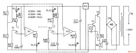
This medicinal automatic timing erythrocyte sedimentation rate shelf circuit is composed of power supply circuit, sound alarming circuit and timing circuit, it is shown in the figure 9-158.
The power supply circuit is made of power supply switch SO, power supply transformer T, rectifier quad UR, filter capacitor C13, C14 and three terminal regulator integrated circuit IC1.
The sound alarming circuit consists of transistors V1, V2, resistor R5, capacitor C13 and loudspeaker BL.
The 220V voltage is pressure released by T, it is rectificated by UR, it is filtered by C14, it is regulated voltage by IC1, one path provides IC2-IC4 with +12V work voltage, after divided voltage by R1, R2, the other path provides N1-N12's phase reversal input terminal with reference voltage.
(View)
View full Circuit Diagram | Comments | Reading(697)
Unfired bricks moisture detector 2
Published:2011/6/26 22:30:00 Author:Nicole | Keyword: Unfired brick, moisture, detector
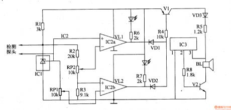
This unfired bricks detector circuit is composed of humidity detector probe, steady voltage reference voltage, comparator, switch circuit and acousto-optic alarm circuit, it is shown in the figure 8-76.
The comparator circuit is made of integrated circuit IC2 and resistors R2, R3, potentiometers RP1, RP2.
The switch circuit consists of switch tube V1, diodes VD1, VD2 and resistor R4.
The acousto-optic alarm circuit is composed of LEDs VL1, VL2, resistors R6, R7, music integrated circuit IC3, audio amplifier tube V2 and loudspeaker BL.
(View)
View full Circuit Diagram | Comments | Reading(1182)
Bearing fault detector 1
Published:2011/6/24 7:48:00 Author:Nicole | Keyword: bearing fault, detector
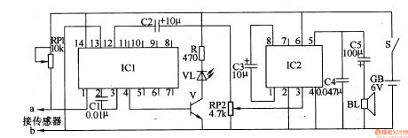
The bearing fault detector circuit is composed of bearing testing sensor, signal process circuit IC1, LED VL, transistor V, audio amplifier integrated circuit IC2, soudspeaker BL and some relevant resistor capacitor components, it is shown in the figure 8-78.
After the power supply switch S is turned on, IC1 works, its 4 foot and 12 foot all output high level, V is turned on, VL is lighted, then IC2's 3 foot has no input signal, loudspeaker BL does not phonate.
RP1 is used to adjust the sensitivity of signal process circuit.
RP2 is used to regulate the loudspeaker's output volume.
(View)
View full Circuit Diagram | Comments | Reading(684)
Bearing fault detector 2
Published:2011/6/24 7:57:00 Author:Nicole | Keyword: bearing fault, detector
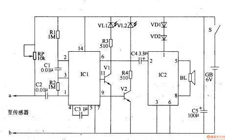
The bearing fault detector circuit is composed of bearing testing sensor, signal process circuit and acousto-optic circuit, it is shown in the figure 8-79.
The signal process circuit is made of input socket XS, sound control integrated circuit IC1, capacitors C1-C3, resistors R1, R2 and potentiometer RP.
The acousto-optic circuit consists of transistors V1, V2, LED VL1, VL2, audio power amplifier integrated circuit IC2, resistors R3, R4, capacitor C4, diode VD1, VD2 and loudspeaker BL.
The sensor's sensitivity can be changed by adjusting RP.
(View)
View full Circuit Diagram | Comments | Reading(834)
74 series digital circuit 74LS440/441 four 3-directions bus transceiver
Published:2011/6/26 21:35:00 Author:Nicole | Keyword: 74 series, digital circuit, bus transceiver
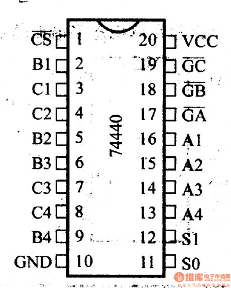
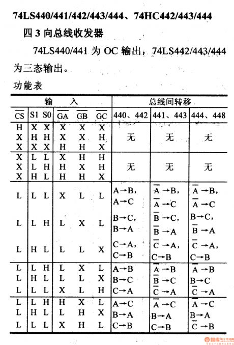
74LS440/441/442/443/444, 74HC442/443/444 four 3-directions bus transceiver
74LS440/441 is OC output, 74LS442/443/444 are there state output
The functional table
(View)
View full Circuit Diagram | Comments | Reading(827)
CMOS system power supply interface-DC switch circuit
Published:2011/6/20 19:13:00 Author:TaoXi | Keyword: CMOS, system, power supply, interface, DC, switch
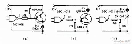
The CMOS system power supply interface-DC switch is as shown in the figure. Circuit (a) is the CMOS output circuit, it turns on and turns off the 14V, 80mA bulb circuit by using the small power transistor PNP Darlington MPSA65; circuit (b) uses the NPN Darlington MPAS13 high level to turn on the bulb; circuit (c) uses the CMOS output to drive the high sensitivity SCR 2N5060 directly. The high sensitivity SCR 2N5060 can be used in the extremely hard condition (-65℃), the maximum gate current is 35μA. It requires the CMOS to output the high level of 14.8V.
(View)
View full Circuit Diagram | Comments | Reading(1213)
IQS2404 button touch induction switch circuit
Published:2011/6/20 19:14:00 Author:TaoXi | Keyword: button, touch induction, switch
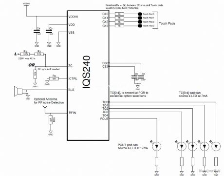
The IQS2404 button touch induction switch circuit (View)
View full Circuit Diagram | Comments | Reading(648)
6V to 24V motorcycle battery charger circuit
Published:2011/6/20 19:23:00 Author:TaoXi | Keyword: 6V to 24V, motorcycle battery, charger
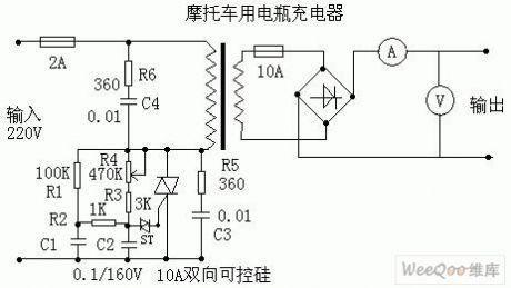
The circuit of this charger is very simple, the performance is stable and reliable, the adjustment range is wide; this circuit does not need the high-power high-current SCR and it can charge any 6V-24V batteries, the R6 and C4 make the load to approximate the resistance characteristics.
R1: 100K, R2: 1K, R3: 3K, R4: 470K (variable), R5: 360Ω, R6: 360Ω.
C1: 0.1uf / 160V, C2: 0.1uf / 160V, C3: 0.01uf / 600V, C4: 0.01uf / 600V.
ST: trigger two-way diode, two-way SCR: 10A/600V.
Transformer: about 100W, 220V/30V.
Rectifier bridge: 15A/100V.
Ammeter: 10A.
Voltmeter: 50V. (View)
View full Circuit Diagram | Comments | Reading(4626)
Battery (group) charging circuit with the adjustable charging voltage
Published:2011/6/20 20:22:00 Author:TaoXi | Keyword: Battery, group, charging circuit, adjustable charging voltage
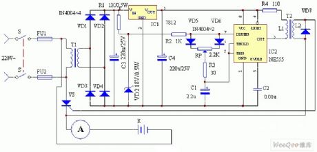
Working principle: The circuit working principle is as shown in figure 1. This circuit is composed of the power supply circuit, the trigger circuit and the main control circuit. The 220 city electricity is reduced by the power switch S-S' and the power transformer T1, and then it is rectified by the full wave rectifier circuit which is composed of the diodes VD1-VD4 to become the Pulse DC power source. One channel is limited by the resistance R1, and it is stabilized by the voltage stabilization diode DW to output the 18V trapezoidal wave synchronous manostat as the power supply of the delay link of the astable oscillator RC which is composed of the time base integrated circuit NE555 and the external components; another channel outputs the 12V stable power as the operating power supply of the trapezoidal wave synchronous power supply IC2.
(View)
View full Circuit Diagram | Comments | Reading(877)
CRT over-voltage protection circuit
Published:2011/6/20 21:46:00 Author:TaoXi | Keyword: CRT, over-voltage, protection
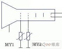
Because the distance between the poles of the CRT is very small, and also because some reasons of the production process, so if we add the ten thousand volt high voltage on the CRT's anode, there will be the jump-fire phenomenon between the anode and the other electrodes. In order to eliminate this phenomenon, some TVs install the disrharge tube on the CRT or use the metal clearance mode, but the two methods have poor reliability, if we use the ZnO voltage sensitive resistance, the effect will be good.
(View)
View full Circuit Diagram | Comments | Reading(600)
AC voltage stabilizer over-voltage and lightning protection circuit
Published:2011/6/20 21:54:00 Author:TaoXi | Keyword: AC, voltage stabilizer, over-voltage, lightning, protection circuit
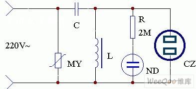
The application circuit of this device is as shown in the figure. Because the voltage of the rural power grid is not stabe, so we can make a simple AC magnetic saturation voltage device. The power input port of the AC voltage stabilizer is connected with a voltage sensitive resistance MY to prevent the impact of the TV set's overvoltage, and this makes the operating of TV more stable. If the AC voltage stabilizer works in the thunderstorm days, it has the lightning prevention function.
(View)
View full Circuit Diagram | Comments | Reading(1060)
Three-phase four-wire system power phase-lack protection circuit
Published:2011/6/20 22:16:00 Author:TaoXi | Keyword: Three-phase, four-wire, system, power, phase-lack, protection circuit
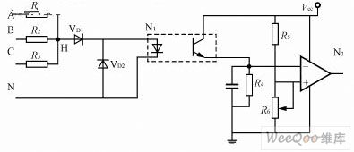
When the power supply is in the phase lack operating state, one limb of the rectifier bridge has no current, and other limbs will be damaged by the overcurrent, and the operating of inverter will be abnormal, so we must protect the phase lack. We usually use the current transformer or the electronic phase lack detection circuit to detect the phase lack of the power grid. Because the testing cost of the current transformer is high, and the volume is large, so we usually use the electronic phase lack detection circuit in the switch power supply. The simple electronic phase lack detection circuit is as shown in the figure. When the three-phase is balanced, the level of the R1~R3's node H is low, the light coupling output is near zero.
(View)
View full Circuit Diagram | Comments | Reading(765)
Relay closing indicating circuit
Published:2011/6/20 22:42:00 Author:TaoXi | Keyword: Relay, closing, indicating circuit
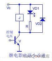
The relay is installed in the interior of the electrical equipment, the operating state is not intuitive, so the author makes some improvements which is as shown in the figure. The two ends of the coil are connected with the light-emitting diode VD1, when the control voltage is positive, the transistor conducts, the relay J closes, at the same time the light-emitting diode is turned on, this means the relay coil is coupled with the power. The light-emitting diode can be installed at the conspicuous place of the outer covering.
(View)
View full Circuit Diagram | Comments | Reading(627)
Relay driver circuit with the power voltage lower than the relay closing voltage
Published:2011/6/21 7:02:00 Author:TaoXi | Keyword: Relay, driver circuit, power voltage, relay closing voltage
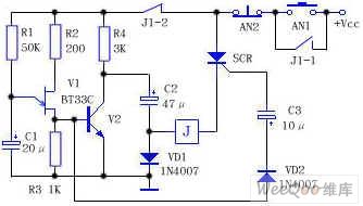
As the figure shows, the V1 is the single junction transistor BT33C, the relaxation type oscillator is composed of the R1, R2, R3 and C1, the SCR is the single-way SCR, after you press the button AN1, the circuit has the power, because the SCR has no trigger voltage, so it will not conduct, also the relay J will not work, the power supply charges the capacitance C2 to the power voltage through R4 and VD1 (Vcc-VD1 pressure drop). At the same time, the power supply charges the capacitance C1 through R1. After a few seconds, the voltage of C1 is charged to the trigger voltage of V1, so C1 discharges immediately through V1, a positive pulse is formed on R3 and this pulse adds to the base electrode of V2, so V2 conducts, the collector electrode of V2 (positive electrode of capacitance C2) is connected with the ground.
(View)
View full Circuit Diagram | Comments | Reading(668)
B0505LM-1W DC/DC converter application circuit
Published:2011/6/21 8:13:00 Author:TaoXi | Keyword: DC/DC, converter, application circuit
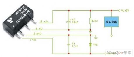
The B0505LM-1W series products are produced by the MORNSUN company, the B0505LM-1W series products are very suitable in this project, the B0505LM-1W is a 1000VDC subminiature DC/DC converter with good reliability, the input voltage is 5V, the output voltage is 5V, the power is 1W, the typical application circuit is as shwon in figure 1. Because this device has the 1000VDC isolation between the input and output, and the output short circuit time is 1 second, so it can resist the interference of the high frequency transient impulse.
By improving the technology, the reliability of the MORNSUN products are better and better. Meanwhile the quality engineer strictly controls the supplier selection and the incoming quality control (IQC).
Figure 1 The typical application circuit of the B0505LM-1W (View)
View full Circuit Diagram | Comments | Reading(1338)
Simple high & low frequency signal generator circuit
Published:2011/6/21 9:14:00 Author:TaoXi | Keyword: Simple, high, low, frequency, signal generator
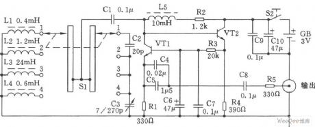
The simple high & low frequency signal generator circuit is as shown in the figure. You can change the inductance value of the LC resonance loop by using the band switch Sl, so we can change the frequency range of the high-frequency oscillation. This device has four stages:
The first stage is 0.4~2MHz;The second stage is 2~10MHz;The third stage is 9~45MNz;The fourth stage is 60~110MHz.
Components selection:
The VTl and VT2 use the NPN silicon tube (fT≥800MHz, β≥100) such as the 9018 and C535.etc. The resistance uses the 1/8W carbon membrane resistance. The capacitance C5 uses the monolithic capacitor, the other capacitances use the ceramic capacitor. The L2, L3, L4 and L5 use the high-frequency magnetic inductor, or you can wind it by yourself. The Ll uses the Φ0.6mm high strength varnished wire. The Sl uses the double-blade four-throw wave-band switch.
(View)
View full Circuit Diagram | Comments | Reading(1503)
The main circuit of the simple battery automatic constant current charging circuit
Published:2011/6/21 20:04:00 Author:TaoXi | Keyword: main circuit, simple battery, automatic, constant current, charging circuit
The main circuit of the simple battery automatic constant current charging circuit is as shown in the figure. It is composed of the transformer rectifier circuit, the constant current generating circuit, the charging detection circuit, the display circuit and the power supply circuit. In the main circuit, you should notice that the connection between the unit circuits must be accurately, and the overall arrangement must be reasonably.
(View)
View full Circuit Diagram | Comments | Reading(834)
Automatic charging detection circuit and the indicating circuit
Published:2011/6/21 20:12:00 Author:TaoXi | Keyword: Automatic charging, detection circuit, indicating circuit
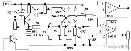
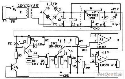
As the figure shows, the automatic power-off circuit is composed of the transistor VT2, the voltage follower A1, the voltage comparator A2, the resistors R4, R5, R6, R7, R8, R11 and the variable resistor RP1. When the charging begins, the voltage comparator outputs the high level, the VT1 and VT2 conduct, the LED indicator light turns on, the power charges the battery. You can preset the stage 1 of the change-over switch means to charge a battery, the stage 2 of the change-over switch means to charge two batteries, so you can realize to charge for the 1-4 batteries. When the batteries are full, the voltage comparator outputs the low level, the VT2 cuts off, the VT1 will not conduct, the LED turns off, the charging is over.
(View)
View full Circuit Diagram | Comments | Reading(677)
Transformer rectifier circuit and the power supply circuit
Published:2011/6/21 20:19:00 Author:TaoXi | Keyword: Transformer, rectifier circuit, power supply circuit
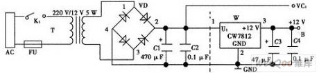
The transformer rectifier circuit and the power supply circuit is composed of the transformer, the diode bridge type circuit and the capacitance. The transformer uses the conventional iron core transformer and it changes the 220V AC electricity of the public power grid into the 12V AC electricity, and this 12V AC electricity is rectified and filtered by the diode bridge type circuit and the capacitance C1. The rectifier signal is led by VC1. If you add the three ports voltage stabilizer CW7812 and the capacitances C3 and C4 in the circuit, the whole circuit will be the voltage stabilization power supply circuit. The point B supplies the +12V DC voltage.
(View)
View full Circuit Diagram | Comments | Reading(1847)
220V AC changed into the 600V DC switch power supply circuit
Published:2011/6/21 20:30:00 Author:TaoXi | Keyword: 220V, AC, 600V, DC, switch, power supply

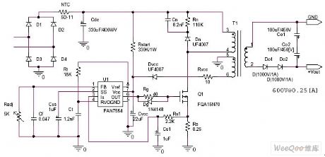
The high voltage boost power circuit: the 220V AC changed into the 600V DC switch power supply circuit.
Specifications:
Input voltage=220Vac±10%50/60Hz
Output voltage=0~600Vdc 0.25A
Switch frequency: 70~100kHz
Design guidelines:
In the DCM mode, the output power is 200W
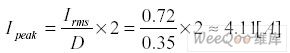
The degradation situation continuous current mode calculation formula of the input RMS current is:
If the best operating duty ratio is set to D=0.35, the calculation formula of the input peak current is:
So the voltage detection voltage level limit of the FAN7554 is 1.5V.
(View)
View full Circuit Diagram | Comments | Reading(6633)
| Pages:1697/2234 At 2016811682168316841685168616871688168916901691169216931694169516961697169816991700Under 20 |
Circuit Categories
power supply circuit
Amplifier Circuit
Basic Circuit
LED and Light Circuit
Sensor Circuit
Signal Processing
Electrical Equipment Circuit
Control Circuit
Remote Control Circuit
A/D-D/A Converter Circuit
Audio Circuit
Measuring and Test Circuit
Communication Circuit
Computer-Related Circuit
555 Circuit
Automotive Circuit
Repairing Circuit