
Circuit Diagram
Index 1756
electric power blender circuit diagram
Published:2011/5/11 1:46:00 Author: | Keyword: electric, blender
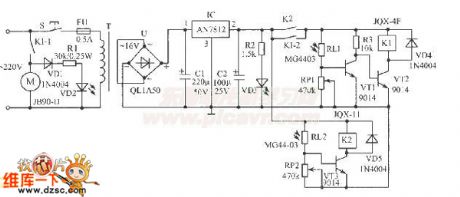
Electric power blender is usually used in industrial and mining enterprises.Because the mixed material produce scent and powder,workers are not suitable to contact too close.A light controlled electric blender(or other circuit )circuitshown in the figure, uses common flashlight beam as remote control instruction, which can control blender operation in 10m.This circuit can be enclosed in a plastic box,which is used very convenient.
components and parts:IC selects AN7812 three-terminal voltage IC.VT1~VT3 uses 9014 dynatron.RL1 and RL2 uses MG44-03 type plastic resin encapsulated photosensitive resistant,or selects other common photosensitive resistant (light 5KΩ,dark ≥1MΩ) instead.VD2,VD3 are LEDs.T is 8W~10W power transformer.Other selected components and parts are shown as figure.
(View)
View full Circuit Diagram | Comments | Reading(6805)
autocycle flasher principium circuit diagram
Published:2011/5/11 1:46:00 Author: | Keyword: autocycle, flasher principium
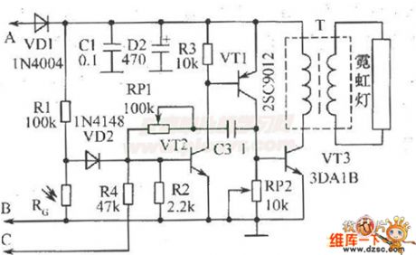
Neon light flasher assumed on autocycle back brand circuit diagram and work principle:assume a neon flashershown as the figureon autocycle back brand, which can increase safety in night,bring attention of the following vechiles, and flick when the autocycle brake.This set takes a neon tube that can justcircle the number plate,illuming it at night.VT1 and VT2 form a complementary instable multi-vibrator.BP1 and C3 decide vibrator work frequency.Signal voltage on RP2 is amplified by VT3 to drive step-up transformer T,then secondary induce high voltage to make the neon light.
elements select:expect indicated elements type,photosensitive resistant can use M45 series,requiring dark resistant>1MΩ,light resistant<10KΩ;pulse transformer T can select E12 type magnetic coreMXQ-2000,primary using 45 circle Φ0.51mm lacquered wire ,secondary using about 1500 circle Φ0.21mm high strength lacquered wire.
(View)
View full Circuit Diagram | Comments | Reading(1123)
simple and practical Boost circuit diagram
Published:2011/5/11 1:47:00 Author: | Keyword: simple, practical, Boost
View full Circuit Diagram | Comments | Reading(758)
xinfei BCD-245 fridge circuit diagram
Published:2011/5/11 1:45:00 Author: | Keyword: fridge, circuit
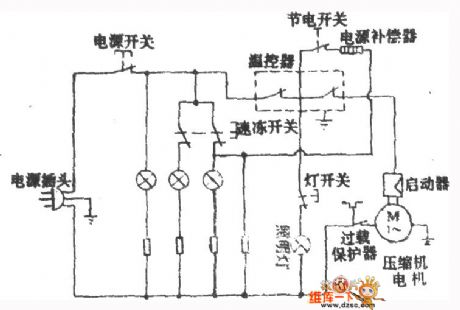
View full Circuit Diagram | Comments | Reading(606)
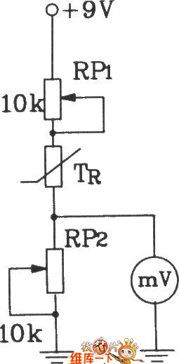
T-121 temperature sensor forming electronic thermometer circuit diagram
Published:2011/5/16 8:51:00 Author:Lena | Keyword: electronic thermometer, temperature sensor
View full Circuit Diagram | Comments | Reading(1057)
MHZ LED Pulse Modulation Circuit Diagram
Published:2011/5/11 1:45:00 Author: | Keyword: MHZ, LED, Pulse Modulation
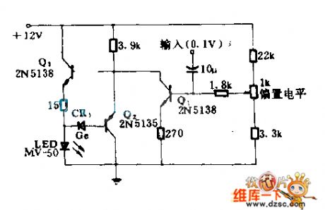
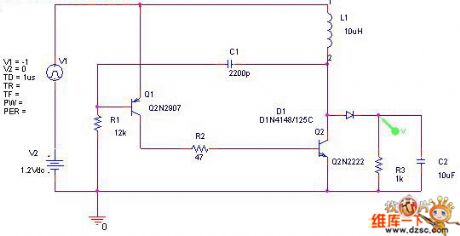
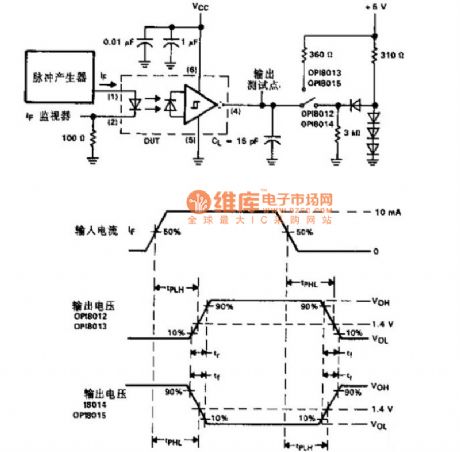
Thecircuit is a GaAsP LED which is quickly switch-on to supply required low driven impedance.The LED can be used as high speed pulse lamp-house in fiber or other light.Q1 supplys volts d.c. and information for Q3(follower).Q2 detects output current, and limits it at about 30mA.The max switch-on time is 12ns.
(View)
View full Circuit Diagram | Comments | Reading(1074)
CXD3008-the integrated circuit of digital signal and servo processing
Published:2011/6/13 21:27:00 Author:Borg | Keyword: integrated circuit, digital signal, processing
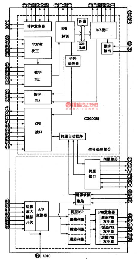
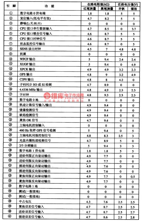
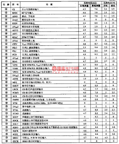
1.Function featuresCXD3008 can do demodulation to the CD, VCD and SVCD signals read out by its laser head, after handling them with super fault correcting algorithm and 32KBAM inside it, the circuit will output them as the form of CD data; in addition, it also digitally processes the signals of focus errors, tracking errors, feed errors and spindle errors in the way of repeated servo software control and wide seizing, and does auto control and auto offset control to servo circuits.
2.pin functions and data
(View)
View full Circuit Diagram | Comments | Reading(802)
The timely disinfecting, deodorizing and sterilizing circuit of 555 fridge
Published:2011/6/13 21:29:00 Author:Borg | Keyword: disinfecting, deodorizing, sterilizing
This timely disinfecting, deodorizing and sterilizing circuit of fridge can self-start and then generate ozone and air negative ions when the fridge door is open, and disinfects, deodorizes and sterilizes the inside of the fridge, when the time is over, it will automatically stops working, which is effective.The deodorizing circuit includes AC step-down voltage-steady circuit, light control timer switch circuit, high frequency oscillator and high frequency electricity discharger, etc, see as Figure 13-24.
The AC current is firstly stepped down by the capacitor of C1, and then is filtered by rectifier of C2 after passing D1~D4, finally comes out from the 3-terminal stabilizer as a +12V voltage and provides with working power supply for IC2 and IC3. (View)
View full Circuit Diagram | Comments | Reading(615)
The simple temperature control circuit of 555
Published:2011/6/13 21:30:00 Author:Borg | Keyword: temperature control
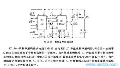
IC2 is an integrated circuit LM567 of frequency decoding, which consists a frequency decoder with RP1, C3 and so on,and its central frequency f0 is set as the central frequency of audio oscillator at the regulated temperature. When the outside temperature is too low, the difference between the vibration frequency and the regulated central frequency (f0) is noticeable, and LM567 doesn't react to the input signal, and its output terminal is in high LEV, the relay(K) is still. When the outside temperature reaches the regulated value, the central temperatures of IC1 and IC2 are the same, and IC2 decode reliably, the output point of LM567 is in a low LEV, K closes to cut off the power of the controlled equipment. (View)
View full Circuit Diagram | Comments | Reading(1158)
The talk back circuit of phones
Published:2011/6/13 21:33:00 Author:Seven | Keyword: talk back
The turnratio of the step-up transformer Tis 1:25, which is coordinating with the LM380 gain of 50, then the gain of all the circuit is 1250. The resistor R0 provides with common module sound volume control. LM380 is a sound frequency integrated amplifier, which has the internal gain of 50(34dB), and the output can automatically base on the half of the power supply voltage, the input stage can engage in DC coupling or AC coupling according to the need. The output stage has short circuit current limitation and heat cutting off protection circuit. To application, the internal characters can minimize the number of the external elements. (View)
View full Circuit Diagram | Comments | Reading(834)
The thermocouple temperature/frequency converter circuit (02)
Published:2011/6/10 3:45:00 Author:Seven | Keyword: thermocouple, temperature/frequency converter
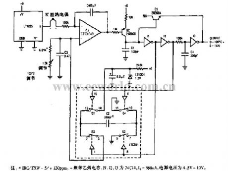
Notes: *IRC/TRW -5/+120PPM, +polystyrene capacitor, I1,I2 and I3 are the 74C14, Is=360μA, the voltage of the power supply is 4.5v~10v. (View)
View full Circuit Diagram | Comments | Reading(775)
Sound circuit: TA8211AH
Published:2011/6/10 1:31:00 Author:Seven | Keyword: Sound circuit
This circuit is from Changhong C2588 TV color1-pin:2.1v----external capacitor of left channel negative feedback external;2-pin:2.2v----left channel signal input;3-pin:0v----earth; 4-pin:2.2v----right channel signal input; 5-pin:2.1v----external capacitor of right channel negative feedback external;6-pin:8.2v----power supply wave filter; 7-pin:12v----right channel signal output; 8-pin:2.2v----empty; 9-pin:24v----power supply; 10-pin:0v----earth(power amplifier);11-pin:2.2v-empty;12-pin:12v----left channel signal output (View)
View full Circuit Diagram | Comments | Reading(531)
Multifunction Charger Four
Published:2011/5/19 8:08:00 Author:Michel | Keyword: Multifunction Charger Four
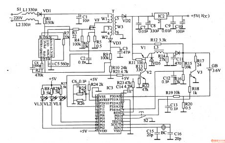
The multifunction charger introduced in the example takes advantage of switching power circuit and microprocessor (singlechip)control circuit with overcurrent and overvoltage protection functions.It can charge nickel-hydrogen and Lithium-ion rechargeable batteries.Circuit's Work PrincipleThis charger is composed of mains switch,S1,switching power circuit,control circuit,charge circuit and discharge circuit and it is showed as the picture 5-66.The switching power circuit consists of switch oscillation IC ,IC1,field effect transistor,VF,induction coil,L1,commutation diode,VD1-VD3,LED,VL1-VL3,control button,S2,quartz tuning folks,BC and surrounding resistor-capacitor unit. (View)
View full Circuit Diagram | Comments | Reading(1717)
Optocoupler Switch Timing Circuit
Published:2011/5/13 21:08:00 Author: | Keyword: Optocoupler Switch, Circuit
View full Circuit Diagram | Comments | Reading(1245)
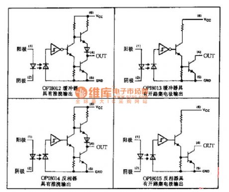
Application Circuit of Optocoupler Series
Published:2011/5/13 21:06:00 Author: | Keyword: Optocoupler Series, Application Circuit
View full Circuit Diagram | Comments | Reading(1425)
Typical Application Circuit of M54123 Intergrated Circuit
Published:2011/5/16 20:54:00 Author:Michel | Keyword: Application Circuit , Intergrated Circuit
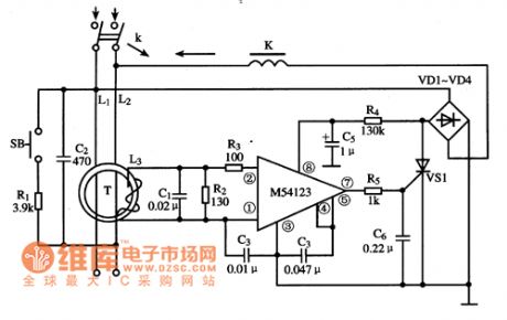
Typical Application Circuit
Typical application circuitof leakage protecter composed of M54123 IC is showed as above.
Picture:Typical Application Circuit of M54123 Intergrated Circuit
Note:China's homegrown part number of M54123 IC is SF4123 and they can be used interchangeably directly.
(View)
View full Circuit Diagram | Comments | Reading(1665)
The Inner Circuit Pane Circuit Diagram of M54123 IC
Published:2011/5/16 20:55:00 Author:Michel | Keyword: IC, Inner Circuit Pane, Ciruit Diagram
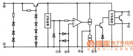
Functions and Features
M54123 IC is composed of voltage stabling circuit,voltage reference circuit,differential amplifier,lockout and output circuit etc.Its major features are as follows.
Firstly,supply voltage range is from 12-28V.Line voltage could work normally when it changes from 120V to 280V,that's to say, leakage circuit can be swtiched off reliably when line voltage is at the low point.
Secondly,operation voltage is low(4-9mv),so its zero-sequence current mutual inductor volume is small.
Thirdly,leakage operation current is steady becuase there is voltage reference.
Fourth,the actual requirements can be meet completely as the operation time less than 0.5s.The Inner Circuit Pane Circuit Diagram of M54123 IC is showed as above.
Picture:The Inner Circuit Pane Circuit Diagram of M54123 IC (View)
View full Circuit Diagram | Comments | Reading(1178)
Typical Application Circuit of M52340SP IC
Published:2011/5/16 7:13:00 Author:Michel | Keyword: IC, Application Circuit
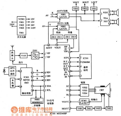
Typical Application Circuit
The typical application circuit of M52340SP IC shows as the picture.Konka F2136 color TV is a typical application example.
Picture:Typical Application Circuit of M52340SP IC
Note:If both image and sound accompaniment go wrong meanwhile ,we shuold check 38MHz intermediate sequancy signal which is high sequancy singal at first but changed into intermediate then whether it is added to ⑥ and ⑦ feet.The M52340SP circuit will be checked if the signal is normal.Typical Application Circuit of M52340SP IC (View)
View full Circuit Diagram | Comments | Reading(1182)
The Inner Circuit Pane Circuit of M52340SP IC
Published:2011/5/18 2:31:00 Author:Michel | Keyword: IC, Circuit Pane Circuit Diagram
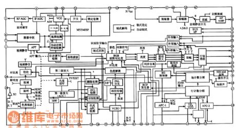

Functions and Features
M52340SP IC has IC bus control circuit,which simpilies many outer components,circuit and makes productlines more rational.That is to say,the intergrated circuit contains wave-trap,high pass filter,luminance delay line,RGB clamping circuit and adopts PLL detecting system which can deal wtih image intermediate frequency and sound intermediate frequency without sting coil.In addition,it uses delay line control,that is to say,it can recognise kinds of color tlevisions'signal frequency and field frequency.Besides,it uses line and frequency demultiplication.
(View)
View full Circuit Diagram | Comments | Reading(1255)
Typical Applied Circuit of M50560-200P IC
Published:2011/5/16 2:42:00 Author:Michel | Keyword: IC, Applied Circuit
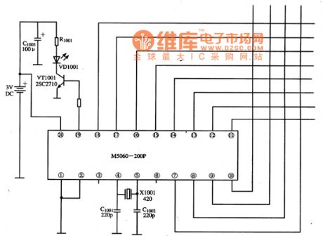
Typical Application Circuit
The remote control applied circuit composed of M50560-200P IC is showed as the picture.
Picture:Typical Application Circuit of M505060-200P IC (View)
View full Circuit Diagram | Comments | Reading(1657)
| Pages:1756/2234 At 2017411742174317441745174617471748174917501751175217531754175517561757175817591760Under 20 |
Circuit Categories
power supply circuit
Amplifier Circuit
Basic Circuit
LED and Light Circuit
Sensor Circuit
Signal Processing
Electrical Equipment Circuit
Control Circuit
Remote Control Circuit
A/D-D/A Converter Circuit
Audio Circuit
Measuring and Test Circuit
Communication Circuit
Computer-Related Circuit
555 Circuit
Automotive Circuit
Repairing Circuit