
Circuit Diagram
Index 1758
Three-phase electromotor low-speed operation circuit
Published:2011/6/1 21:12:00 Author:Christina | Keyword: Three-phase, electromotor, low-speed, operation
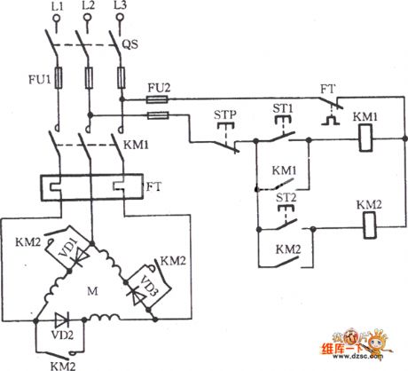
The Three-phase electromotor low-speed operation circuit is as shown:
Some times we need the electromotor to work in the low-speed operation state, and we do not want to use the mechanical reducer, so we can use this circuit to achieve. As the figure shows, we connect the VD1~VD3 with the three-phase winding in series, and add the normally open contact point KM2 to the three-phase winding, then we press ST1, KM1 will close, VD1, VD2 and VD3 connect with the winding, the electromotor M will operate in the low-speed state. IF we press ST2, KM2 closes to short connect the VD1, VD2 and VD3, the electromotor M will run at full speed with the rated voltage. (View)
View full Circuit Diagram | Comments | Reading(763)
Water level indicator circuit (5)
Published:2011/6/7 6:13:00 Author:Christina | Keyword: Water level, indicator
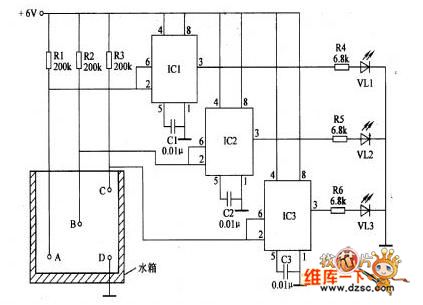
The water level indicator uses the LED to indicate the three stages water level of high, medium and low, and it can be used in wide range of water level indication applications such as the water tank, the pool, the boiler and the underground wells.
The circuit working principle: the water level indicator is composed of the water level electrodes A-D, the resistors Rl-R6, the capacitors Cl-C3, the time base circuits ICI-IC3 and the LEDs VLl-VL3, as the figure shows.
When there is no water in the tank, the +6V voltage adds to the pin-2 and pin-6 of the ICl-IC3 getsthrough Rl-R3, so pin-2 and pin6 have the high electrical level, pin-3 of ICl-IC3 output the low electrical level, VLl-VL3 will not turn on.
(View)
View full Circuit Diagram | Comments | Reading(2035)
50MH2 Photoelectric Demodulation Circuit
Published:2011/5/26 9:30:00 Author:Robert | Keyword: 50MH2, Photoelectric, Demodulation
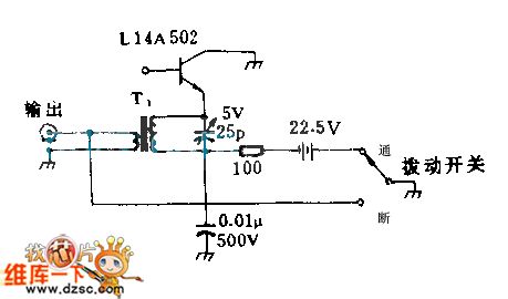
The parallel tuned method can be used in the single GE type photodiode circuit in the picture. When the parallel photodiodes have five, it is required to use the series tuned method. If the tuned capacitance uses its 0PF, the frequency response could be about 00MHz. T1's primary stage is 2 laps and its secondary stage is 7 laps, which wind around the high-frequency plastic core.
(View)
View full Circuit Diagram | Comments | Reading(591)
Time Delay Shutdown Circuit
Published:2011/5/27 7:59:00 Author:Robert | Keyword: Time Delay, Shutdown

The leftmost is RC time delay circuit and discharging diode. The middle is the circuit set for shutdown and you can regard it as a power supply. The rightmost circuit is used for simulate audio signals.
(View)
View full Circuit Diagram | Comments | Reading(1249)
Low Noise 20MHz Wideband Amplification Circuit
Published:2011/5/17 5:44:00 Author:Robert | Keyword: Low Noise, 20MHz, Wideband, Amplification
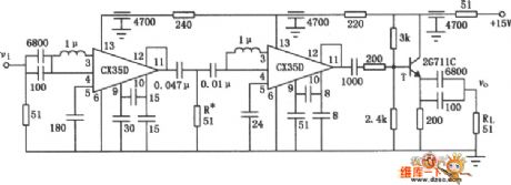
The Low Noise 20MHz Wideband Amplification Circuit is shown in the picture in the picture. This wideband amplification is made up by two CX35D, and its main technical specifications is: bandwidth 10~200MHz; when RL=500Ω the voltage gain is Av>=80; the undistorted output is Vo>=500mV, andthe short noise is less than 40uV for the equivalent toinput port.
(View)
View full Circuit Diagram | Comments | Reading(531)
Infrared Reflective Driving Distance Reminder Circuit
Published:2011/5/17 5:40:00 Author:Robert | Keyword: Infrared Reflective, Driving Distance, Reminder
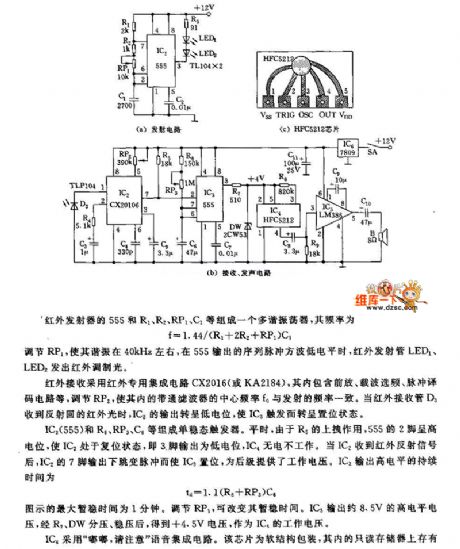
The picture (a) is transmitter circuit. The picture (c) is HFC5212 chip. The picture (b) is receiver and sound circuit.
The infrared transmitter's 555 and R1, R2, RP1, C1 etc. make up a multivibrator with frequency of f=1.44/(R1+2R2+RP1)C1.
By adjusting RP1 to make the oscillation at about 40kHz, the infrared launch tube LED1, LED2 would have infrared modulated light when the sequence pulses square wave from 555 is low voltage level.
The infrared receiver uses the infrared special integrated circuit CX2016 (or KA2184) which has front amplifier, carrier frequency selection, pulse decoder circuit and so on. By adjusting RP2 to make its internal bandpass filter's central frequency be the same with transmitter frequency. When the infrared receiver tube D3 has received the reflected infrared light, IC2's output voltage becomes low voltage level to trigger the IC3 to be set mode.
(View)
View full Circuit Diagram | Comments | Reading(742)
Multiplex Switchig Method Driving Display Circuit
Published:2011/5/17 5:52:00 Author:Robert | Keyword: Multiplex Switching Method, Driving, Display
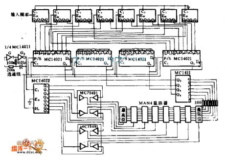
This circuit uses the battery to supply power. It takes a decode driver to drive the MAN-4 displayer'sseveral nixietubes one by one through the multiplex method, which can reduce the battery's power consumption. Because the readings saw by the human eye in the whole show cycle is still preserved impressions, it looks like the displayer being with a continuous display. The peak current of the displayer is 20mA, but every nixietube's electrified time is just 12.5% of the whole display cycle time. The four MC1402 8-bit shift registers lock and store the value caculated by the MC14515 counter and complete the multiplex switching function.
(View)
View full Circuit Diagram | Comments | Reading(657)
Automatically Illuminating Doorbell Circuit
Published:2011/5/17 5:53:00 Author:Robert | Keyword: Automatically Illuminating, Doorbell
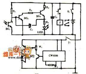
It's difficult to find the doorbell button when at night and the veranda has no light, especially for the visitors who come firstly and they could only knock the door. If the doorbell button switch has been installed a LED which could automatically illuminating at night and automatically closed during the day, it would be convenient for visitors. When the power switch K1 is connected, the phototransistor triode BG1's resistance would be low because of the light during the day, and BG2 base voltage would be low to make BG2, BG3 close. So the circuit would stop working and the LED would not illuminate.
(View)
View full Circuit Diagram | Comments | Reading(557)
Stepper Motor Typical Application Circuit
Published:2011/5/19 6:15:00 Author:Robert | Keyword: Stepper Motor, Typical Application
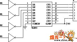
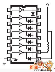
The ULN2003A type high-voltage large-current darlington transistors array circuit's typical application circuit diagram is shown in the picture below. The clamping diode is used for protecting the integrated circuit from been punctured by the EMF when the coil is connected or disconnected. It can be seen that this circuit's application is very simple.
The stepper motor typical application circuit is shown below.
(View)
View full Circuit Diagram | Comments | Reading(1006)
A Driving Circuit For Driving LED
Published:2011/5/18 21:47:00 Author:Robert | Keyword: Driving, LED

This circuit converts the single port's input signal to balanced differential driving signal and then this signal is send to 75Ω transmission line. The line's other port is connected to LED which is used as the input of optical coupling receiver. The phase reverser A changes the logic 1 to be logic 0 to make the Q1 connected and make B's output be 1. And the Q2 is disconnected and D's output becomes 0. So the logic 1 means that the Q2 borrows current from the transmission line and the LED and then the door D's output port absorbs the current. Or, Q2 would lend current to the transmission line and B absorbs the current, then D1 is connected to make the optical coupling receiver OC1's LED disconnected.
(View)
View full Circuit Diagram | Comments | Reading(700)
Typical Fan-Use Electronic Speed Governor Circuit
Published:2011/5/19 22:25:00 Author:Robert | Keyword: Fan-Use, Electronic, Speed Governor
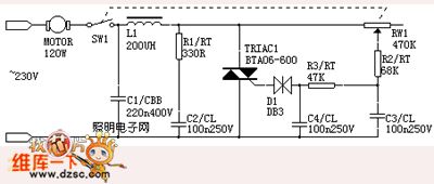
Most traditional fan speed governors are designedwith the capacitive voltage divider method. This method makes their adjustable gear stages less. By using the electronic control method shown in the picture below, it can get stepless speed regulating results. For the control to inductive fan it must make the bidirectional thyristor in parallel with a rc buffer network to limit the voltage rising rate (dv/dt). The c2 in the picture is used to limit the value beyond bidirectional thyristor's dv/dt value. The r1 is used to limit the c2's impact current when the thyristor is connected, and also it would weaken the damping oscillation between c2 and ll.
(View)
View full Circuit Diagram | Comments | Reading(1008)
Optocoupler SPDT Switch Circuit
Published:2011/6/7 18:48:00 Author:Robert | Keyword: Optocoupler, SPDT Switch
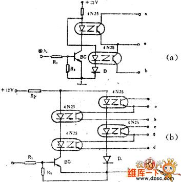
The optocoupler SPDT switch circuit is shown in the picture below.The picture (a) is SPDT switch circuit and the external connected diode D's function is to assure the od group channels connected and ob group channels disconnected when inputting positive pulse signal. The picture (b) is DPDT switch circuit. When there is no input signal, the BG is disconnected. The ob and od groups are disconnected and the oa and oc groups are connected. When the BG is connected (when having input signal), ob and od groups are connected and oa and oc groups are disconnected. They are suit in automatic control use and remote control equipment use.
(View)
View full Circuit Diagram | Comments | Reading(1836)
Small Emergency Light Circuit With Battery Protection
Published:2011/6/7 18:49:00 Author:Robert | Keyword: Emergency Light, Battery Protection
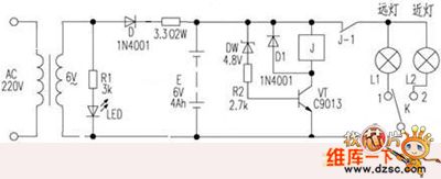
When the battery's output voltage is normal, the dw is punctured, vt is connected and also the relay is connected. The high beam or low beam light can be controlled by k to work. When the battery voltage is lower than 5.4V, the dw is disconnected to make the vt disconnected and the j open. The high beam or low beam light can not work continuously, so e stop discharging. This could protect the battery efficiently.
(View)
View full Circuit Diagram | Comments | Reading(820)
light-emitting diode voltage measurement circuit
Published:2011/5/11 3:16:00 Author:Christina | Keyword: light-emitting diode, voltage measurement
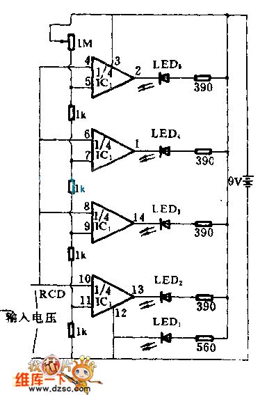
This circuit uses the LED to indicate (View)
View full Circuit Diagram | Comments | Reading(762)
RTL/TTL Probe Circuit
Published:2011/5/27 7:56:00 Author:Robert | Keyword: RTL, TTL, Probe
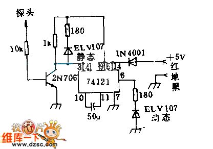
The static LED indicates the logic voltage level of the probe along its side. The dynamic LED's lighting indicates that there is a positive pulse or 1 pulse in the probe test port. Even the time is short while the pulse appearing, itcan still see the LED's lighting because this circuit has extended the pulse width to about 50ns. The pulse-extending device requires the input pulses is 100ns, 4V at least. The 1N4001 diode is used to prevent the damage caused by opposite connection of the power cord.
(View)
View full Circuit Diagram | Comments | Reading(687)
INA166 Signal And Power Supply Basic Connection Circuit
Published:2011/6/7 18:49:00 Author:Robert | Keyword: Signal, Power Supply, Connection
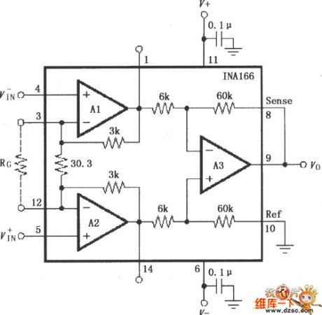
The INA166 Signal And Power Supply Basic Connection Circuit is shown in the picture below. The chip power supply port needs a 0.1uF tantalum capacitor for filtering. When in PCB layout it should make the tantalun capacitor as close to the chip power supply foot as possible. The output voltage detecting port Sense's connection and basic port Ref's connection must be connected with low resistance to assure high CMRR. If there is a 5Ω resistance in series it could reduce the CMRR. Its internal fixed gain is 2000. The input stage A1 and A2's gain is 200. The output stage A3's stage is 10. The amplifier gain can be changed by adding a gain-setting resistance RG between 3 foot and 12 foot. The gain would be G=2000+60000/RG.
(View)
View full Circuit Diagram | Comments | Reading(702)
Voice Modulation Optical Transmitter Circuit
Published:2011/5/27 7:57:00 Author:Robert | Keyword: Voice, Modulation, Optical, Transmitter
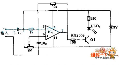
This circuit uses an operational amplifier and a transistor. According to the amplitudeof sound pickup device's output signal, it would do the amplitude modulation to the LED after its amplification. This circuit can be used in normal audio devices by optical receiver devices.
(View)
View full Circuit Diagram | Comments | Reading(2628)
Automatical Lighting Lamp Circuit Composed Of Photoresistor
Published:2011/5/27 7:58:00 Author:Robert | Keyword: Automatical, Lighting, Lamp, Photoresistor
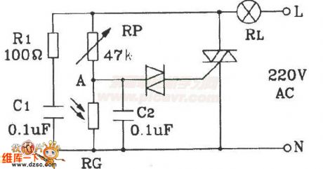
The Automatical Lighting Lamp Circuit Composed Of Photoresistor is widely used in hospital, students apartments corridor and puclic places. It would not light during the day and would light during the night.
(View)
View full Circuit Diagram | Comments | Reading(868)
Buzzer circuit
Published:2011/5/19 18:28:00 Author:Christina | Keyword: Buzzer
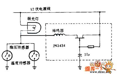
You can not judge if the engine monitoring indicator is turned on in day time, so you can use the buzzer circuit to compensate this shortage. Every time you start the engine, JFET 2N5434 will be conducted at 7 seconds delay time, so in the process of start the car and increase the hydraulic, the buzzer will not ring; at this time the indicator light monitors the oil pressure sensor and the engine temperature sensor. The whole circuit can beinstalled in the abandoned buzzer plastic shell of the bridge.
(View)
View full Circuit Diagram | Comments | Reading(878)
Single oscilloscope display device circuit
Published:2011/5/19 18:30:00 Author:Christina | Keyword: Single oscilloscope, display device
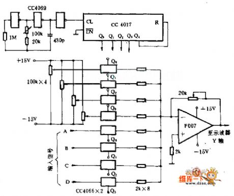
This display device uses the singleline oscilloscope to display the 4-channel continuous signal to compare the time relationship of different signals.
CC4017 is the oscillator and counter, it forms the 4 beats circuit and controls 4 pairs of analog form to connect them in turn. You can add the adjustable DC level and the one channel signal to each pair of analog switch, the signal will be mixed by the adder which is composed of the operational amplifier, and issent to the Y-axis of oscilloscope. Because the signals correspond to the different DC levels, so the oscilloscope can separate the 4 channels of signals.
(View)
View full Circuit Diagram | Comments | Reading(859)
| Pages:1758/2234 At 2017411742174317441745174617471748174917501751175217531754175517561757175817591760Under 20 |
Circuit Categories
power supply circuit
Amplifier Circuit
Basic Circuit
LED and Light Circuit
Sensor Circuit
Signal Processing
Electrical Equipment Circuit
Control Circuit
Remote Control Circuit
A/D-D/A Converter Circuit
Audio Circuit
Measuring and Test Circuit
Communication Circuit
Computer-Related Circuit
555 Circuit
Automotive Circuit
Repairing Circuit