
Circuit Diagram
Index 242
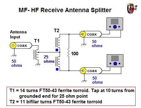
MF-HF receive antenna splitter
Published:2012/12/13 21:41:00 Author:muriel | Keyword: MF-HF, receive antenna, splitter

View full Circuit Diagram | Comments | Reading(4622)
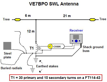
Outdoor MF and HF Antenna
Published:2012/12/13 21:38:00 Author:muriel | Keyword: Outdoor , MF and HF, Antenna
View full Circuit Diagram | Comments | Reading(1514)
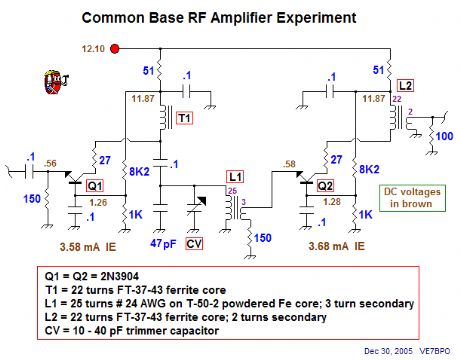
one RF amp
Published:2012/12/13 21:34:00 Author:muriel | Keyword: one RF amp
View full Circuit Diagram | Comments | Reading(786)
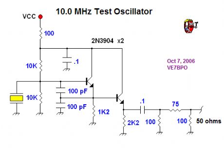
10.0 MHz crystal oscillator
Published:2012/12/13 21:33:00 Author:muriel | Keyword: 10.0 MHz , crystal oscillator
View full Circuit Diagram | Comments | Reading(3936)
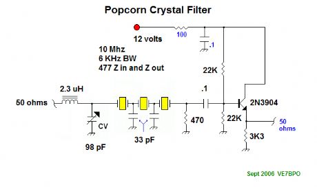
popcorn crystal filter
Published:2012/12/13 21:33:00 Author:muriel | Keyword: popcorn crystal filter
View full Circuit Diagram | Comments | Reading(1161)
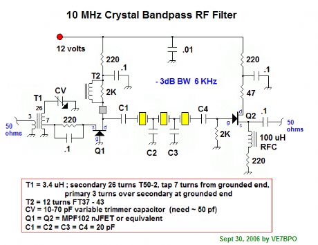
10MHz crystalk bandpass RF filter
Published:2012/12/13 21:32:00 Author:muriel | Keyword: 10MHz, crystalk bandpass, RF filter
View full Circuit Diagram | Comments | Reading(1567)
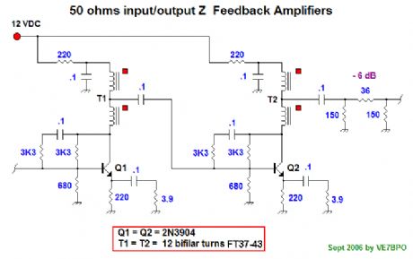
Feedback amplifiers
Published:2012/12/13 21:31:00 Author:muriel | Keyword: Feedback amplifiers
View full Circuit Diagram | Comments | Reading(849)
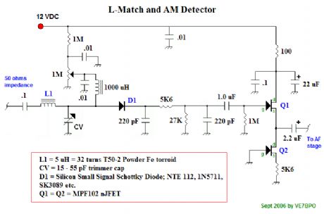
L-Match AM Detector
Published:2012/12/13 21:30:00 Author:muriel | Keyword: L-Match, AM Detector
View full Circuit Diagram | Comments | Reading(1807)
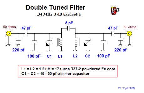
10 MHz, double tuned RF band pass filter
Published:2012/12/13 21:30:00 Author:muriel | Keyword: 10 MHz, double tuned, RF band, pass filter
View full Circuit Diagram | Comments | Reading(3997)
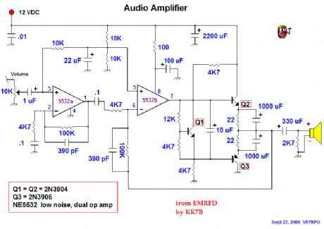
Audio Amplifier
Published:2012/12/13 21:29:00 Author:muriel | Keyword: Audio Amplifier
View full Circuit Diagram | Comments | Reading(0)
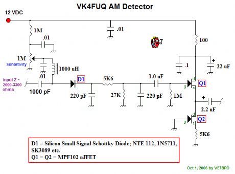
VK4FUQ AM detector
Published:2012/12/13 21:28:00 Author:muriel | Keyword: VK4FUQ , AM detector
View full Circuit Diagram | Comments | Reading(1806)
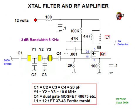
XTal Filter and RF Amplifier
Published:2012/12/13 21:27:00 Author:muriel | Keyword: XTal Filter, RF Amplifier
View full Circuit Diagram | Comments | Reading(1574)
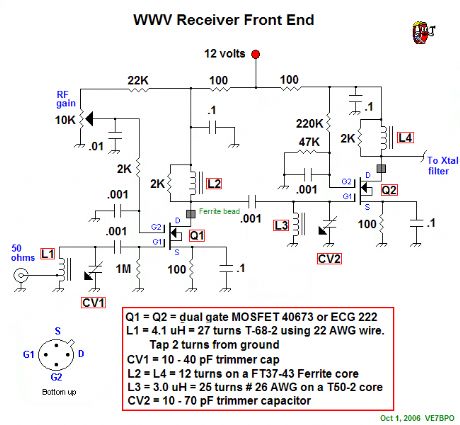
Receiver Front End
Published:2012/12/13 21:26:00 Author:muriel | Keyword: Receiver Front End
View full Circuit Diagram | Comments | Reading(883)
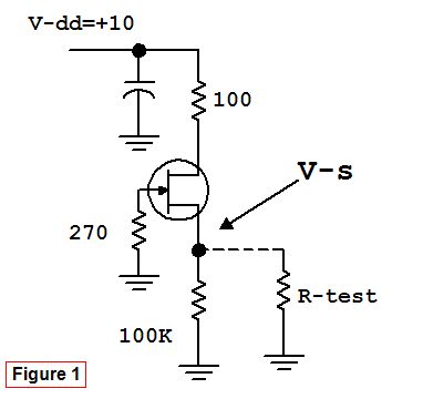
Experiments with JFET Biasing
Published:2012/12/13 21:25:00 Author:muriel | Keyword: Experiments, JFET Biasing
View full Circuit Diagram | Comments | Reading(696)
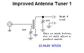
Antenna Tuner 4
Published:2012/12/13 21:24:00 Author:muriel | Keyword: Antenna Tuner
View full Circuit Diagram | Comments | Reading(1715)
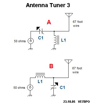
Antenna Tuner 3
Published:2012/12/13 21:23:00 Author:muriel | Keyword: Antenna Tuner
View full Circuit Diagram | Comments | Reading(811)
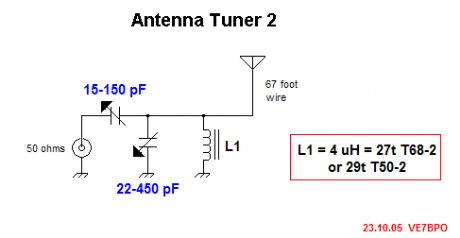
antenna tuner 2
Published:2012/12/13 21:12:00 Author:muriel | Keyword: antenna tuner
View full Circuit Diagram | Comments | Reading(1304)
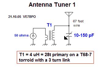
antenna tuner
Published:2012/12/13 21:11:00 Author:muriel | Keyword: antenna tuner
View full Circuit Diagram | Comments | Reading(2094)
favorite LED experiment
Published:2012/12/13 21:03:00 Author:muriel | Keyword: LED
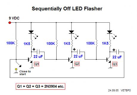
Sequentially Off LED Pulser
This circuit uses a series of transistors with an RC pair to pulse a string of LEDs.
This the favorite LED experiment I performed this summer. This flasher circuit is different in that it turns off alternate LEDs for about 1 second in sequence. When you connect this circuit to the 9 volt battery, all of the transistors are usually placed in saturation and therefore all the LEDs are on. Closing the switch on the base terminal of Q1 for a moment initiates the correct pulse sequence. The pulse initiates in Q1 which turns off the LED connected to the Q1 collector for about 1 second. When Q1 turns back on (goes into saturation), Q2 turns off. When Q2 turns back on then Q3 turns off and so on. The circuit is a closed loop and many more stages may be added.
You can experiment with different base resistor and coupling capacitor values to vary the speed of the LED string or to create a sense of randomness by varying each transistor's RC stage separately. This is a fun circuit! (View)
View full Circuit Diagram | Comments | Reading(3226)
6 LED FLASHER
Published:2012/12/13 21:02:00 Author:muriel | Keyword: 6 LED, FLASHER
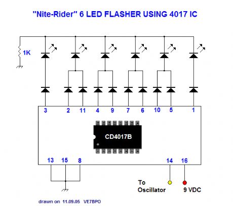
A schematic to allow the 4017 decade counter to sequentially flash 6 LEDS left-right-left-right-etc. Connect your favorite square wave oscillator to pin 14. I built 4 of these using various oscillators and LED colors. You might consider using lower DC voltages and if so, may adjust the 1K current limiting resistor by using ohm's law. The 10 small signal diodes may be any appropriate type including the 1N914 or 1N4148. None of my 4 projects exceeded 6 mA peak current draw, so battery life is excellent. I increased the 1K resistor to 1K5 in my 4th project as I found the LED's that I used too bright. (View)
View full Circuit Diagram | Comments | Reading(2782)
| Pages:242/2234 At 20241242243244245246247248249250251252253254255256257258259260Under 20 |
Circuit Categories
power supply circuit
Amplifier Circuit
Basic Circuit
LED and Light Circuit
Sensor Circuit
Signal Processing
Electrical Equipment Circuit
Control Circuit
Remote Control Circuit
A/D-D/A Converter Circuit
Audio Circuit
Measuring and Test Circuit
Communication Circuit
Computer-Related Circuit
555 Circuit
Automotive Circuit
Repairing Circuit