
Circuit Diagram
Index 256
Square Wave Oscillator
Published:2012/12/3 20:37:00 Author:muriel | Keyword: Square Wave Oscillator
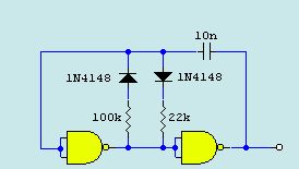
A very basic square wave generator using a CMOS 4011 NAND gate. (View)
View full Circuit Diagram | Comments | Reading(4299)
EMF Probe with Meter
Published:2012/12/3 20:36:00 Author:muriel | Keyword: EMF Probe , Meter
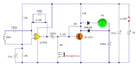
An electromagnetic field probe designed to detect changing electric and magnetic fields. The probe has a meter output and headphone socket as well. (View)
View full Circuit Diagram | Comments | Reading(1893)
Infra Red Remote Control Tester
Published:2012/12/3 20:36:00 Author:muriel | Keyword: Infra Red, Remote Control, Tester

A simple IR receiver to facilitate in testing of Infra Red Remote Control handsets. (View)
View full Circuit Diagram | Comments | Reading(1244)
Zener Diode Tester
Published:2012/12/3 20:35:00 Author:muriel | Keyword: Zener Diode, Tester
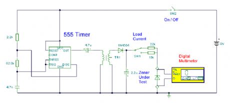
I have teamed up with Magazine Mikro Elektronica for this project. Please visit their site. I am very grateful to Aleksandar Dakic for the kind translation into Serbian and Romanian languages. (View)
View full Circuit Diagram | Comments | Reading(1591)
Electronic Mouse Trap
Published:2012/12/3 20:34:00 Author:muriel | Keyword: Electronic Mouse Trap

This circuit uses a conventional spring loaded mouse trap, available from hardware stores. However when a mouse is caught, the circuit triggers and transmits an interrupted tone on the commercial FM band to a nearby radio receiver. The transmitter and tone are adjustable so it is possible to build more than one unit and monitor several mouse traps simultaneously. (View)
View full Circuit Diagram | Comments | Reading(2279)
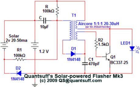
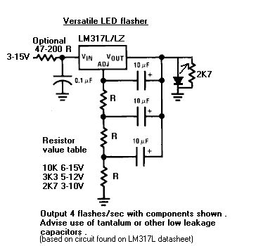
Solar Flasher
Published:2012/12/3 20:33:00 Author:muriel | Keyword: Solar Flasher
View full Circuit Diagram | Comments | Reading(1334)
Three Doorbells For The Hearing Impaired
Published:2012/12/3 20:33:00 Author:muriel | Keyword: Three Doorbells, Hearing Impaired
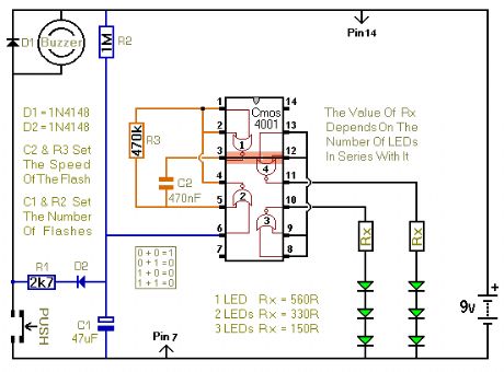
When the push switch is operated - the buzzer will sound and the LEDs will begin to flash. For the hearing members of the household - the buzzer acts as a regular doorbell. It also re-assures the visitor that the doorbell is working. When the push switch is released the buzzer will stop - but the LEDs will continue to flash. The length of time they will go on flashing is set by the values of R2 & C1. With the values shown in the diagram - the LEDs will flash for a further 30 seconds or so. If you make R2 a variable resistor, you can adjust the time period. If you want longer than 30 seconds - increase the value of C1 or R2. (View)
View full Circuit Diagram | Comments | Reading(809)
Room Monitor
Published:2012/12/3 20:32:00 Author:muriel | Keyword: Room Monitor
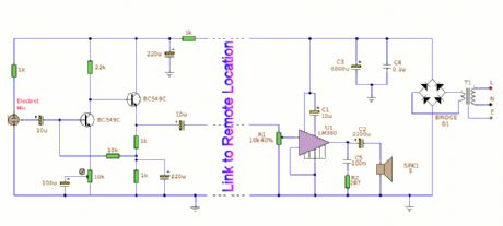
This circuit allows audio monitoring of a remote location and so doubles as a room monitor or baby alarm. It can be run from a 12 Volt battery or mains power supply as shown below. Interconnect uses 3 wires, so multi core cable can be used; alarm or telephone cable is suitable just leave any extra wires free. (View)
View full Circuit Diagram | Comments | Reading(0)
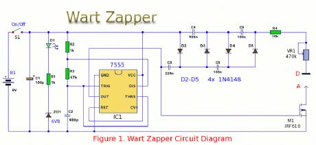
Wart Zapper
Published:2012/12/3 20:31:00 Author:muriel | Keyword: Wart Zapper
View full Circuit Diagram | Comments | Reading(3798)
LED Flasher 2
Published:2012/12/3 20:30:00 Author:muriel | Keyword: LED Flasher
View full Circuit Diagram | Comments | Reading(1908)
Ignition Coil Driver
Published:2012/12/3 20:30:00 Author:muriel | Keyword: Ignition Coil Driver

This design uses a 555 timer and three 2n3055 switching transistors to provide a variable frequency, variable voltage input to an automotive ignition coil. Normal output is 25kV when run at 12v input and at the coil's resonant frequency (8kHz). Increasing the voltage output to about 50kV is possible if the input voltage is increased to 34v, however this risks burning out the switching transistors when the system is operated for an extended time.
Electrical Diagram:
Capacitors: rated at 50v
Resistors: 1/2w, 5% tolerance
Output frequency to the coil is controlled by VR1, output voltage is controlled by VR2.
V+ is connected to pin 3 on the 5v regulator. (View)
View full Circuit Diagram | Comments | Reading(6377)
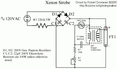
Xenon Strobe
Published:2012/12/3 20:28:00 Author:muriel | Keyword: Xenon Strobe
View full Circuit Diagram | Comments | Reading(0)
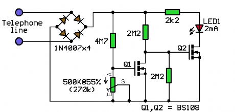
Privacy Circuit
Published:2012/12/3 20:28:00 Author:muriel | Keyword: Privacy Circuit
View full Circuit Diagram | Comments | Reading(659)
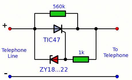
Telephone In-Use Indicator 2
Published:2012/12/3 20:27:00 Author:muriel | Keyword: Telephone In-Use Indicator
View full Circuit Diagram | Comments | Reading(1172)
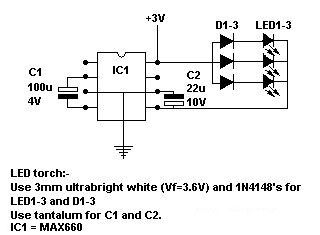
LED Torch 2
Published:2012/12/3 20:26:00 Author:muriel | Keyword: LED Torch
View full Circuit Diagram | Comments | Reading(1568)
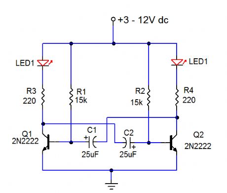
LED Flasher
Published:2012/12/3 20:26:00 Author:muriel | Keyword: LED Flasher
View full Circuit Diagram | Comments | Reading(0)
Monitor Splitter
Published:2012/12/3 20:24:00 Author:muriel | Keyword: Monitor Splitter

View full Circuit Diagram | Comments | Reading(745)
IR Remote Volume Controller
Published:2012/12/3 20:23:00 Author:muriel | Keyword: IR , Remote Volume, Controller
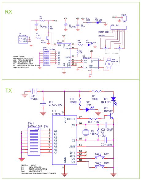
View full Circuit Diagram | Comments | Reading(1000)
Audio Indicator
Published:2012/12/3 20:22:00 Author:muriel | Keyword: Audio Indicator
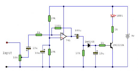
This circuit can be used to remotely monitor a loudspeaker, alarm, or audio source for presence of an audio waveform. It can also be directly connected across loudspeaker terminals used as a peak indicator. (View)
View full Circuit Diagram | Comments | Reading(792)
Decimal to BCD Convetor
Published:2012/12/3 20:20:00 Author:muriel | Keyword: Decimal to BCD Convetor
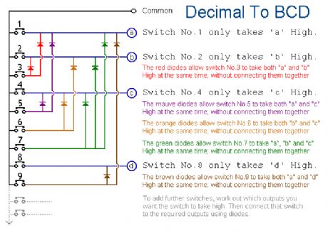

View full Circuit Diagram | Comments | Reading(875)
| Pages:256/2234 At 20241242243244245246247248249250251252253254255256257258259260Under 20 |
Circuit Categories
power supply circuit
Amplifier Circuit
Basic Circuit
LED and Light Circuit
Sensor Circuit
Signal Processing
Electrical Equipment Circuit
Control Circuit
Remote Control Circuit
A/D-D/A Converter Circuit
Audio Circuit
Measuring and Test Circuit
Communication Circuit
Computer-Related Circuit
555 Circuit
Automotive Circuit
Repairing Circuit