
Circuit Diagram
Index 253
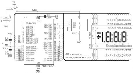
LCD thermometer
Published:2012/12/6 1:13:00 Author:muriel | Keyword: LCD thermometer
View full Circuit Diagram | Comments | Reading(1727)
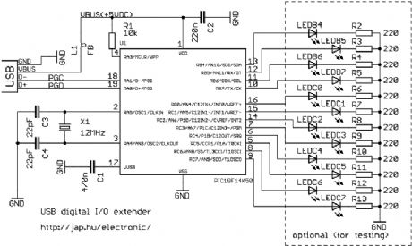
USB digital I/O extender
Published:2012/12/6 1:13:00 Author:muriel | Keyword: USB , digital I/O extender
View full Circuit Diagram | Comments | Reading(1527)
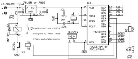
Electronic combination lock
Published:2012/12/6 1:12:00 Author:muriel | Keyword: Electronic combination lock
View full Circuit Diagram | Comments | Reading(0)
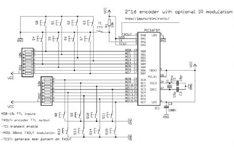
2^12 encoder
Published:2012/12/6 1:11:00 Author:muriel | Keyword: 2^12 encoder
View full Circuit Diagram | Comments | Reading(1104)
Learning IR remote control receiver
Published:2012/12/6 1:10:00 Author:muriel | Keyword: Learning IR , remote control , receiver
View full Circuit Diagram | Comments | Reading(1276)
Amplifier circuit for low frequency measurement
Published:2012/12/5 21:22:00 Author:Ecco | Keyword: Amplifier, low frequency measurement
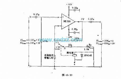
In order to accurately measure small amplitude AC voltage, the measuring circuit with operational amplifier is used. Operational amplifier NE530 can be used, the measurement frequency is more than 200kHz, so it can be used in the low frequency region. Measurement noise voltage can be ignored because it only has a few microvolts. Amplification factor 1 or 10 can be converted by the switch S on negative feedback branch circuit. When the amplification factor is 10, the amplification can be adjusted by potentiometer Rp. For example, if the input voltage is 100mV, you can adjust the output voltage to 1V.
(View)
View full Circuit Diagram | Comments | Reading(2383)
Unijunction transistor working performance speed measurement circuit
Published:2012/12/5 21:30:00 Author:Ecco | Keyword: Unijunction transistor, working performance , speed measurement
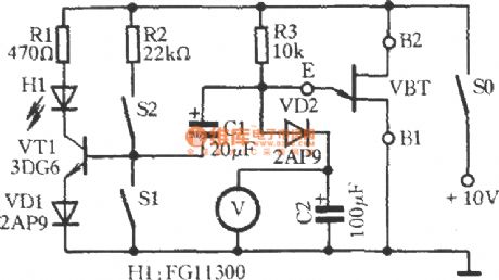
Measured single-junction transistor VBT ( set: BT33) and R3, C2 form relaxation oscillator. When VBT gets conduction, transistor VT1 obtains bias current by the bias resistor R2 ( S1 is OFF, S2 is closed), the light - emitting diode H1 emits light. +10 V power supply charges for C2 by R3 and VD2. The voltmeter V measured voltage across C2 will rise over time, when the E terminal potential reaches peak voltage of VBT, the VBT's E to B1 will be automatically turned on.
(View)
View full Circuit Diagram | Comments | Reading(1372)
Discriminant analysis methods for high - voltage capacitor
Published:2012/12/5 21:33:00 Author:Ecco | Keyword: Discriminant analysis methods, high - voltage capacitor
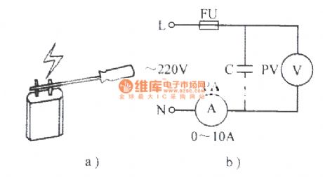
As shown in Figure a), touching the capacitor lead end, if there is a strong spark generated, this capacitor is good; if there is no spark, this capacitor has been damaged or a minimum capacity. Figure b) is used to test the capacity of the capacitor. Read out the reading on the two tables of PA, PB, the capacitor capacitance can be obtained according to the following formula. C = 3180 * Ic / Uc, C (μF ) , Ic (A ) , UC ( V ).
(View)
View full Circuit Diagram | Comments | Reading(711)
Simple phase sequence indicator
Published:2012/12/5 21:36:00 Author:Ecco | Keyword: Simple , phase sequence, indicator

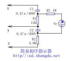
As shown in figure, as long as the X, Y, Z three lines are connected to three - phase circuit, the phase sequence of three - phase alternating current can be easily seen by the quenching of the neon tube light. If neon tube is lit , X , Y , and Z are respectively connected to A, C, B power supply phases. Conversely, if the neon tube is not lit, then the X , Y, and Z are connected to power supply A , B, and C phases. 1/8W carbon film resistors can be used, and the capacitor requires that the pressure to be greater than 400V. Neon can use neon fluorescent starter.
(View)
View full Circuit Diagram | Comments | Reading(4523)
HA-5320 noninverting unit gain mode basic connection circuit
Published:2012/12/5 20:30:00 Author:Ecco | Keyword: noninverting unit, gain mode, basic connection
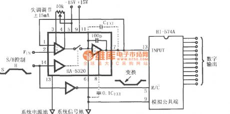
HA-5320 is used as a fast data acquisition A / D converting input stage, the input signal VIN is applied to pin 2 of HA-5320, after being sampling and holding amplified, it is sent to HI574A for analog - digital conversion, then it is converted to 12-bit digital signal output. S non / H signal can control the internal switch's turning on or off, i.e. sampling or holding state. If it needs to extend the hold time, it can be added the external keeping capacitor CEXT.
(View)
View full Circuit Diagram | Comments | Reading(821)
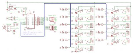
4/8-channel V4.2 infrared receiver
Published:2012/12/5 0:15:00 Author:muriel | Keyword: 4/8-channel, V4.2 , infrared receiver
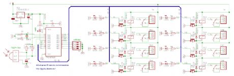
The difference between the 4-channel and the 8-channel version is only the software inside. The 8-channel receiver outputs are individually configurable for latched or momentary output. The 4-channel receiver has two outputs per channel: K1-K4 are latched outputs, K5-K8 are momentary outputs for the four channels. The valid LED shows the transmitter activity. Make sure to turn on all address jumpers when the transmitter diodes are absent, or the J1-J4 jumpers are cut. Choose V+ supply voltage between +6-15VDC, based on the relay voltage ratings. For 6V relays, use +6VDC, for 12V relays use +12VDC. (View)
View full Circuit Diagram | Comments | Reading(1112)
4/8-channel V4.2 radio receiver
Published:2012/12/5 0:14:00 Author:muriel | Keyword: 4/8-channel, V4.2, radio receiver
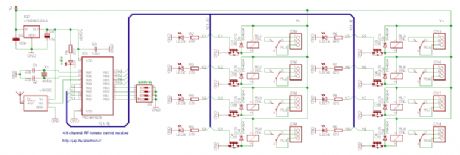
The difference between the 4-channel and the 8-channel version is only the software inside. The 8-channel receiver outputs are individually configurable for latched or momentary output. The 4-channel receiver has two outputs per channel: K1-K4 are latched outputs, K5-K8 are momentary outputs for the four channels. The valid LED shows the transmitter activity. Make sure to turn on all address switches when the transmitter diodes are absent, or the J1-J4 jumpers are cut. Choose V+ supply voltage between +6-15VDC, based on the relay voltage ratings. For 6V relays, use +6VDC, for 12V relays use +12VDC. (View)
View full Circuit Diagram | Comments | Reading(1282)
4/8-channel V4.2 infrared transmitter
Published:2012/12/5 0:12:00 Author:muriel | Keyword: 4/8-channel, V4.2, infrared transmitter
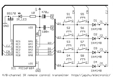
The difference between the 4-channel and the 8-channel version is only the software inside. The 8-channel transmitter has one button (S1-S8) per channel. The 4-channel transmitter uses S1-S4 buttons to turn on, S5-S8 buttons to turn off channel 1-4 (use with latched outputs on the receiver). The D1-D4 diodes and J1-J4 jumpers are optional, and are used to setup the transmitter address. V+ supply voltage should be between 2.5-5.5VDC. It is practical to use two or three AAA batteries. (View)
View full Circuit Diagram | Comments | Reading(696)
4/8-channel V4.2 radio transmitter
Published:2012/12/5 0:11:00 Author:muriel | Keyword: 4/8-channel, V4.2 , radio transmitter
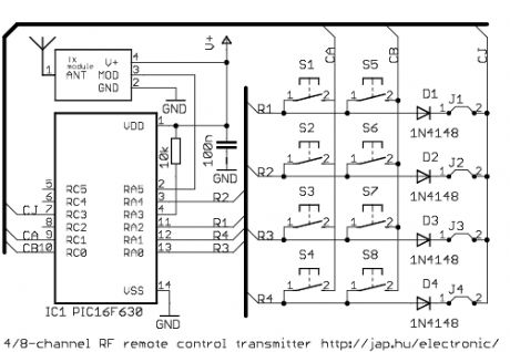
The difference between the 4-channel and the 8-channel version is only the software inside. The 8-channel transmitter has one button (S1-S8) per channel. The 4-channel transmitter uses S1-S4 buttons to turn on, S5-S8 buttons to turn off channel 1-4 (use with latched outputs on the receiver). The D1-D4 diodes and J1-J4 jumpers are optional, and are used to setup the transmitter address. Higher supply voltage resultshighertransmit power, but V+ range is 2-5.5VDC for the PIC MCU. When V+ is higher than 5VDC, use separate power for the mcu. (View)
View full Circuit Diagram | Comments | Reading(1003)
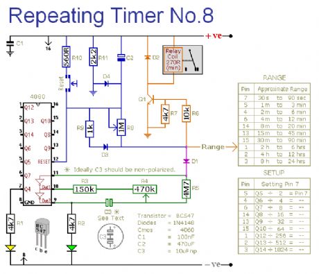
Repeating Timer No.8
Published:2012/12/5 0:09:00 Author:muriel | Keyword: Repeating Timer
View full Circuit Diagram | Comments | Reading(1080)
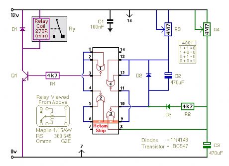
Repeating Timer No.7
Published:2012/12/5 0:09:00 Author:muriel | Keyword: Repeating Timer
View full Circuit Diagram | Comments | Reading(954)
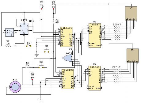
24 Second Shot Clock Mk 2
Published:2012/12/5 0:08:00 Author:muriel | Keyword: 24 Second, Shot Clock Mk
View full Circuit Diagram | Comments | Reading(1976)
741 Astable Timer
Published:2012/12/5 0:07:00 Author:muriel | Keyword: 741 Astable Timer
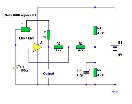
An astable timing circuit made from the ubiquitous 741 op-amp. (View)
View full Circuit Diagram | Comments | Reading(1160)
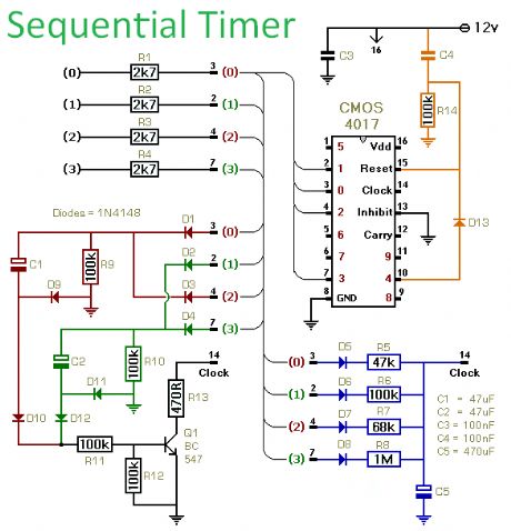
Sequential Timer
Published:2012/12/5 0:06:00 Author:muriel | Keyword: Sequential Timer
View full Circuit Diagram | Comments | Reading(2534)
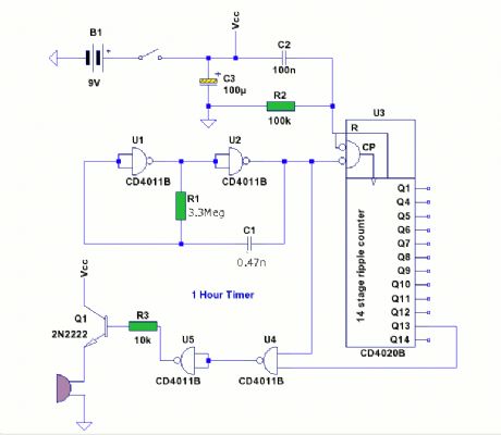
1 Hour Timer
Published:2012/12/5 0:06:00 Author:muriel | Keyword: 1 Hour, Timer
View full Circuit Diagram | Comments | Reading(911)
| Pages:253/2234 At 20241242243244245246247248249250251252253254255256257258259260Under 20 |
Circuit Categories
power supply circuit
Amplifier Circuit
Basic Circuit
LED and Light Circuit
Sensor Circuit
Signal Processing
Electrical Equipment Circuit
Control Circuit
Remote Control Circuit
A/D-D/A Converter Circuit
Audio Circuit
Measuring and Test Circuit
Communication Circuit
Computer-Related Circuit
555 Circuit
Automotive Circuit
Repairing Circuit