
Circuit Diagram
Index 259
Temperature measuring circuit with 5 channel low power programmable sensor signal processor AD7714 and Platinum thermal resistor Pt100 (PRTD)
Published:2012/11/29 0:55:00 Author:Ecco | Keyword: Temperature measuring, 5 channel , low power , programmable sensor , signal processor , Platinum , thermal resistor
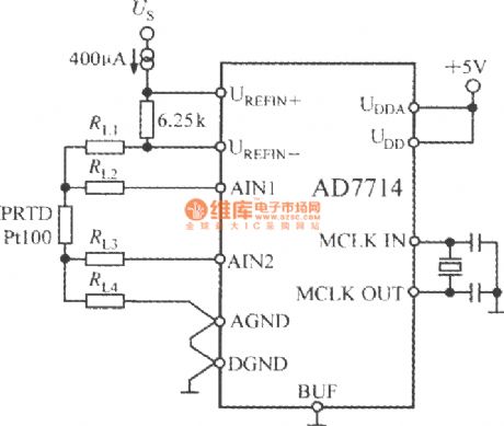
Pt100 uses 4-wire connection to eliminate pressure drop on lead resistors RL2 and RL3. External 400 μA current source provides excitation current for PT100, and then it will generate AD7714 voltage reference after passing 6.25kΩ resistor. Because the input voltage and reference voltage changes and the excitation current changes are proportional, the changes do not affect the measurement accuracy of the excitation current. But in order to avoid voltage reference from the effects of temperature changes, 6.25kΩ resistor should use metal film resistors with low temperature coefficient.
(View)
View full Circuit Diagram | Comments | Reading(3600)
High-accuracy pressure measurement system circuit diagram composed of intelligent dual-channel sensor signal processor MAX1463
Published:2012/11/29 0:50:00 Author:Ecco | Keyword: High-accuracy , pressure measurement system , intelligent , dual-channel sensor, signal processor
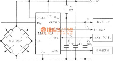
Bridge pressure sensor's output voltage is connected to the MAX1463 IN1+ IN1-side. Under CPU control, pressure signal is converted by nonlinear calibration, temperature compensation and ADC conversion, then it is sent to 80C51 MCU after being output from the serial interface; DAC also can convert it to the analog output voltage Uo, then it is sent to a digital voltmeter to show the measured pressure value. GPI01 universal digital I/O interface pin is connected to failure alarm, and the leader of sensor is open or CPU occurs overflowing, it can drive the buzzer alarm to emit sounds.
(View)
View full Circuit Diagram | Comments | Reading(2322)
Pressure detection system with MAX1460 intelligent sensor signal processor and Silicon pressure sensor
Published:2012/11/29 0:41:00 Author:Ecco | Keyword: Pressure detection system , intelligent sensor , signal processor, Silicon pressure sensor
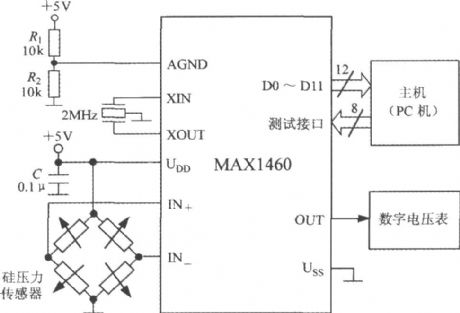
The system uses +5V power supply, and crystal oscillator frequency is 2MHz. R1 and R2 form a power divider, analog end (AGND) is connected to the mid-point of power supply. C is the power supply decoupling capacitor. Host can use PC, and MAX1460 is firstly tested by the host, then it receives the 12-bit parallel data output by MAX1460, and the test system is removed, MAX1460 and the testing sensor form a high precision intelligent pressure detection system, the conversion rate is 15 times/second, measuring error is less than ± 0. 1%.
(View)
View full Circuit Diagram | Comments | Reading(1304)
The voltage DAC0800 conversion circuit from current output D/A
Published:2012/11/29 0:28:00 Author:Ecco | Keyword: voltage, conversion , current output D/A
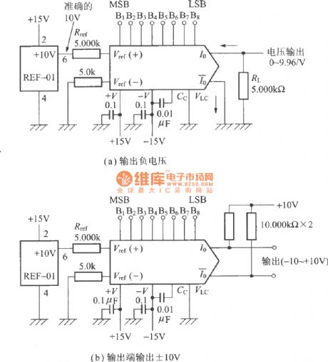
Figure a outputs negative voltage; The output end ofthe circuit shown inFigure b outputs ±10V.
(View)
View full Circuit Diagram | Comments | Reading(3003)
Light transformer checking current relay circuit
Published:2012/11/29 0:24:00 Author:Ecco | Keyword: Light transformer , checking , current relay
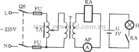
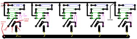
Lamp transformer usually uses 220/12/24/36 V power supply, and its capacity is 0.5kVA, it is mainly used for temporary lighting (low-voltage lamps). The current relay checking circuit is shown in the figure. According to relevant regulations, quick-break protection in power systems and overcurrent protection in the current relay should be checked on a regular basis once each year. According to the connection shown in above circuit, closing the knife switch QS, slowly adjusting the regulator TA, then the ammeter readings will be gradually increased to the AP KA dial number of current relay.
(View)
View full Circuit Diagram | Comments | Reading(1216)
Input protection circuit of broadband strain signal conditioner 1B31
Published:2012/11/23 2:56:00 Author:Ecco | Keyword: Input protection , broadband strain , signal conditioner
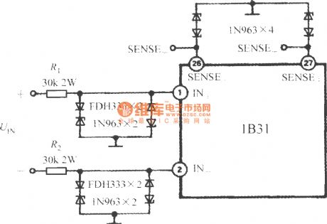
In the industrial field measurements, the 1B31 is needed to be designed input protection circuit to protect input end from instantaneous short-circuit and damage caused by 220V AC power accident. Input protection circuit is shown in the figure. It selects FDH333 diode with high conductivity and low leakage current, and 1N963 voltage regulator tube forms bi-directional parallel input limiting circuit, the input voltage can be clamped to a ± 12. 5V range. FDH333 average rectifier current is 200mA, reverse voltage is 125V, reverse-leakage current is only 1nA, maximum pressure drop can be up to 1. 0V, junction Capacitance is 6. 0pF.
(View)
View full Circuit Diagram | Comments | Reading(795)
Digital high accuracy pressure tester circuit (high-precision integrated pressure signal conditioner MAX1457)
Published:2012/11/23 2:52:00 Author:Ecco | Keyword: Digital, high accuracy , pressure tester , high-precision, integrated, pressure signal conditioner
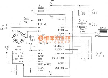
MAX1457 selects 93C66 4096b external read-only memory E2PROM. MCS-end is pulled into a high level after geting power, and it selects the main chip. +5V power supplyprovides partial pressurefor the bias circuit by the resistor RBIAS (400k). C2, C4 and C6 are the decoupling capacitors. C1, C3, C5, C7~C11are bypass capacitors. When you take RISRC=50k Ω, excitation current is 0. 5mA.
(View)
View full Circuit Diagram | Comments | Reading(1575)
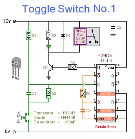
Toggle Switch No. 1
Published:2012/11/29 0:43:00 Author:muriel | Keyword: Toggle Switch
View full Circuit Diagram | Comments | Reading(866)
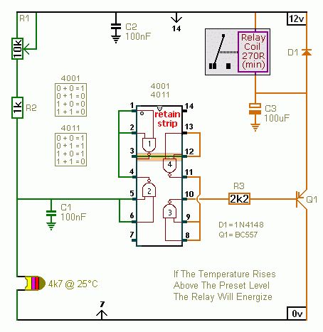
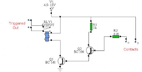
Temperature Controlled Relays
Published:2012/11/29 0:42:00 Author:muriel | Keyword: Temperature Controlled Relays
View full Circuit Diagram | Comments | Reading(923)
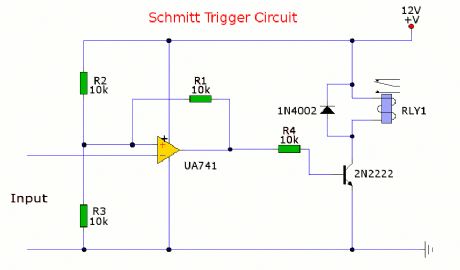
Schmitt Trigger
Published:2012/11/29 0:41:00 Author:muriel | Keyword: Schmitt Trigger

View full Circuit Diagram | Comments | Reading(0)
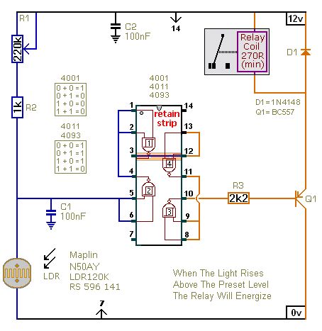
Light Controlled Relays
Published:2012/11/29 0:40:00 Author:muriel | Keyword: Light Controlled, Relays


View full Circuit Diagram | Comments | Reading(827)
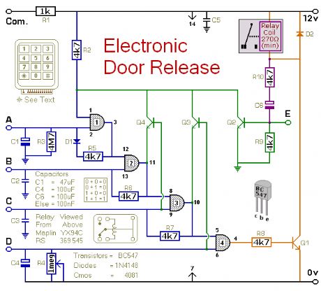
Electronic Door Release 2
Published:2012/11/29 0:39:00 Author:muriel | Keyword: Electronic Door Release
View full Circuit Diagram | Comments | Reading(745)
Keypad Switch No. 2
Published:2012/11/29 0:37:00 Author:muriel | Keyword: Keypad Switch

View full Circuit Diagram | Comments | Reading(791)
4 Digit Keypad Switch
Published:2012/11/29 0:37:00 Author:muriel | Keyword: 4 Digit Keypad, switch
View full Circuit Diagram | Comments | Reading(872)
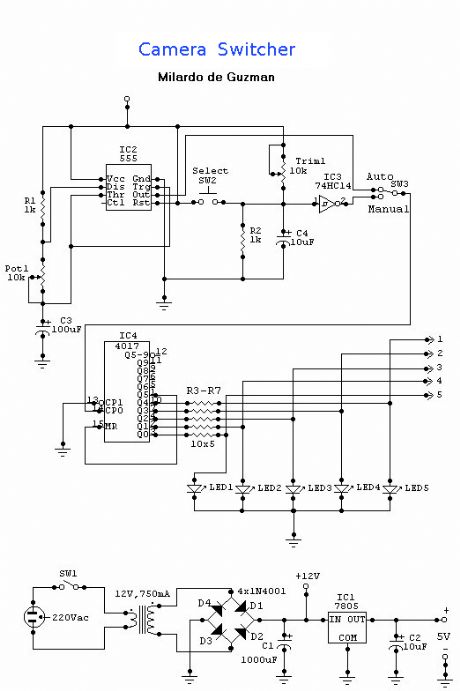
Camera Switcher
Published:2012/11/29 0:36:00 Author:muriel | Keyword: Camera Switcher

View full Circuit Diagram | Comments | Reading(963)
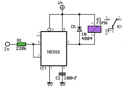
VCS using 555 Timer
Published:2012/11/29 0:35:00 Author:muriel | Keyword: VCS using 555 Timer

View full Circuit Diagram | Comments | Reading(2800)
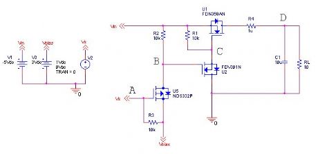
Negative Voltage Load Switch
Published:2012/11/29 0:34:00 Author:muriel | Keyword: Negative Voltage, Load Switch
View full Circuit Diagram | Comments | Reading(1707)
Triac Based Light Controller
Published:2012/11/29 0:34:00 Author:muriel | Keyword: Triac Based , Light Controller
View full Circuit Diagram | Comments | Reading(1199)
Water Activated Relay
Published:2012/11/29 0:33:00 Author:muriel | Keyword: Water Activated Relay
View full Circuit Diagram | Comments | Reading(938)
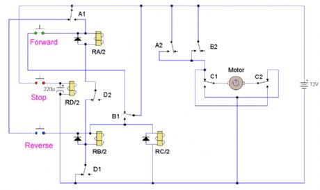
Motor Reversing Circuit
Published:2012/11/29 0:33:00 Author:muriel | Keyword: Motor Reversing Circuit
View full Circuit Diagram | Comments | Reading(769)
| Pages:259/2234 At 20241242243244245246247248249250251252253254255256257258259260Under 20 |
Circuit Categories
power supply circuit
Amplifier Circuit
Basic Circuit
LED and Light Circuit
Sensor Circuit
Signal Processing
Electrical Equipment Circuit
Control Circuit
Remote Control Circuit
A/D-D/A Converter Circuit
Audio Circuit
Measuring and Test Circuit
Communication Circuit
Computer-Related Circuit
555 Circuit
Automotive Circuit
Repairing Circuit