
Circuit Diagram
Index 255
△ connection motor zero sequence voltage relay phase failure protection circuit
Published:2012/12/4 20:47:00 Author:Ecco | Keyword: △ connection, motor, zero sequence, voltage relay, phase failure, protection
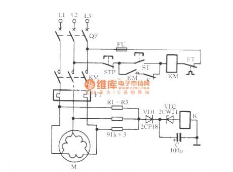
In the circuit shown in figure, three resistors R1 ~ R3 are connected as an artificial neutral point, when the motor is off-phase, the neutral point shifts, relay K is energized, the normally closed contact gets action to cut KM coil loop, KM loses power and releases, thereby protecting the motor.
(View)
View full Circuit Diagram | Comments | Reading(2946)
Six-way blinking light string circuit ( 1 ) ( HFC3018 )
Published:2012/12/4 20:55:00 Author:Ecco | Keyword: Six-way, blinking light string
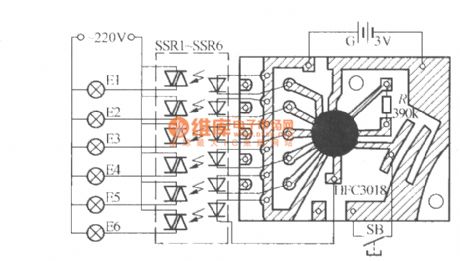
The circuit uses 5-way flash signal output by HFC3018 to drive solid state relays SSR1 ~ SSR5 and make them sequentially turn on and off, which enables the lantern strings E1 ~ E5 to be extinguished in a turn. Manifold output analog sound signal can drive solid state relay SSR6, which make the the six groups of lantern chain E6 flash with analog sound storaged in manifold, pressing the button switch SB one time can obtain a flashing mode. HFC3018 has eight kinds of analog sound, it can produce eight different flashing effects.
(View)
View full Circuit Diagram | Comments | Reading(1420)
Function generator circuit diagram with ICL8038
Published:2012/12/4 21:35:00 Author:Ecco | Keyword: Function generator
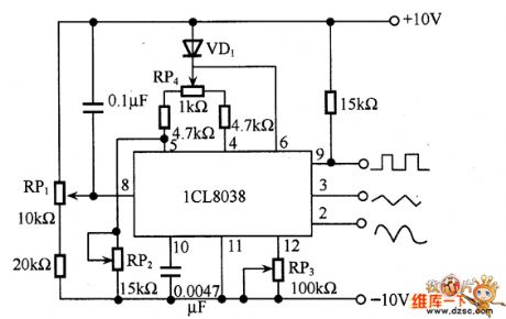
The circuit can get square wave, triangle wave and sine wave. And the triangular wave is directly formed by a capacitance constant current charging and discharging, the square wave is obtained by the control signal, and the sine wave is obtained by a triangular wave passing a fold line. Therefore, sine wave here is not a smooth curve, distortion is about t%, but it is sufficient for general use. As shown in figure, it uses ICL8038 function generator circuit. In the circuit, RP1 is used to adjust the frequency, it should use good quality potentiometer with adjustable frequency between 20Hz ~ 20kHz. The RP3 is used to adjust the degree of distortion, RP4 is used to adjust the duty cycle.
(View)
View full Circuit Diagram | Comments | Reading(14825)
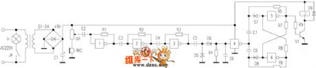
Easy making negative ion generator circuit
Published:2012/12/4 21:27:00 Author:Ecco | Keyword: Easy making, negative ion generator
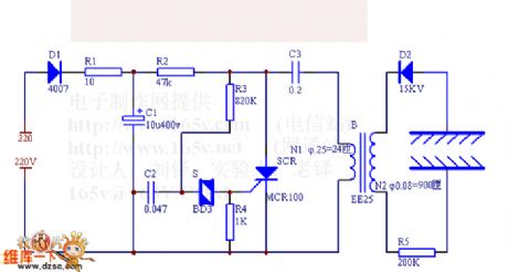
Simple negative ion generator can increase negative ions, which can help people with hypnotic, antiperspirant, analgesic, increase appetite functions, and it can eliminate fatigue.
220V AC mains is rectified by D1, then it charges for C3 and C2, when C2 is charged to the the neon bulb conduction to trigger SCR conduction, C3 discharges the SCR, B's L1 discharges, after B inductive boost, the 8kV DC high voltage reversed and rectified by D2 can make generator M molecular ionization to produce negative ions.
(View)
View full Circuit Diagram | Comments | Reading(7326)
Voice lamp circuit diagram
Published:2012/12/4 21:20:00 Author:Ecco | Keyword: Voice lamp
The circuit uses a six-gate IC CD4069, and its Gate 1, Gate 2, 3, and R1, R2, R3 form a three-level signal amplifier. Once people click on a Palm, applause is picked up by electret microphone MIC, and its sensitivity is adjusted by RP and amplified by subsequent three-level amplifier, then detected by C5, D5, D6, C6 to get DC control voltage, this voltage is inverted by gate 4 to control the flip of subsequent bistable circuit.
(View)
View full Circuit Diagram | Comments | Reading(1028)
Automatical opening and stopping control circuit of fish tank water pump
Published:2012/12/3 21:44:00 Author:Ecco | Keyword: Automatical opening , stopping control , fish tank , water pump
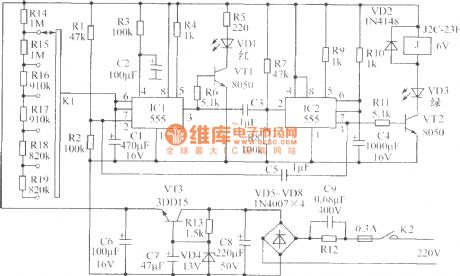
It uses two 555 -based circuits. Its peripheral circuits have a similar structure, and the closed loop is formed by cross- connected capacitors C5 , C3. The device running has two states: working state and intermittent state. In order to guarantee the device's working condition, R3 and C2 form a reset circuit on IC1's 4 feet. This circuit smallest intermittent is half of an hour, and the maximum intermittent is 3h. According tohe R10 values given in Figure, the pump working time is 25min ~ 30min.
(View)
View full Circuit Diagram | Comments | Reading(1515)
Temperature measuring circuit
Published:2012/12/3 21:38:00 Author:Ecco | Keyword: Temperature measuring
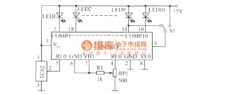
In the figure, S1 is the point / bar display mode changeover switch. When the power supply voltage Vcc> 8V, LED1 ~ LED10 don't need to use limiting resistor connected in series. When LED is lit, the cuttent is set by external resistor connected to pin 4,6, assuming pin 4,6 external resistor is 1.2kΩ ( inlcuding the resistance between the resistor R1, BP1 center head and pin 4), 10kΩ resistor is connected in parallel with the LM3914 internal divider, the equivalent resistance between pin 4 and pin 6 is about 10.7kΩ, the current of voltage divider circuit provided by 1.25V reference voltage is 1.25V/1.07kΩ ≈ 1.2mA.
(View)
View full Circuit Diagram | Comments | Reading(1181)
External audio spectrum monitor circuit diagram
Published:2012/12/3 21:25:00 Author:Ecco | Keyword: External, audio spectrum monitor
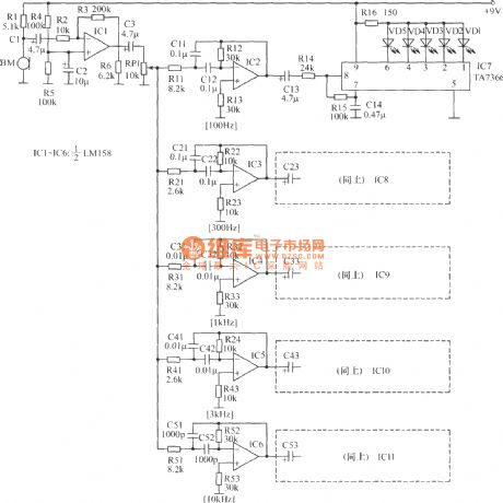
Generally top-grade audio equipment has audio spectrum display device which can not only help know instantaneously the playback signal spectrum, but also has the elegant and beautiful visual effects. This external audio spectrum display described here doesn't need any electrical stereo equipment, if irt is simply placed in the speaker front the voice box, it can visually dynamically show the frequency spectrum of the audio signal with nice and good looking. All the displays use integrated operational amplifiers and ASIC in design.
(View)
View full Circuit Diagram | Comments | Reading(1249)
The speed tester circuit for testing transistor quality
Published:2012/12/3 20:33:00 Author:Ecco | Keyword: speed tester, testing , transistor quality
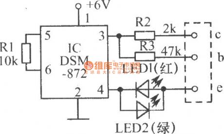
(1) The inserted NPN transistor is intact. IC's pin 3 is high, pin 4 is low, then the tested tube gets conduction, red light-emitting diode LED1 is light; when IC's pin 3 is low, pin 4 is high, then the tube is cut-off, LED1 and LED2 do not shine, the general view is twinkling light from LED1.
(View)
View full Circuit Diagram | Comments | Reading(1433)
Human reaction speed tester
Published:2012/12/3 21:13:00 Author:Ecco | Keyword: Human reaction , speed tester
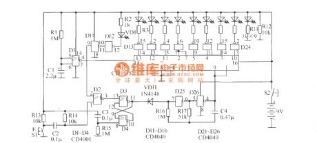
NAND gate D25, D26 form multivibrator which outputs the clock pulse with approximately 50ms cycle. IC1 can form an 8 - bit right shift register, and D1 forms a starting up delay circuit output, of which signal is used as its serial input data. When the machine starts, since D1 output is 1 , under the effect of clock pulses, IC1's all 8-bit Storage units quickly become 1 , after 3s ~~ 4s, D1 output becomes 0 , then tested light VD1 is lit.
(View)
View full Circuit Diagram | Comments | Reading(1772)
Beat Balance Metal Detector circuit
Published:2012/12/3 20:44:00 Author:muriel | Keyword: Beat Balance, Metal Detector circuit

View full Circuit Diagram | Comments | Reading(1933)
Signal Tracer and Injector
Published:2012/12/3 20:42:00 Author:muriel | Keyword: Signal Tracer, Injector
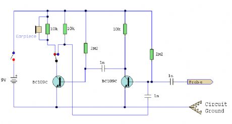
A simple test circuit to fault find audio and radio equipment. Can be used to inject a square wave signal, rich in harmonics, or used with headphones as an audio tracer.
(View)
View full Circuit Diagram | Comments | Reading(1227)
Bench Amplifier
Published:2012/12/3 20:42:00 Author:muriel | Keyword: Bench Amplifier
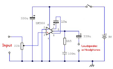
A small 325mW amplifier with a voltage gain of 200 that can be used as a bench amplifier, signal tracer or used to amplify the output from personal radios, etc. (View)
View full Circuit Diagram | Comments | Reading(744)
Two Simple Crystal Test Circuits
Published:2012/12/3 20:41:00 Author:muriel | Keyword: Two Simple Crystal, Test Circuits
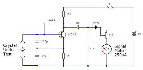
Two simple test circuits to check operation of quartz crystals. (View)
View full Circuit Diagram | Comments | Reading(1482)
Sine Wave Generator
Published:2012/12/3 20:40:00 Author:muriel | Keyword: Sine Wave Generator

A classic Wien Bridge oscillator using an Op-Amp covering a frequency range of 15 to 150kHz in four switched steps. (View)
View full Circuit Diagram | Comments | Reading(3052)
Connection Tester
Published:2012/12/3 20:40:00 Author:muriel | Keyword: Connection Tester

A low resistance ( 0.25 - 4 ohm) continuity tester for checking soldered joints and connections. (View)
View full Circuit Diagram | Comments | Reading(1243)
Multi Wire Cable Tester
Published:2012/12/3 20:39:00 Author:muriel | Keyword: Multi , Wire Cable Tester

A multi wire cable tester with a separate LED for each wire. Will show open circuits, short circuits, reversals, earth faults, continuity and all with four IC's. Designed initially for my intercom, but can be used with alarm wiring, CAT 5 cables and more. (View)
View full Circuit Diagram | Comments | Reading(2142)
Milligaus Meter
Published:2012/12/3 20:39:00 Author:muriel | Keyword: Milligaus Meter
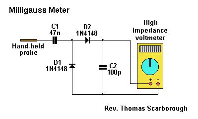
The circuit of Fig.1 provides an easy yet reliable way to detect the intensity of a.c. (or e.l.f.) fields around the home or workplace. It is doubly effective because it does not merely detect the electromagnetic radiation emitted by electrical appliances, but the electromagnetic energy actually absorbed by the body. (View)
View full Circuit Diagram | Comments | Reading(1293)
Function Generator
Published:2012/12/3 20:38:00 Author:muriel | Keyword: Function Generator
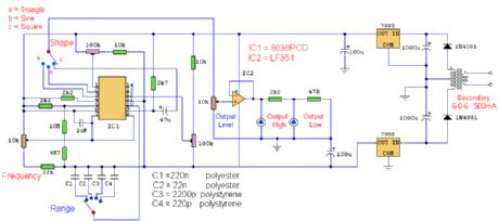
A function generator using the ICL8038 integrated circuit. Is has four ranges and capable of sine, square and triangle outputs. (View)
View full Circuit Diagram | Comments | Reading(0)
Logic Probe
Published:2012/12/3 20:38:00 Author:muriel | Keyword: Logic Probe
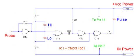
This logic probe uses a single CMOS 4001 IC and can display high, low and pulsing outputs. (View)
View full Circuit Diagram | Comments | Reading(0)
| Pages:255/2234 At 20241242243244245246247248249250251252253254255256257258259260Under 20 |
Circuit Categories
power supply circuit
Amplifier Circuit
Basic Circuit
LED and Light Circuit
Sensor Circuit
Signal Processing
Electrical Equipment Circuit
Control Circuit
Remote Control Circuit
A/D-D/A Converter Circuit
Audio Circuit
Measuring and Test Circuit
Communication Circuit
Computer-Related Circuit
555 Circuit
Automotive Circuit
Repairing Circuit