
Circuit Diagram
Index 827
Unity_gain_voltage_follower_using_half_of_an_ECG947_dual_operational_amplifier
Published:2009/7/19 21:20:00 Author:Jessie
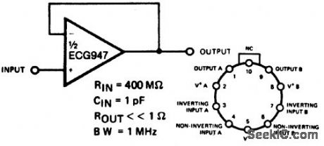
Unity-gain voltage follower using half of an ECG947 dual operational amplifier. The ECG947 is short-circuit protected and requires no external components for frequency compensation (courtesy GTE Sylvania Incorporated). (View)
View full Circuit Diagram | Comments | Reading(560)
±5_AND±12_V_FOR_COMPUTER
Published:2009/7/19 21:20:00 Author:Jessie
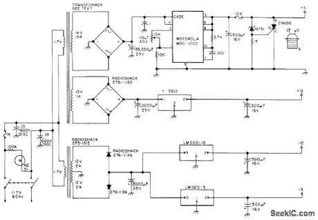
Provides all voltages required for 8080-4BD microcomputer system marketed by The Digital Group (Denver, CO). Transformer for positive supplies is 6.3-V 20-A unit with secondary replaced by two new windings giving required voltage and current. Crowbar circuit using 2N688 SCR protects ICs in memory and CPU. Use of at feast 50,000 μF in filter of 5-V supply prevents noise problems in computer MPC-1000 5-V 10-A regulator should be mounted on large heatsink at rear of computer housing in open air.- L.I. Hutton, A Ham's Computer, 73 Magazine, Dec. 1976, p78-79 and 82-83. (View)
View full Circuit Diagram | Comments | Reading(915)
SOUND_TRIGGERED_FLASH
Published:2009/7/10 3:49:00 Author:May
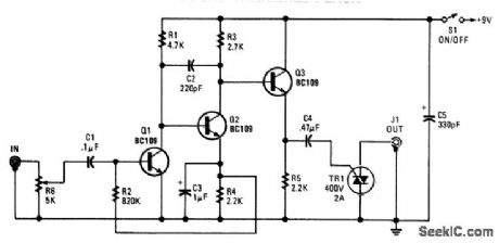
Audio input from a microphone drives amplifier Q1/Q2/Q3 to produce an ac voltage across R5. C4 couples this to TRI, causing it to conduct, triggering photoflash or other device that is connected to J1. (View)
View full Circuit Diagram | Comments | Reading(1338)
THERMAL_NUCLEAR_RADIATION_DETECTOR
Published:2009/7/19 21:19:00 Author:Jessie
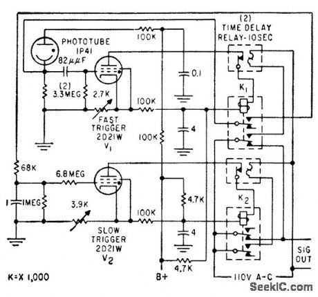
Triggers only on Light lash from nuclear explosion, consisting of initial fast-rising pulse lasting a few millisec, followed by pulse lasting over 1 sec. Discriminates against short lashes from lightning and shell bursts, and long slowly rising pulses caused by headlights and sunlight reflections.-J. C. Champeny, T. E. Petriken, and S. Siciliano, Nuclear Bomb Alarm Systems, Electronics, 32:19, p 53-55. (View)
View full Circuit Diagram | Comments | Reading(1476)
4_RANGE_ac_MILLIVOLTMETER
Published:2009/7/10 3:47:00 Author:May
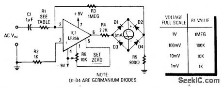
By placing the rectifter in the op amp feedback path, nonlinearity is greatly reduced to insigniftcant levels.The meter will read the full-wave rectifted average (absolute value) of the input signal.Frequency response is a few Hz to about 50 kHz. (View)
View full Circuit Diagram | Comments | Reading(1202)
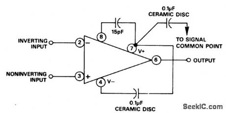
Voltage_follower_using_an_MC1539_op_amp_with_unity_gain_compensation
Published:2009/7/19 21:17:00 Author:Jessie
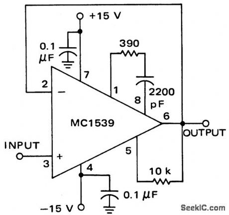
Voltage follower using an MC1539 op amp with unity-gain compensation (courtesy Motorola Semiconductor Products Inc.). (View)
View full Circuit Diagram | Comments | Reading(685)
Unity_gain_voltage_follower_using_an_ECG941_941D_941M_operational_amplifier
Published:2009/7/19 21:16:00 Author:Jessie
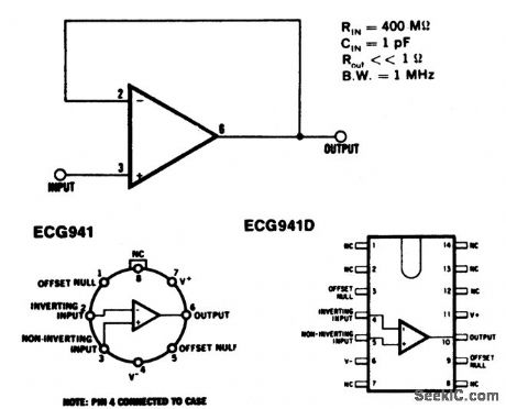
Unity-gain voltage follower using an ECG941/941D/941M operational amplifier. Typical supply voltage is ±1 5 volts(courtesy GTE Sylvania Incorporated). (View)
View full Circuit Diagram | Comments | Reading(708)
JUNCTION_DIODE_ALPHA_DETECTOR
Published:2009/7/19 21:15:00 Author:Jessie
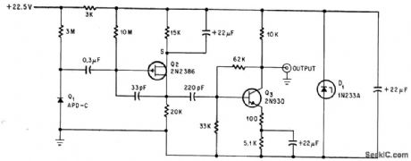
Used for counting alpha particles at high altitudes in dew-point hygrometer. Signal-to-noise ratio is poor (about 4 to 1).-C. R. Seashore and C. D, O'Brien, FET Detects Alpha Particles Better and More Precisely, Electronics, 38:3, p 64-66. (View)
View full Circuit Diagram | Comments | Reading(955)
SLIDE_PROJECTOR_AUTO_ADVANCE
Published:2009/7/10 3:47:00 Author:May
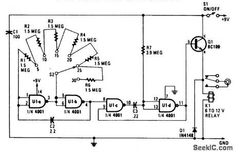
A 4001 CMOS Quad NORgate is set up as an astable multivibrator, which drives a simple differentia-tor and relay driver. Depending on the setting of S2, a delay of 5 to 30 seconds is generated. S2 and R1 through R6 can be replaced by a single 10-MΩ pot, if desired. (View)
View full Circuit Diagram | Comments | Reading(970)
Op_amp_with_minimum_settling_time_using_an_AD518_8_pin_TO99_
Published:2009/7/19 21:14:00 Author:Jessie


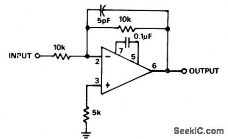
Op amp with minimum settling time using an AD518 8-pin TO99 (courtesy Analog Devices, Inc.). (View)
View full Circuit Diagram | Comments | Reading(809)
TRANSISTORIZED_GEIGER_COUNTER
Published:2009/7/19 21:14:00 Author:Jessie
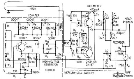
Rate-meter circuit converts output of halogen-type counter directly into meter indication corresponding to radiation intensity. Counter triggers two-transistor switch to place low-impedance load across conventional dual-output diode pump. Two halves of pump current are summed in metering circuit.-F. S. Goulding, Transistorized Geiger Counter Fits in Probe, Electronics, 32:3, p 64-66. (View)
View full Circuit Diagram | Comments | Reading(2182)
Low_drift_low_noise_amplifier_using_an_ECG941_941D_941M_operational_amplifier_and_a_μA727B_temperature_controlled_differential_amplifier
Published:2009/7/19 21:13:00 Author:Jessie
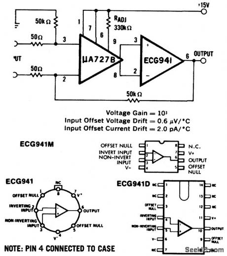
Low-drift low-noise amplifier using an ECG941/941D/941M operational amplifier and a μA727B temperature controlled differential amplifier. Typical supply voltage is ±15 volts (courtesy GTE Sylvania Incorporated). (View)
View full Circuit Diagram | Comments | Reading(502)
Unity_gain_op_amp_using_an_AD5098_pin_7099
Published:2009/7/19 21:12:00 Author:Jessie
Unity-gain op amp using an AD5098-pin 7099 (courtesy Analog Devices, Inc.). (View)
View full Circuit Diagram | Comments | Reading(573)
Noninverting_amplifier_using_an_EOG941_941_D_941_M_operational_amplifier
Published:2009/7/19 21:11:00 Author:Jessie
Noninverting amplifier using an ECG941/941D/941M operational amplifier. Typical supply voltage is ±15 volts (courtesy GTE Sylvania Incorporated). (View)
View full Circuit Diagram | Comments | Reading(686)
Op_amp_with_FET_AGC_circuit_
Published:2009/7/19 21:10:00 Author:Jessie
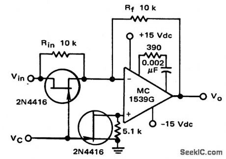
Op amp with FET AGC circuit (courtesy Motorola Semiconductor Products Inc.). (View)
View full Circuit Diagram | Comments | Reading(2270)
Simple_differentiator_using_an_ECG941_941D_941M_operational_amplifier
Published:2009/7/19 21:09:00 Author:Jessie
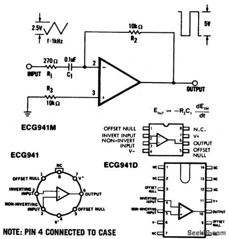
Simple differentiator using an ECG941/941D/941M operational amplifier. Typical supply voltage is ±15volts (courtesy GTE Sylvania Incorporated). (View)
View full Circuit Diagram | Comments | Reading(721)
GATED_CLAMP_FOR_PPI_SWEEP
Published:2009/7/19 21:09:00 Author:Jessie
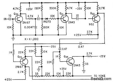
Uses monostable mvbr signal to generate reference level for yoke driven-C. E. Veazie, Transistorized Radar Sweep Circuits Using Low Power, Electronics, 32:26, p 46-47. (View)
View full Circuit Diagram | Comments | Reading(741)
0_TO_±15V_TRACKING_AT_100mA_OR_2A
Published:2009/7/19 21:09:00 Author:Jessie
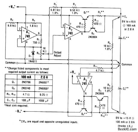
Basic tracking regulator is combined with transistors to extend output to voltages higher than zener reference and provide higher output currents. Choice of transistors for Q1 and Q2 determines maximum load current.-W. G. Jung, IC Op-Amp Cookbook, Howard W. Sams, indi-anapolis, IN, 1974, p 161-163. (View)
View full Circuit Diagram | Comments | Reading(838)
Feedforward_frequency_compensation_circuit_using_an_AD101A_201A_301A_op_amp
Published:2009/7/19 21:09:00 Author:Jessie
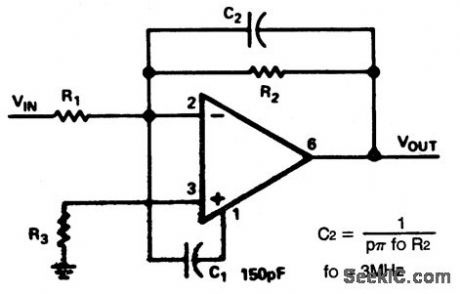
Feedforward frequency compensation circuit using an AD101A/201A/301A op amp. Typical supply voltage is ±15 volts (courtesy Analog Devices, Inc.). (View)
View full Circuit Diagram | Comments | Reading(966)
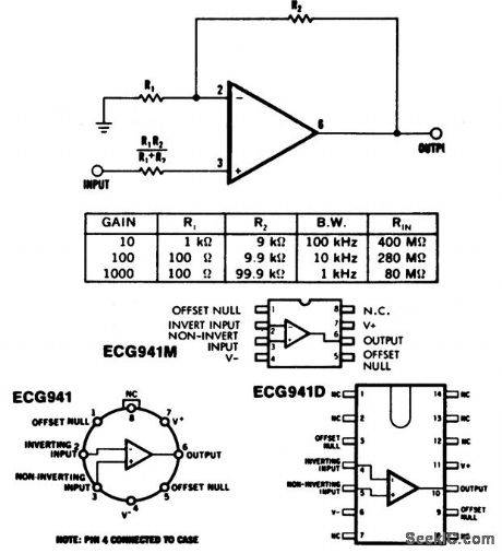
Inverting_amplifier_using_an_ECG941_941D_941M_operational_amplifier
Published:2009/7/19 21:08:00 Author:Jessie
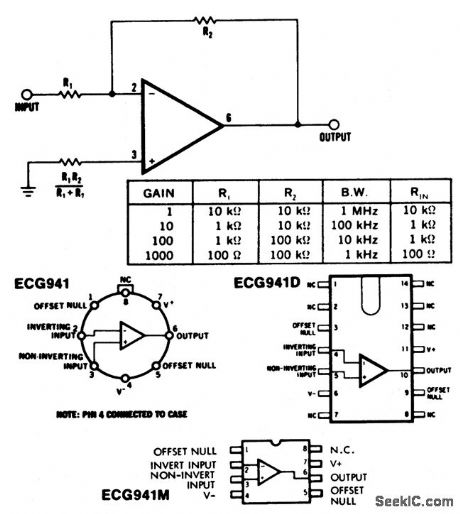
Inverting amplifier using an ECG941/941D/941M operational amplifier. Typical supply voltage is ±15 volts (courtesy GTE Sylvania Incorporated). (View)
View full Circuit Diagram | Comments | Reading(723)
| Pages:827/2234 At 20821822823824825826827828829830831832833834835836837838839840Under 20 |
Circuit Categories
power supply circuit
Amplifier Circuit
Basic Circuit
LED and Light Circuit
Sensor Circuit
Signal Processing
Electrical Equipment Circuit
Control Circuit
Remote Control Circuit
A/D-D/A Converter Circuit
Audio Circuit
Measuring and Test Circuit
Communication Circuit
Computer-Related Circuit
555 Circuit
Automotive Circuit
Repairing Circuit