
Circuit Diagram
Index 828
DISTANCE_MARK_GENERATOR_7
Published:2009/7/19 21:07:00 Author:Jessie
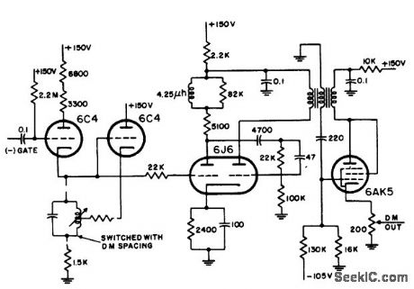
Uses switched Hartley oscillator, mvbr-type trigger shaper, and parallel-triggered blocking oscillator to generate distance marks for 2, 5, and 25 miles in airborne search radar. RLC unit is switched to change mark spacing.-NBS, Handbook Preferred Circuits Navy Aeronautical Electronic Equipment, Vol, 1, Electron Tube Circuits, 1963, p N8-2. (View)
View full Circuit Diagram | Comments | Reading(1509)
Differential_amplifier_using_an_MC1539_op_amp
Published:2009/7/19 21:07:00 Author:Jessie
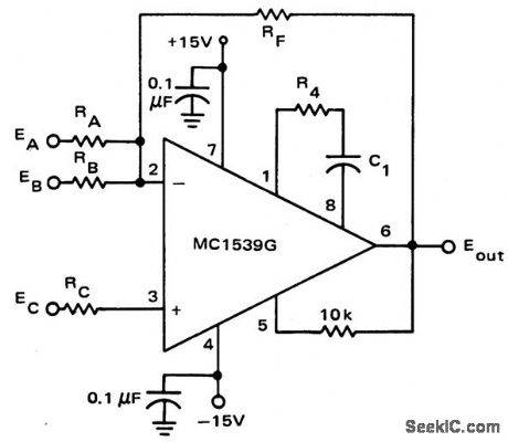
Differential amplifier using an MC1539 op amp (courtesy Motorola Semiconductor Products Inc.). (View)
View full Circuit Diagram | Comments | Reading(838)
Multimeter_single_chip
Published:2009/7/19 21:49:00 Author:Jessie
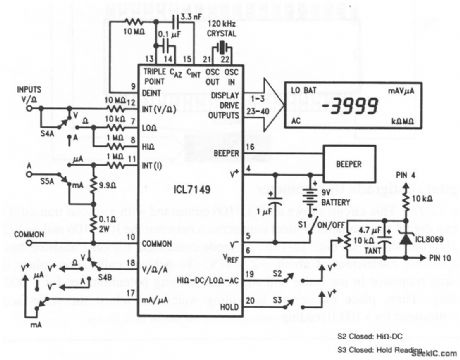
This circuit shows an ICL7149 that is connected as a low-power, autoranging digital multimeter. Although the ohms ranges do not need protection, the current ranges should be provided with fast-blow fuses between 55A and the 0.1- and 9.9-Ω shunt resistors. Also, the 10-kΩ resistor at pin 7 must be able to dissipate 1.2 or 4.8 W for short periods during accidental application of 110- or 220-V line voltages, respectively. The suggested crystal is a Statek CX-1V, the display is an LXD part number 38D8R02H, and the beeper is a muRata PKM24-4A0. (View)
View full Circuit Diagram | Comments | Reading(4289)
PREFERRED_SERIES_TRIGGERED_BLOCKING_OSCILLATOR
Published:2009/7/19 21:48:00 Author:Jessie
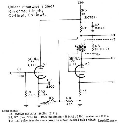
Responds to more slowly rising trigger than parallel-triggered version. Gathode follower V1 is included to provide required low driving impedance and minimize reaction of oscillator on trigger source. Designed for repetition rates up to 2,000 pps. Four terminals give choice of positive or negative output from positive input. Plate voltage is 300 V for 5814A and 150 V for 6111.-NBS, Handbook Preferred Circuits, Navy Aeronautical Electronic Equipment, Vol.I, Electron Tube Circuits, 1963, PC 49, p 49-2. (View)
View full Circuit Diagram | Comments | Reading(971)
COLD_CATHODE_COUNT_RATE_CIRCUIT
Published:2009/7/19 21:48:00 Author:Jessie

Fourelement cold-cathode tube operates directly from output pulse of 6292 photomultiplier receiving light output of Zns screen of alpha particle detector. Maximum counting rate is 100 counts per second.-M. H. Goosey, De-signing Cold-Cathode Tube Circuits, Electron-ics, 31:3, p 101-108. (View)
View full Circuit Diagram | Comments | Reading(651)
PREFERRED_DISTANCE_MARK_DIVIDER
Published:2009/7/19 21:46:00 Author:Jessie
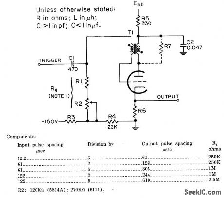
Used to generate distance marks when several must be displayed simultaneously. Maximum division factor is 5. For 5814A, R6 is 100 ohms and plate voltage is 300 V. For 6111, R6 is 150 ohms and plate voltage is 150 V. R7 should be maximum that will just suppress ringing.-NBS, Handbook Preferred Circuits Navy Aeronautical Electronic Equipment, Vol.I, Electron Tube Circuits,1963, PC 51, p 51-2. (View)
View full Circuit Diagram | Comments | Reading(724)
A_D_conversion_and_display_for_ac_signals
Published:2009/7/19 21:46:00 Author:Jessie
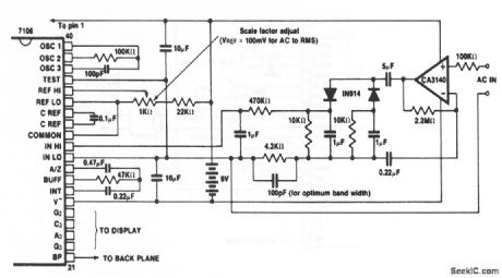
This circuit shows an ICL7106 connected to measure ac voltages, and to display the results on a 3 1/2-digit LCD. Direct connections between the ICL7106 and an LCD display are shown in Fig. 12-11B. Adjust the 1-kΩ potentiometer for the desired scale factor. Harris Semiconductors Data Acquisition, 1991 p 2-40 (View)
View full Circuit Diagram | Comments | Reading(848)
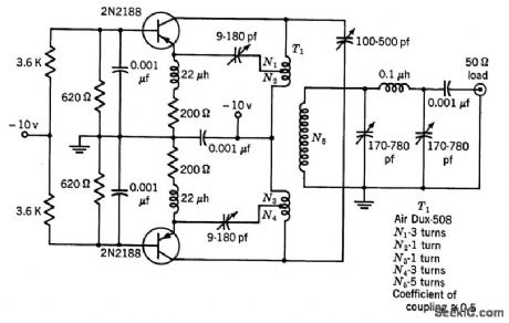
24_MC_CLAPP
Published:2009/7/19 21:45:00 Author:Jessie
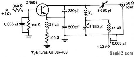
Delivers 300 mw to 50-ohm load, with collector efficiency of 35%.-Texas Instruments Inc., Transistor Circuit Design, McGraw-Hill, N.Y., 1963, p 319. (View)
View full Circuit Diagram | Comments | Reading(784)
FET_ALPHA_DETECTOR
Published:2009/7/19 21:45:00 Author:Jessie
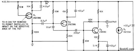
Field-effect transistor with cover removed serves as low-noise alpha-particle detector in high-altitude dew point hygrometer. Signal-to-noise ratio is 67 to 1.-C. R. Seashore and C. D. O’Brien, FET Detects Alpha Particles Better And More Precisely, Electronics, 38:3, p 64-66. (View)
View full Circuit Diagram | Comments | Reading(1565)
46_60V_FROM_62V
Published:2009/7/19 21:45:00 Author:Jessie
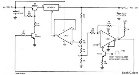
Variable-output high-voltage regulator includes short-circuit and overvoltage protection. When LM340K-24 regulator has been shut down by shorted load, LM311 must be activated by applying 4-V strobe pulse to 2N2222 transistor to make Q1 close again and start regulator.-' Linear Applications, Vol. 2, National Semiconductor, Santa Clara, CA, 1976, AN-103, p 11-12. (View)
View full Circuit Diagram | Comments | Reading(1326)
23_MC_PUSH_PULL
Published:2009/7/19 21:44:00 Author:Jessie
Delivers 75 mw to 50-ohm load, through network. –Texas Instruments Inc., Transistor Circuit Design, McGraw-Hill, N. Y., 1963, p 318. (View)
View full Circuit Diagram | Comments | Reading(974)
Digital_centigrade_thermometer
Published:2009/7/19 21:44:00 Author:Jessie
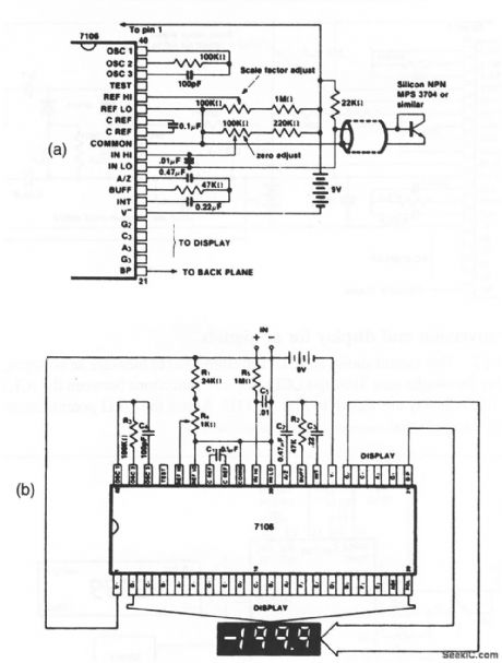
This circuit shows an ICL7106 connected with a silicon transistor to form a digital thermometer. Direct connections between the ICL7106 and an LCD display are shown in Fig. 12-11B. A diode-connected silicon transistor has a temperature coefficient of about -2 mV/℃. To achieve calibration, place the sensing transistor in ice water and adjust the zeroing potentiometer for a 000.0 reading. Then, place the sensor in boiling water and adjust the scale-factor potentiometer for a 100.0 reading. Bards Semiconductors Data Acquisition, 1991 p 2-32, 2 39 (View)
View full Circuit Diagram | Comments | Reading(1699)
15V_AT_1A_WITH_LOGIC_SHUTDOWN
Published:2009/7/19 21:43:00 Author:Jessie
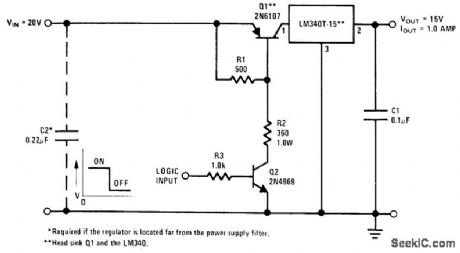
Arrangement shown provides practical method d shutting down LM340T-15 or similar regulator under control of ff L or DTL gate. Pass transistor Q1 operates as saturated transistor when logic input is high (2.4 V minimum for TTL) and Q2 is turned on. When logic input is low (below 0.4 V for TTL), Q2 andQ1 are off and regulator is in effect shut down.- Linear Applications, Vol.2, National Semiconductor, Santa Clara, CA, 1976, AN.103, p 11. (View)
View full Circuit Diagram | Comments | Reading(1448)
BRIDGED_T_AUDIO_OSCILLATOR
Published:2009/7/19 21:43:00 Author:Jessie
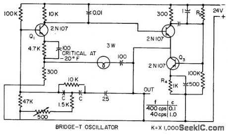
Incorporates heavy degenerative feedback in which small lamp is nonlinear compensating resistance. Provides constant output frequency and voltage for any supply between 12 and 32 V, at temperatures down to -20°F. Frequency is determined by capacitors C and 500-ohm trimmer control, to give choice of 100, 150, 230, and 350 cps.-H. P. Van Eckhardt, Crevasse Detector Blazes Glacial Trails, Electronics, 31:3, p 63-65. (View)
View full Circuit Diagram | Comments | Reading(734)
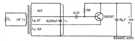
SIX_TRANSISTOR_6_V_BROADCAST_RECEIVER
Published:2009/7/20 0:50:00 Author:Jessie
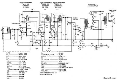
Nominal sensitivity is 200 microvolts per meter, maximum power output is 200 mw, and zero-signal battery drain is 8 ma.- Transistor Manual, Seventh Edition, General Electric Co., 1964, p 292. (View)
View full Circuit Diagram | Comments | Reading(755)
JFET_chopper_with_extended_range_of_±10_volts
Published:2009/7/19 23:07:00 Author:Jessie
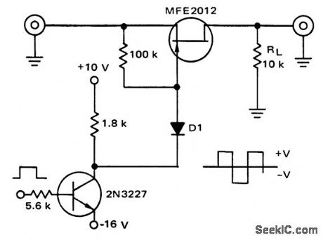
JFET chopper with extended range of ±10 volts (courtesy Motorola Semiconductor Products Inc.). (View)
View full Circuit Diagram | Comments | Reading(890)
Power_down_to_SBC_80_20_interface
Published:2009/7/19 22:23:00 Author:Jessie
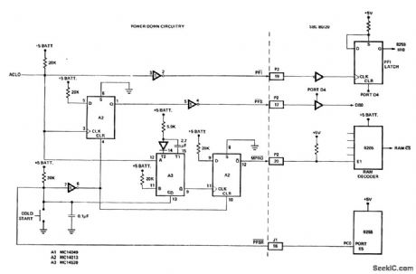
Power down to SBC 80/20 interface. The SBC 80/20 is a single board computer containing an 8259 programmable interrupt controller (courtesy Intel Corporation). (View)
View full Circuit Diagram | Comments | Reading(1137)
TUNNEL_DIODE_COINCIDENCE
Published:2009/7/19 22:21:00 Author:Jessie

Used in liquid scintillation counter for carbon-14 and other radioactive solutions delivers output pulse to stretcher ampliflier only for coinciding pulses from two photomultiplier inputs.-G. J. Sprokel, A Liquid Scintillation Counter Using Anticoincidence Shielding, IBM Journal of Research and Development, 7:2, p 135-145.
(View)
View full Circuit Diagram | Comments | Reading(690)
SClNTILLATION_COUNTER_ANTI_COINClDENCE
Published:2009/7/19 22:13:00 Author:Jessie

Produces an output from a trigger at in.put 1 only if input 2 is not triggered at that time. Used in liquid scintillation counter where expected count mtes are low.-G. J Sprokel, A Liquid Scintillation Counter Using Anticoincidence Shielding, IBM Journal of Research and Development, 7:2, p 135-145. (View)
View full Circuit Diagram | Comments | Reading(1091)
122_KC_GROUNDED_COLLECTOR_HARTLEY
Published:2009/7/19 22:08:00 Author:Jessie
Simple class-C L-C arrangement has many advantages for power oscillators and for d-c to a-c converters. One side of tank can be grounded.-P. Laakmann, Designing Class. C Transistor L-C Oscillators, Electronics, 35:30, p 42-45. (View)
View full Circuit Diagram | Comments | Reading(737)
| Pages:828/2234 At 20821822823824825826827828829830831832833834835836837838839840Under 20 |
Circuit Categories
power supply circuit
Amplifier Circuit
Basic Circuit
LED and Light Circuit
Sensor Circuit
Signal Processing
Electrical Equipment Circuit
Control Circuit
Remote Control Circuit
A/D-D/A Converter Circuit
Audio Circuit
Measuring and Test Circuit
Communication Circuit
Computer-Related Circuit
555 Circuit
Automotive Circuit
Repairing Circuit