
power supply circuit
Index 117
Morse_code_set
Published:2009/7/19 23:09:00 Author:Jessie

In this circuit, the LM3909 (connected as an oscillator) drives speakers at both sending and receiving ends, simultaneously. National semiconductor, Linear Applications Handbook, 1991 p 400 (View)
View full Circuit Diagram | Comments | Reading(0)
±15V_SYMMETRICAL_AT_1A
Published:2009/7/19 23:06:00 Author:Jessie
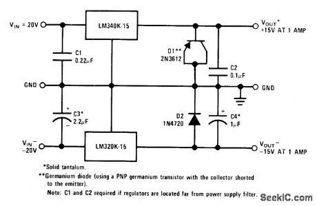
Connectionshown gives same lineand load regulation characteristics as for individual regulators. D1 ensures start-up of LM340K.15 under worst-case conditions of common load and 1.A load current over full temperature range.- Linear Applications, Vol. 2, National Semiconductor, Santa Clara, CA, 1976, AN-103, p 8. (View)
View full Circuit Diagram | Comments | Reading(1069)
Series_chopper_for_large_input_voltages_using_an_N_channel_JFET
Published:2009/7/19 23:04:00 Author:Jessie
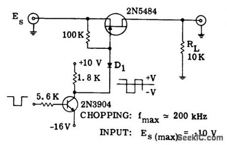
Series chopper for large input voltages using an N-channel JFET (courtesy Motorola Semiconductor Products Inc.). (View)
View full Circuit Diagram | Comments | Reading(644)
Series_shunt_chopper_for_high_frequency_applications_using_complementary_enhancement_mode_MOSFETs
Published:2009/7/19 23:03:00 Author:Jessie
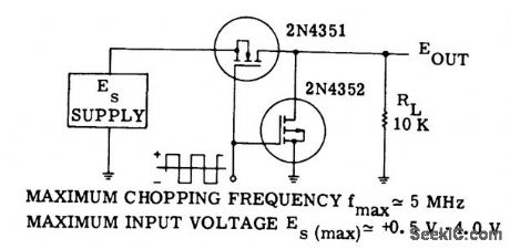
Series-shunt chopper for high-frequency applications using complementary enhancement mode MOSFETs (courtesy Motorola Semiconductor Products Inc.). (View)
View full Circuit Diagram | Comments | Reading(728)
MOSFET_analog_switching_circuit_chopper_for_large_input_voltages
Published:2009/7/19 23:00:00 Author:Jessie
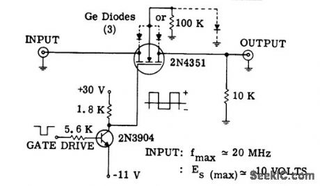
MOSFET analog switching circuit (chopper) for large input voltages (courtesy Motorola Semiconductor Products Inc.). (View)
View full Circuit Diagram | Comments | Reading(610)
FM_stereo_processor
Published:2009/7/19 22:57:00 Author:Jessie
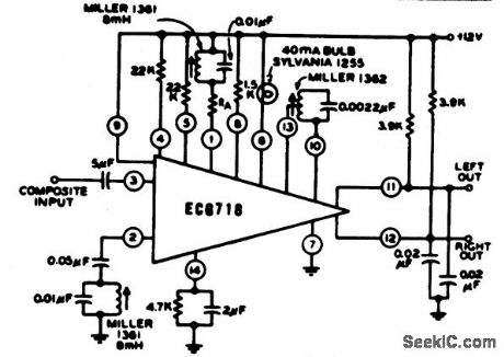
FM stereo processor. Supply voltage is typically +12 volts. The ECG718 is a 14-pin DIP with the functions of a 19 kHz amplifier, frequency doubler, stereo indicator lamp driver, audio mute, stereo/mono switch, and stereo demodulator (courtesy GTE Sylvania Incorporated). (View)
View full Circuit Diagram | Comments | Reading(1439)
FOUR_TRANSISTOR_REFLEX
Published:2009/7/19 22:57:00 Author:Jessie
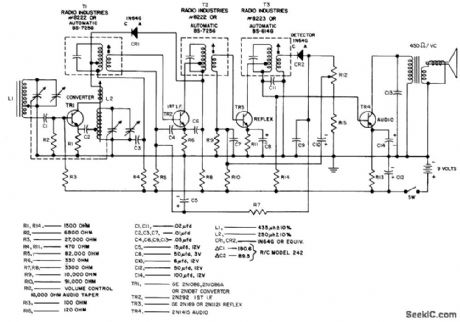
Nominal sensitivity is 200 microvolts per meter at 5 mw reference power output. Maximum power output is 75 mw, and total battery drain is 17 ma.- Transistor Manual, Seventh edition, General Electric Co., 1964, p 291. (View)
View full Circuit Diagram | Comments | Reading(656)
TRACKED_CURRENT_LIMITING
Published:2009/7/19 22:57:00 Author:Jessie
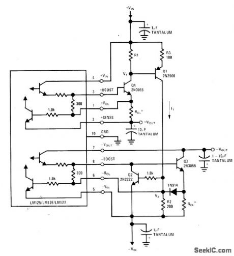
Simultaneous limiting scheme for both sections of National dual tracking regulator depends on output cur-rent of positive regulator. Voltage drop produced across R1 by positive regulator brings Q1 into conduction, with positive load current I1 increasing until voltage drop across R2 equals negative current-limit sense voltage. Negative regulator will then current-limit, and positive side will closely follow negative output down to level of about 700 mV.-T. Smathers and N. Sevastopoulos, LM125/LM126/LM127 Precision Dual Tracking Regulators, National Semiconductor, Santa Clara, CA, 1974, AN-82, p 13. (View)
View full Circuit Diagram | Comments | Reading(755)
8748_to_8251_interface
Published:2009/7/19 22:56:00 Author:Jessie
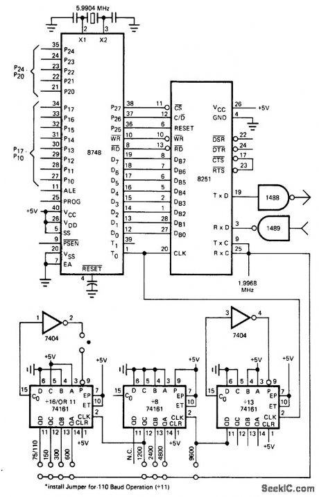
8748 to 8251 interface. The 8748 is an MCS-48 processor and the 8251 is a USART (courtesy Intel Corporation). (View)
View full Circuit Diagram | Comments | Reading(2275)
SLAVED_DUAL_TRACKING_REGULATOR
Published:2009/7/19 22:55:00 Author:Jessie
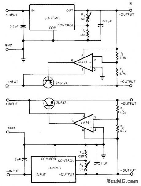


Uses Fairchild μA78MG adjustable four-terminal regulator with opamp and power transistor for delivering output currents up to 0.5 A per side, with output voltages adjustable from ±5V to ±20V for component values shown.. Positive side functions independently of negative side, but negative output is slave of positive output.To slave positive side, use μA79MG and 2N6121 NPN transistor as at (b). Opamp functions as inverting amplifier driving power transistor serving as series-pass element for opposite side of regulator, with R1 adjusting both output volt-ages simultaneously.-A. Adamian, Dual Adjustable Tracking Regulator Delivers 0.5A/Side, EDN Magazine, Jan, 5, 1977, p 42. (View)
View full Circuit Diagram | Comments | Reading(1275)
ANTENNAFIER
Published:2009/7/19 22:55:00 Author:Jessie
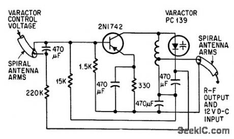
Varactor-tuned transistor amp lifer bulb into tip of conical spiral antenna is tuned from 120 to 240 Mc by varying varactor voltage from 0 to 40 v d-c.-J. F. Rippin, Making the Antenna an Active Part-net, Electronics, 38:16, p 93-96. (View)
View full Circuit Diagram | Comments | Reading(763)
Number_cruncher_interface_with_the_SC_MP_microprocessor
Published:2009/7/19 22:51:00 Author:Jessie
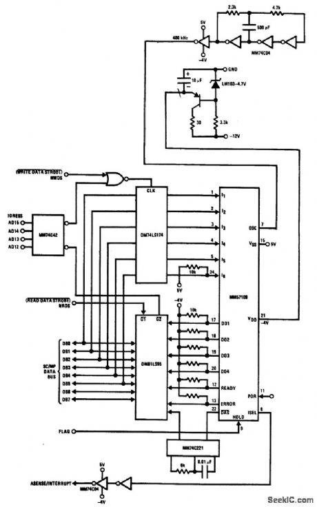
Number cruncher interface with the SC/MP microprocessor. The number cruncher unit (NCU) shown is an MM57109 (courtesy National Semiconductor Corporation). (View)
View full Circuit Diagram | Comments | Reading(1203)
TONE_SIGNAL_REJECTOR
Published:2009/7/19 22:49:00 Author:Jessie
Used to separate desired backscatter pulses from unwanted tone signals of interfering stations on same frequency. Negative-going portion of tone signal is rectified and used us slicer level for passing desired pulse, which rides on top of interfering tone.-K. Perry, Reducing Interference in Ionospheric Sounding, 33:22, Electronics, p 118-120. (View)
View full Circuit Diagram | Comments | Reading(664)
±24V_REGULATED_AND_±35V_UNREGULATED
Published:2009/7/19 22:48:00 Author:Jessie
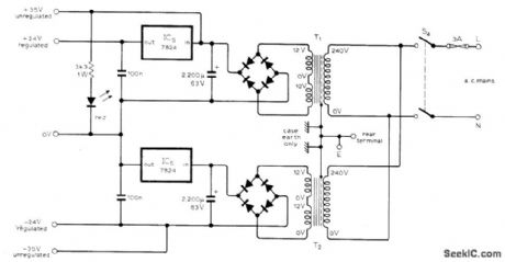
Developed for use with high-performance stereo preamp. Each IC regulator re quires about 7 cm2 of heatsink area. Red LED is TIL209 or equivalent.-D Self, Advanced Preamplifier Design Wireless World,Nov,1976 p41-46. (View)
View full Circuit Diagram | Comments | Reading(989)
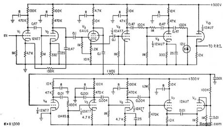
AUDIO_FOR_A_M_F_M_PORTABLE
Published:2009/7/19 22:48:00 Author:Jessie

Overall power gain is 70 db, with audio output of 1 w at less than 10% distortion.-R. A. Santilli and H. Thanos, Portable Radio Uses Drift-Field Transistors, Electronics, 33:28, p 48-50. (View)
View full Circuit Diagram | Comments | Reading(658)
Teletypewriter_RS_232C_terminal_to_MC6850_ACIA_interface
Published:2009/7/19 22:47:00 Author:Jessie
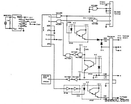
Teletypewriter/RS-232C terminal to MC6850 ACIA interface (courtesy Motorola Semiconductor Products Inc.). (View)
View full Circuit Diagram | Comments | Reading(1225)
THREE_TRANSISTOR_A_M_F_M_I_F_STRIP
Published:2009/7/19 22:46:00 Author:Jessie
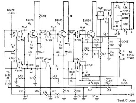
Used in a-m/f-m portable radio. Only two stages operate on a-m.-R. A. Santilli and H. Thanos, Portable Radio Uses Drift-Field Transistors, Electronics, 33:28, p 48-50. (View)
View full Circuit Diagram | Comments | Reading(660)
5V_AT_5A
Published:2009/7/19 22:46:00 Author:Jessie
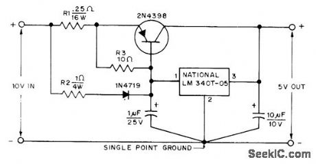
Current-sharing design provides short-circuit protection, safe-operating-area protection, and thermal shutdown. Typical load regulation is 1.4%.-W. R. Calbo, A High-Cur-rent, Low-Voltage Regulator for TTL Circuits, QST, Sept. 1975, p 44 (View)
View full Circuit Diagram | Comments | Reading(756)
45_34V_VARIABLE_AT_1A
Published:2009/7/19 22:45:00 Author:Jessie
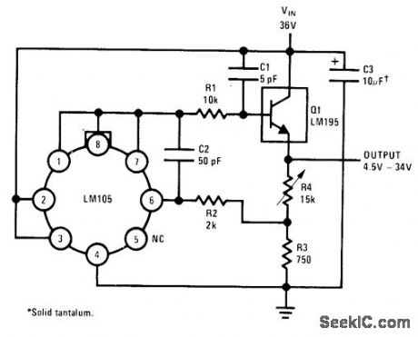
National LM195 power transistor is used with LM105 regulator to give fully adjustable range of output voltages with overload protection and only 2-V input-to-output voltage differential. Load regulation is better than 2 mV.-R. Dobkin, Fast IC Power Transistor with Thermal Protection, National Semiconductor, Santa Clara, CA, 1974, AN-110, p4. (View)
View full Circuit Diagram | Comments | Reading(718)
28V_AT_7A
Published:2009/7/19 22:44:00 Author:Jessie
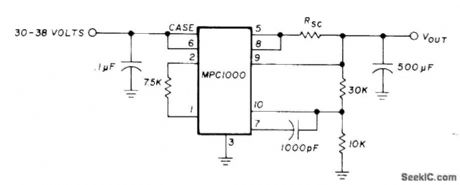
Uses Motorola MPC1000 positive voltage regulator to provide regulated voltage for aircraft radio equipment being used at ground station. Current-limiting resistor RSC is in range of 0.66 to 0.066 ohm. Use copper wire about 50% longer than calculated length and shorten step by step until required pass current is obtained; thus, start with 25 ft of No. 16, 15 ft of No. 18, 10ft of No. 20, or 6ft of No. 22. Input voltage is obtained from 30-V transformer and bridge rectifier.-G. L. Tater, The MPC1000-Super Regulator, Ham Radio, Sept. 1976, p 52-54. (View)
View full Circuit Diagram | Comments | Reading(867)
| Pages:117/291 At 20101102103104105106107108109110111112113114115116117118119120Under 20 |
Circuit Categories
power supply circuit
Amplifier Circuit
Basic Circuit
LED and Light Circuit
Sensor Circuit
Signal Processing
Electrical Equipment Circuit
Control Circuit
Remote Control Circuit
A/D-D/A Converter Circuit
Audio Circuit
Measuring and Test Circuit
Communication Circuit
Computer-Related Circuit
555 Circuit
Automotive Circuit
Repairing Circuit