
Electrical Equipment Circuit
Index 113
The ABS Circuit of the Citroen-Elysee Car
Published:2011/5/8 9:42:00 Author:Borg | Keyword: ABS Circuit, Citroen-Elysee
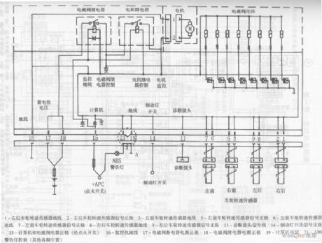
The ABS Circuit of the Citroen-Elysee Car (View)
View full Circuit Diagram | Comments | Reading(1113)
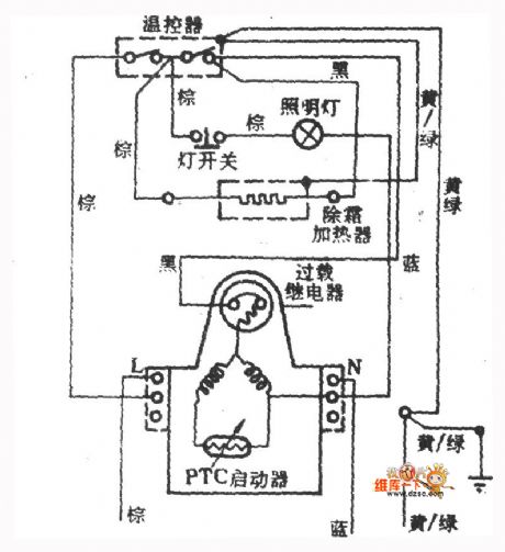
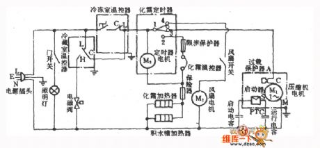
zhongyi BCD-215 fridge circuit diagram
Published:2011/5/7 21:25:00 Author: | Keyword: fridge, circuit

View full Circuit Diagram | Comments | Reading(634)
Using NE555 Skillfully as Linear Capacitance Tester Circuit
Published:2011/5/5 2:54:00 Author:Joyce | Keyword: Using NE555 Skillfully as, Linear, Capacitance, Tester
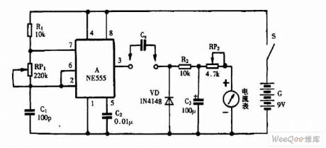
Using NE555 Skillfully as Linear Capacitance Tester Circuit (View)
View full Circuit Diagram | Comments | Reading(3779)
Using NE555 Skillfully as Speaker Protector Circuit
Published:2011/5/5 2:56:00 Author:Joyce | Keyword: Using NE555 Skillfully as, Speaker, Protector
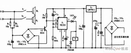
Using NE555 Skillfully as Speaker Protector Circuit (View)
View full Circuit Diagram | Comments | Reading(5168)
Using ZH-3 Skillfully as Darkroom Temperature Display Circuit
Published:2011/5/5 2:57:00 Author:Joyce | Keyword: Using ZH-3 Skillfully as, Darkroom, Temperature, Display
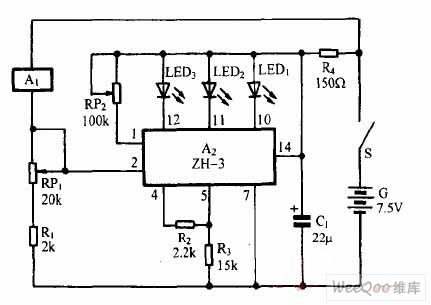
Using ZH-3 Skillfully as Darkroom Temperature Display Circuit (View)
View full Circuit Diagram | Comments | Reading(528)
Yangzi BCD-200 fridge circuit diagram
Published:2011/5/5 8:49:00 Author: | Keyword: fridge, circuit
View full Circuit Diagram | Comments | Reading(542)
1.5V liquid crystal display circuit
Published:2011/5/3 3:30:00 Author:muriel | Keyword: 1.5V , liquid crystal display circuit, MC14440
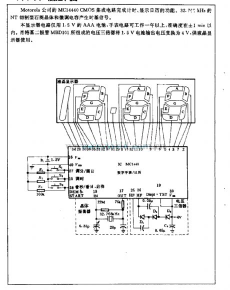
The Motorola company's MC14440 CMOS integrated circuit has the function of timing and displaying the calendar. The 32.760 kHz NT cutting type quartz crystal and fine-tune capacitance can produce time-based signal.The display circuit only uses 1.5 V AAA battery, watch circuit can workfor more than one year, the accuracyof it is within ±1min.The voltage tripler which is composed of the schottky diode MBD101, can transform the 1.5 V battery output voltage to 4V, supply to LCD using. (View)
View full Circuit Diagram | Comments | Reading(1417)
Same Polarity Driving Circuit
Published:2011/5/5 0:59:00 Author:Robert | Keyword: Same Polarity, Driving
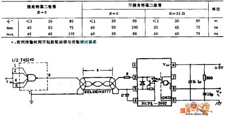
The 74S140 driver with the same polarity, through the shielded cable, twisted-paircable or coaxial cable, transmits data to the HCPL-2602 optocoupler wide receiver in a high speed data transmission. The reflex action caused by active-ended receiver would not affect its performance. By connecting to a capacitor C and a resistance R in series could make its data transmission speed up to highest possible speed. The C should be as large as possible, and do not prevent the voltage regulator tube's shutoff during input signal negative bias. If try to let tPHL=tPLH, that can achieve the highest data transmission speed.
(View)
View full Circuit Diagram | Comments | Reading(638)
Transformer Equivalent Circuit
Published:2011/5/4 21:59:00 Author:Robert | Keyword: Transformer, Equivalent
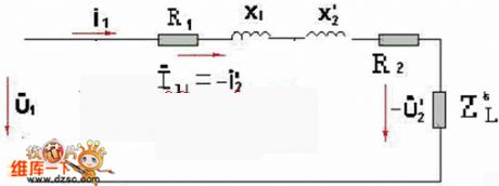
Transformer equivalent circuit is shown below.The approximate equivalent circuit can be used to calculate and analyze some issues of the transformer load operation, such as changes in the secondary side voltage of the parallel load distribution etc. which move the excitation branch to the end point. Little calculation error caused by calculation: the transformer's excitation current (which means the current with no load) is 2%-10% of the rated current. (Less than 1% for large transformer).
(View)
View full Circuit Diagram | Comments | Reading(1028)
spaceflight BCD-218W fridge circuit diagram
Published:2011/5/4 9:48:00 Author: | Keyword: fridge, circuit
View full Circuit Diagram | Comments | Reading(561)
SHEA-3200 electric pot circuit diagram
Published:2011/5/4 9:31:00 Author:Nancy | Keyword: electric pot
View full Circuit Diagram | Comments | Reading(712)
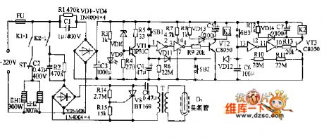
bifunctional electronic sterilizer circuit diagram
Published:2011/5/4 9:22:00 Author:Nancy | Keyword: bifunctional, electronic sterilizer
View full Circuit Diagram | Comments | Reading(698)
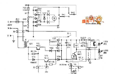
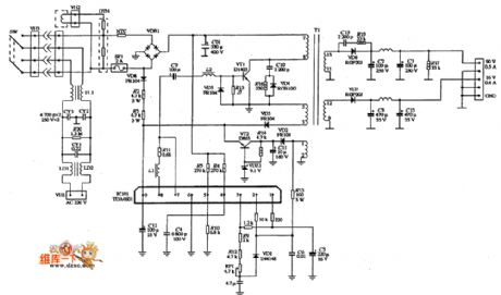
SUNLIHT SM-348 power supply circuit diagram
Published:2011/5/4 9:47:00 Author:Nancy | Keyword: SUNLIHT, power supply
View full Circuit Diagram | Comments | Reading(756)
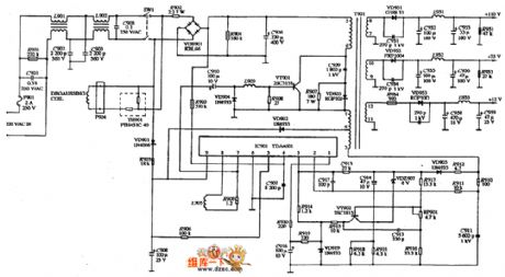
SUNLIHT SM-546 power supply circuit diagram
Published:2011/5/4 9:49:00 Author:Nancy | Keyword: SUNLIHT, power supply
View full Circuit Diagram | Comments | Reading(608)
Fun little toy circuit diagram
Published:2011/5/4 3:04:00 Author:Ecco | Keyword: Fun , little toy
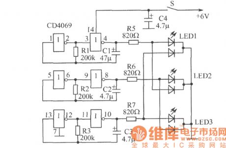
The circuit shows the fun little toy circuit. Closing the power switch, three small lights will emit randomly red, green, orange light. It mainly consists of six inverter digital integrated circuit CD4069 and three color light-emitting diodes and other components. Component selection: Manifold uses CD4069 digital integrated circuit, the manifold is a typical CMOS circuit. LED can choose 2EF301 discolor light-emitting diodes. Resistors use small-volume (1 / 8) W carbon resistors, capacitor uses CD11-10V electrolytic capacitor. Power supply uses 4 pieces of 5th battery. Other components are shown as the chart.
(View)
View full Circuit Diagram | Comments | Reading(930)
Differential exposure meter circuit
Published:2011/5/3 6:18:00 Author:Christina | Keyword: Differential, exposure meter
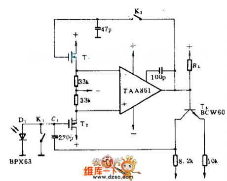
The BPX63 photodiode's sensitivityis 10mA/IX. This circuit ensures that the figure Location only affected by the useful light but not affected by the noise signal. When the circuit is under the low light condition, this circuit can collects a series of short pulse light rapidly. When the camera shutter is not open, K1, K2 closed, so the output of the operational amplifier tied back to its input port. At the beginning of the exposure, K1 and K2 open, the circuit produces more than 3000 times magnification. So the integration capacitor C1 charged by the photocurrent to make the output voltage changed by the time. When the output voltage is 1V, T3's base-emitter starts to conduct. When the C1 feeds back through T3, the RL stops, so the exposure stops, power supply is +/-3V.
(View)
View full Circuit Diagram | Comments | Reading(734)
Circuit of Wireless Stereo Speakers
Published:2011/5/3 2:49:00 Author:Felicity | Keyword: Circuit of Wireless Stereo Speakers,
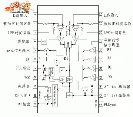
Circuit of Wireless Stereo Speakers is showed in the picture above. (View)
View full Circuit Diagram | Comments | Reading(664)
Partial pressure temperature protection relay circuit diagram
Published:2011/5/3 2:35:00 Author:Rebekka | Keyword: Temperature protection relay, Partial pressure
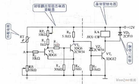
Partial pressure temperature protection relay circuit diagram. (View)
View full Circuit Diagram | Comments | Reading(1413)
Circuit of D201 Ultrasonic Humidifier
Published:2011/5/3 2:22:00 Author:Felicity | Keyword: Circuit of Ultrasonic Humidifier
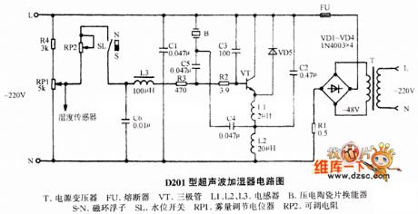
Circuit of D201 Ultrosonic Hulmidifier is showed in the picture above. (View)
View full Circuit Diagram | Comments | Reading(5692)
Light Control Switch Circuit Of Photodiode BPX63
Published:2011/5/1 22:44:00 Author:Christina | Keyword: Photodiode BPX63, Light Control Switch
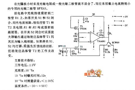
It is improper to use the photoresistor or general photodiode when the light intensity is minimum, and you should use the photodiode BPX63 which has very small cut-off current.
In this circuit, light continuously shine on the diode D1, if swich S1 and S2 close, the photocurrent will short circuit, FET T1,T2 and resistor R1,R2 constitute a source emitter follower. When the switch S2 closed, output power of op amp through the field-effect transistor T1 to connect the reverse input port. If swich S1,S2 open, the strong negative feedback circuit will be cut off, however, the work point of the field-effect transistor T2 will be change.
(View)
View full Circuit Diagram | Comments | Reading(1281)
| Pages:113/126 At 20101102103104105106107108109110111112113114115116117118119120Under 20 |
Circuit Categories
power supply circuit
Amplifier Circuit
Basic Circuit
LED and Light Circuit
Sensor Circuit
Signal Processing
Electrical Equipment Circuit
Control Circuit
Remote Control Circuit
A/D-D/A Converter Circuit
Audio Circuit
Measuring and Test Circuit
Communication Circuit
Computer-Related Circuit
555 Circuit
Automotive Circuit
Repairing Circuit