
Electrical Equipment Circuit
Index 115
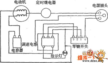
Two Level breeze gear three-speed fan circuit
Published:2011/4/1 1:08:00 Author:may | Keyword: Two Level breeze gear three-speed fan

Two Level breeze file three-speed fan circuit is shown in the diagram:
(View)
View full Circuit Diagram | Comments | Reading(2033)
Electric fan speed regulation circuit
Published:2011/4/11 2:23:00 Author:may | Keyword: Electric fan, speed regulation
Electric fan speed regulation circuit is shown in the diagram:
(View)
View full Circuit Diagram | Comments | Reading(590)
High power speed governor circuit used in cleaner
Published:2011/4/11 2:25:00 Author:may | Keyword: High power, speed governor
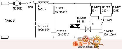
By changing the gear of sw1 can control the revolving speed of of electric motor and get various pipe suction. (View)
View full Circuit Diagram | Comments | Reading(733)
Electric fan serial and parallel connection method speed regulation circuit
Published:2011/4/11 2:22:00 Author:may | Keyword: Electric fan, serial, parallel connection method, speed regulation
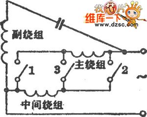
Electric fan serial and parallel connection method speed regulation circuit is shown in the diagram:
(View)
View full Circuit Diagram | Comments | Reading(651)
The simple air control circuit of ventilator
Published:2011/4/2 4:32:00 Author:may | Keyword: air control, ventilator
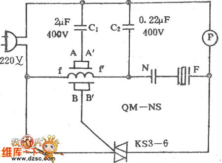
The simple air control circuit of ventilator is shown in the following diagram:
(View)
View full Circuit Diagram | Comments | Reading(757)
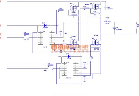
Five functions refrigerator protection(CD4060,C043,C033)
Published:2011/4/26 4:07:00 Author:Ecco | Keyword: Five functions, refrigerator, protection
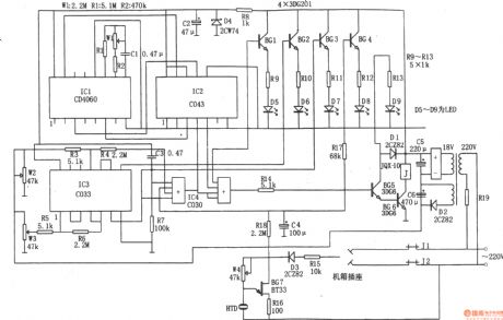
The circuit shown as the chart is the five functional refrigerator protection circuit. The protection is composed of the time base signal generator, power voltage monitoring circuit, shaping circuit, the electrical control circuit, leakage alarm circuit. The time base signal generator is composed of IC1 (CD4060) and R1, R2, W1, C1 and so on. It can produce 3 kinds of time signals with 5 minutes and 40 seconds, 22 minutes and 30 seconds and 12 hours, time signals is combined by the IC2 (C043) logically, the output from the IC2 ⑨ feet every 12 hours 22 minutes and 30 seconds defrost time can control signal. Supply voltage monitoring circuit is composed of the IC3 (C033) and W2, W3, R5, R6, etc., of which W2, W3, respectively are the up and down limit preset potentiometers. When the grid voltage changes in the range of 175 ~ 245V, IC3 ⑥, ⑧ feet are 0V, no control signal is output. When the grid voltage falls below 175V, IC3 ⑥ pin outputs control signal. When the grid voltage is above 245V, IC3 ⑧ feet outputs control signals. Leakage alarm circuit is composed of the BG7, D3, HTD, W4 and so on. In case of leakage, the leakage current flowing through D3 is rectified to make BG7 oscillations, it drives piezoelectric HTD to make alarm sound.
(View)
View full Circuit Diagram | Comments | Reading(2184)
Automatic hand dryer circuit diagram
Published:2011/4/22 3:41:00 Author:Ecco | Keyword: Automatic, hand dryer
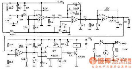
Infrared emission part generates a square wave signal with 50% duty cycle and 5kHz frequency by 555 circuit. And the signal drives the red launch tube to emit the infrared ray.
When the hand placed under the dryers, as the hand has the reflecting effect to infrared ray, the PH302 in receiver circuit will receive the infrared signal change it into electrical signal, and it passes the selected frequency amplifier composed of IC1, IC2, IC3, the output signal being a DC signal and gets into the comparator IC4 by amplified, shaped, filtered. Comparator threshold voltage is 7V, setting high aims to improve the circuit's noise immunity. When IC4 input level exceeds 7V, the output goes low, the rocks make IC5 timer start timing, while 3 feet of the timer goes high to make 3DG130 turn, pull-point of relay pulls in to connect to resistance wire. (View)
View full Circuit Diagram | Comments | Reading(5473)
Electronic smooth wheezing device
Published:2011/4/26 21:54:00 Author:Ecco | Keyword: Electronic , smooth wheezing device
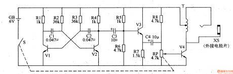
This example describes an electronic smooth wheezing device which is made by discrete electronic components, it produces high-voltage stimulation pulse, which can play the role of adjuvant therapy for cough patient. The working principleThe electronic smooth wheezing device circuit is composed of self-excited multivibrator, the buffer amplifier and voltage generator circuit, it is shown as Figure 9-156.
Self-excited multivibrator is composed of the transistor Vl, V2, capacitors Cl, C2 and resistors Rl-R4 and so on. Buffer amplifier circuit is composed of the emitter amplification tube V3, bias resistor R6 and geese coupling capacitors C3, C4. High-voltage generating circuit is composed of the potentiometer RP, resistors R8, amplified output tube V4, the garnet-type step-up transformer T and output socket XS. Self-excited multivibrator can generate the oscillation signal with frequency in 5OOHz, and it is amplified by the V3, V4 and transformer T, the outlet XS outputs pulse voltage which is more than lOOV.
Rl-R8 select 1/4W carbon film resistors or metal film resistors. RP selects WH-l5 series or WTR series of small synthetic carbon with switch potentiometer. Cl and C2 choose polyester capacitors or monolithic capacitors; C3 and C4 select the electrolytic capacitors with voltage value being greater than lOV. Vl-V3 use 3DG6 or S9014 silicon NPN transistor; V4 chooses S805O or C8050, 3DGl2 and other silicon NPN transistor. (View)
View full Circuit Diagram | Comments | Reading(1000)
Electronic hypnotic device 5
Published:2011/4/26 6:15:00 Author:Ecco | Keyword: Electronic , hypnotic device
The working principle.
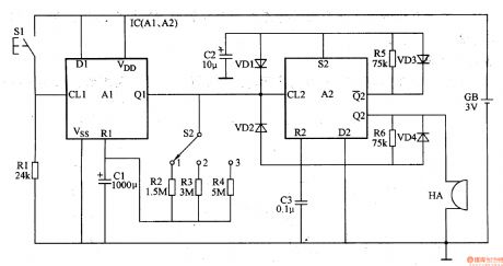
The electronic hypnotic device is composed of monostable circuit, self-excited multivibrator circuit and buzzer HA and other components, it is shown in Figure 9-142.
Monostable circuit is composed of dual D flip-flop integrated circuit IC (Al, A2) and resistors Rl-R4, capacitor Cl, control button 51 and delay time selection switch 52. Self-excited multivibrator circuit is composed of the other D flip-flop A2 inside the IC and diodes VDl-VD4, resistors R5, R6, capacitors C2, C3. Pressing button S1, the flip is triggered by the monostable circuit, IC's Ql outputs high level, the multi-harmonic oscillator works, the Q2 of IC outputs 2Hz oscillation frequency signal, the driver HA issues a similar sound of raindrops to help people sleep. When the charging of Cl is over, one-shot circuit returns to steady state, IC's Ql outputs low level again, multi-harmonic oscillator stops working, HA stops the sound. (View)
View full Circuit Diagram | Comments | Reading(1406)
Refrigerator working indicator light circuit
Published:2011/4/26 4:22:00 Author:Nicole | Keyword: refrigerator, indicator light
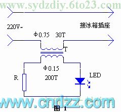
Adding a working indicator light to refrigerator power supply scoket is not only convenient to observe the refrigerator's start and stop, but also can increase the aesthetic feeling of socket.
The circuit is as shown in figure 1. LED is lighted up by the secondary induced current of current transformer. The current transformer can use a larger transistor radio input or output transformer, to reform it accordng to the graphic data. Pay attention to the interwinding is insulated.
(View)
View full Circuit Diagram | Comments | Reading(904)
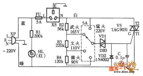
Xinmei VL-95Q electric rice and porridge cooker circuit diagram
Published:2011/4/26 10:23:00 Author:Nancy | Keyword: electric rice cooker, porridge cooker
View full Circuit Diagram | Comments | Reading(1765)
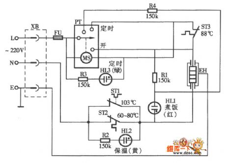
Timer automatic electric rice cooker circuit diagram
Published:2011/4/26 10:24:00 Author:Nancy | Keyword: Timer, automatic, electric rice cooker
View full Circuit Diagram | Comments | Reading(8158)
8W Mobile Small Size Emergency Lamp Circuit
Published:2011/4/26 7:23:00 Author:Robert | Keyword: 8W, Mobile, Small Size, Emergency Lamp
In this picture d1 is the charging pilot light. In the status of charging, as the battery voltage increased gradually, thebrightness of d1 would decrease gradually, until entirelygo out.
(View)
View full Circuit Diagram | Comments | Reading(1757)
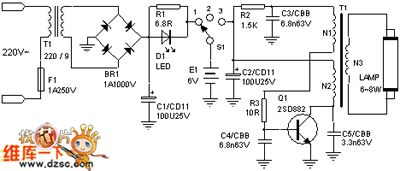
6W Mobile Small Size Emergency Lamp Circuit
Published:2011/4/26 9:41:00 Author:Robert | Keyword: 6W, Mobile, Small Size, Emergency Lamp
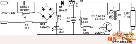
6W Mobile Small Size Emergency Lamp has the following features: small size and lightweight, high brightness, affordable, and it could be used generally in the country side or those areas of frequent power outages.
1.The circuit is shown below.
2.Principle of work
When the power plug connects to the 220V city power, the LED indicator would be lighted, at this time if turn the switch to the left side, the battery could be charging; when used outside, turn the switch to the right side, the emergency lamp starts to work, and the power could be closed while turning the switch to the left side.
(View)
View full Circuit Diagram | Comments | Reading(1512)
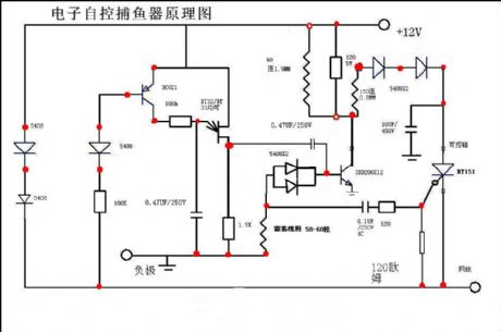
Electronic fishing device
Published:2011/4/26 3:42:00 Author:May | Keyword: Electronic, fishing device
View full Circuit Diagram | Comments | Reading(1367)
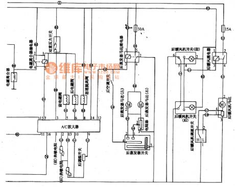
Shenyang JinBei SY6480 light car air conditioning amplifier,back evaporator,back warm braw circuit diagram
Published:2011/4/26 3:19:00 Author:Nicole | Keyword: Shenyang JinBei, light car, air conditioning amplifier, evaporator, warm braw
View full Circuit Diagram | Comments | Reading(1360)
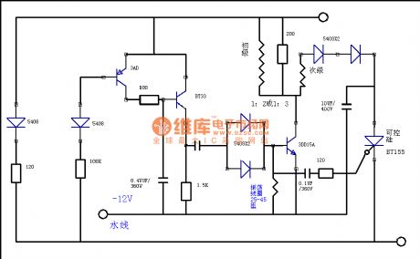
Electronic controlled fishing device
Published:2011/4/25 2:55:00 Author:May | Keyword: Electronic controlled, fishing device
View full Circuit Diagram | Comments | Reading(2600)
Fish trap 2
Published:2011/4/25 2:42:00 Author:May | Keyword: Fish trap 2

View full Circuit Diagram | Comments | Reading(1096)
Fish trap
Published:2011/4/25 2:41:00 Author:May | Keyword: Fish trap
View full Circuit Diagram | Comments | Reading(959)
555 ambulance audio circuit
Published:2011/4/25 1:41:00 Author:May | Keyword: 555, ambulance audio
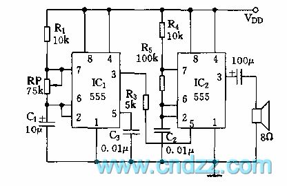
As shown in diagram 21-1, this circuit consists of two ambipolar 555, and it all works at multivbrator state. It is not hard to equate frequency of two oscillators by parameter in the diagram.
f1=1/T=1.44/[(R2+Rp)C1]
When resistance of potentiometer RP changes in the range of 0~75kΩ, corresponding frequency is 14.4Hz~0.9Hz.
f2=1.44/[(R2+2R5)C2]≈700Hz
IC2 is controlled by low frequency square wave of IC1. When output square wave of IC1 is low level, oscillating frequency of IC2 is low; and when output of IC1 is high level, oscillating frequency of IC2 is high ,so the loudspeaker can send out rhythm sound of di-da, di-da . Output sound frequency can change by changing the time constant of R4, R5 and C2. (View)
View full Circuit Diagram | Comments | Reading(1057)
| Pages:115/126 At 20101102103104105106107108109110111112113114115116117118119120Under 20 |
Circuit Categories
power supply circuit
Amplifier Circuit
Basic Circuit
LED and Light Circuit
Sensor Circuit
Signal Processing
Electrical Equipment Circuit
Control Circuit
Remote Control Circuit
A/D-D/A Converter Circuit
Audio Circuit
Measuring and Test Circuit
Communication Circuit
Computer-Related Circuit
555 Circuit
Automotive Circuit
Repairing Circuit