
Electrical Equipment Circuit
Index 116
TEA2107 Application Circuit
Published:2011/4/22 5:12:00 Author:Robert | Keyword: Application
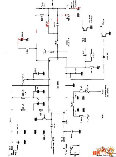
TEA2107 application circuitis shown above. (View)
View full Circuit Diagram | Comments | Reading(986)
Light intensity control switch circuit
Published:2011/4/24 10:06:00 Author:Christina | Keyword: Light intensity, control switch
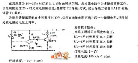
When the light intensity is 10-25lx, The bulb's frequency of flashing is 1.5Hz. At this point this circuit works as the multivibrator. When the light intensity is over 25lx, resistance of the photosensitive resistor become lower, transistor T2 turns on, the light turns off. The circuit close the transistor T1 by diode BA127.
To let the multivibrator work under small illumination, we must parallel a fine-tuning resistance at both ends of the photoresistor to limit the resistance increase rate.
Main technical data:
The light intensity and voltage when the circuit shut down:
when UB=4V, light intensity is 45lx
when UB=5V, light intensity is 25lx
when UB=6V, light intensity is 15lx
Lamp voltage: 2V to 4V
Current consumption (100lx): <10mA
(View)
View full Circuit Diagram | Comments | Reading(807)
The refrigerator temperature telling circuit(LM324,SL322)
Published:2011/4/25 3:55:00 Author:Ecco | Keyword: refrigerator, temperature, telling circuit
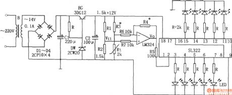
Refrigerator temperature telling circuit is shown as the chart. The circuit consists of step-down circuit, temperature sensing elements Rt, integrated operational amplifier LM324, IC SL322-level display and so on. Buck rectifier circuit provides DC voltage for the entire circuit; Rt is the thermal resistor, SL322 is used to drive light emitting diodes. When the refrigerator temperature increases, the resistance of Rt decrease, the corresponding Vi1 declines, it is amplified by LM324, the voltage Vo rises, Vo is directly sent into the SL322 to drive light emitting diodes, and the input voltage rises due to SL322, the number of lit LEDs increases. Conversely, when the refrigerator temperature is lowered, the number of lit LEDs declines. Determining the temperature of light-emitting diode, the number of lit LEDs can tell the temperature inside the refrigerator. The circuit shown as the chart only has one lit light when at 0 ℃, 10 LED lights at 18 ℃, the average change every 2 ℃ will cause l LED being lit or off. If you want to lower the temperature and more lit LEDs, R3 and R4 may be changed the positions.
(View)
View full Circuit Diagram | Comments | Reading(5710)
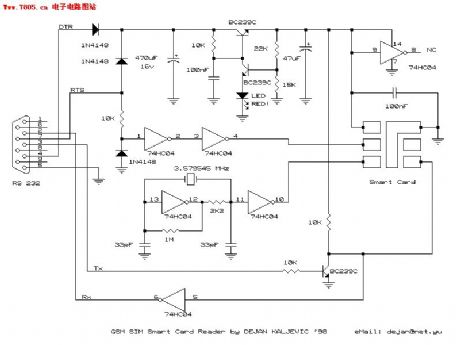
The DIY information of SIMMAX on GSM mobile phone
Published:2011/4/24 21:16:00 Author:Ecco | Keyword: DIY information , SIMMAX , GSM mobile phone
View full Circuit Diagram | Comments | Reading(1065)
Driven by Op Amp High-performance Amplifier Circuit
Published:2011/4/24 20:48:00 Author:Christina | Keyword: Op Amp, High-performance Amplifier
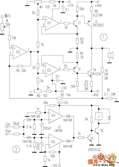
Conventional op amp drive amplifier' power is difficult to expand because of the limit of op amp voltage. This power amplifier uses the Voltage switching current mode to drive the tube amplifier directly, so the output power depends on final amplifier tube and amplifier power, and the speaker has no on / off shock noise. The whole device does not add any compensation capacitor, so the phase shift is small. And this device uses the op amp as the constant current amplifier, so we can change different op amps easily, there are more choices of Timbre.
The op amp uses the ne5532 or ad827 dual op amp, t1, t2 use the medium power transistor 2sb647, 2sd667, and the final amplifier tube are the sanken tube 2sc2922, 2sa1216 or 2sc3281, 2sa1302, and the resistance uses the 1/4w metal film resistor.
(View)
View full Circuit Diagram | Comments | Reading(3570)
Eye Protechtion Circuit
Published:2011/4/23 3:11:00 Author:Robert | Keyword: Eye Protechtion
Eye Protechtion Circuit is shown below:
(View)
View full Circuit Diagram | Comments | Reading(633)
Rocket Launcher Simulation Circuit
Published:2011/4/23 3:13:00 Author:Robert | Keyword: Rocket Launcher, Simulation
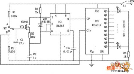
Rocket Launcher Simulation Circuit is shown as below:
(View)
View full Circuit Diagram | Comments | Reading(762)
Car Anti-Collision Untrasonic Wave Circuit
Published:2011/4/23 3:35:00 Author:Robert | Keyword: Car, Anti-Collision, Untrasonic Wave
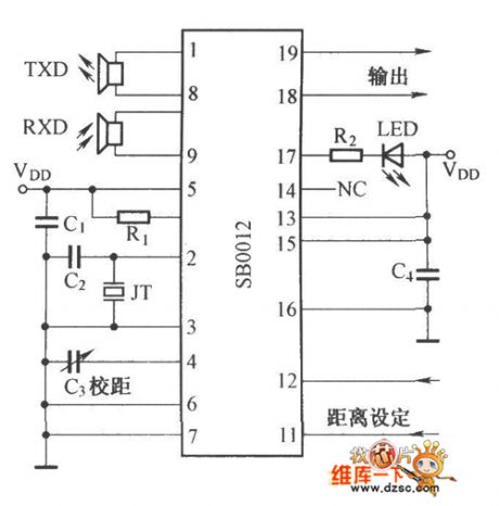
Car Anti-Collision Untrasonic Wave Circuit is shown below:
(View)
View full Circuit Diagram | Comments | Reading(1182)
Ultrasonic Wave Anti-Theft Alarm Detector Circuit
Published:2011/4/23 9:58:00 Author:Robert | Keyword: Ultrasonic Wave, Anti-Theft, Alarm, Detector
Ultrasonic Wave Anti-Theft Alarm Detector Circuit is shown below:
(View)
View full Circuit Diagram | Comments | Reading(748)
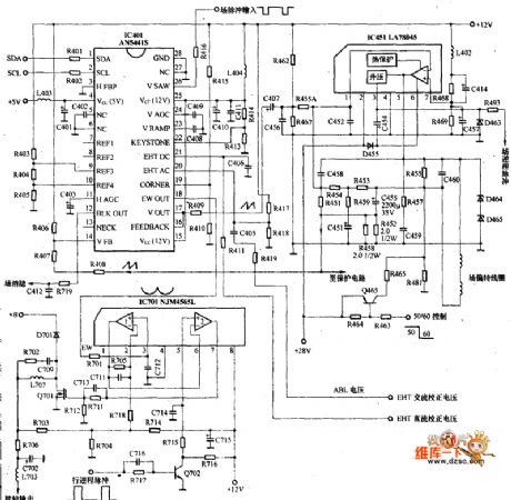
Panasonic mx8c Core Field Scanning Circuit And Pincushion Correction Circuit
Published:2011/4/21 20:15:00 Author:Robert | Keyword: Core Field Scanning, Pincushion Correction
View full Circuit Diagram | Comments | Reading(590)
Solenoid Switch Circuit
Published:2011/4/21 9:48:00 Author:Christina | Keyword: Solenoid, Switch Circuit
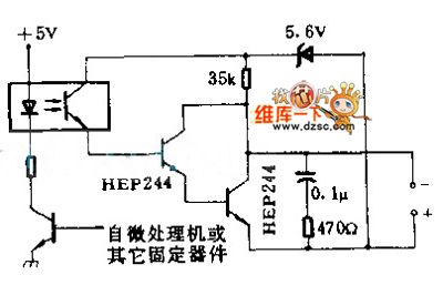
When the switch teleprinter is inductive load, the optical isolator provides the protection relay between the teleprinter and 8080A or other microprocessors. The RC filter which across the darlington transistor accelerates the reset speed of print magnet.
(View)
View full Circuit Diagram | Comments | Reading(690)
Microprocessor electric typewriter circuit
Published:2011/4/21 4:23:00 Author:Nicole | Keyword: microprocessor, electric typewriter
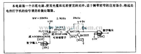
This circuit is a model circuit, it adopts fiber optic cable and some cheaper components and it is used in the occasions with narrow frequency band, it feeds the microprocessor with singal of forane electric typewriter. (View)
View full Circuit Diagram | Comments | Reading(708)
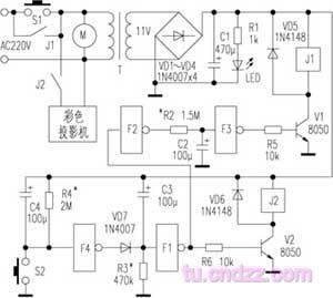
Colour TV power supply controller circuit
Published:2011/3/30 1:28:00 Author:may | Keyword: Colour TV power supply controller
View full Circuit Diagram | Comments | Reading(1602)
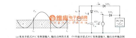
Relationship of multiple system PFC convertor input, output power
Published:2011/3/30 22:00:00 Author:may | Keyword: multiple system, PFC convertor
View full Circuit Diagram | Comments | Reading(527)
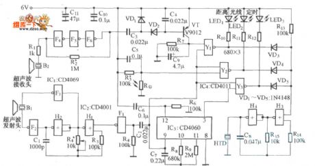
Infrared reflector type of electronic bell circuit diagram
Published:2011/3/30 22:55:00 Author:Ecco | Keyword: Infrared reflector type , electronic bell
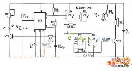
The infrared reflector type of electronic bell, can transmit voice frequency semaphore to tell host that vistors are coming in definite distance. The bell is also a type of annunciator. The working principle is that infrared reflector type of electronic bell consisting of infrared emission circuitry, infrared receive circuitry, low frequency oscillator, audio oscillator, audio output circuitry. etc. According to the chart:
(View)
View full Circuit Diagram | Comments | Reading(1277)
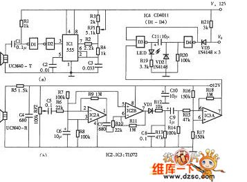
Clairaudit audiphone circuit diagram
Published:2011/3/30 22:21:00 Author:Ecco | Keyword: Clairaudit audiphone
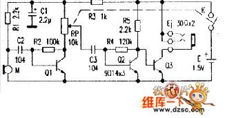
The Clairaudit audiphone is composed of discrete component with simple structure and small volume. The circuit diagram is decided according the material object, it's provided forreference while coping now.
In the figure, microphone could receive aural signal. Q1 and Q2 make up second order audio amplifier. As power amplifier, Q3 amplifies the aural signalandlistened by stereophone, and Rp can rectify the volume. Under normal working circumstance, the voltage of Q1, Q2 is 0.5V, and the quiescent current is 10mA. When the voltage falls to 1.1 V, the sound in the earphone is still clear. (View)
View full Circuit Diagram | Comments | Reading(612)
Simple hypnotic machine circuit diagram
Published:2011/3/30 22:29:00 Author:Ecco | Keyword: hypnotic machine
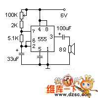
Time base circuit 555 constitutes a low frequncy oscillator, to output a short pulse to make the speaker delivery be similar to the sound of raindrop . The speaker adopts 2 inches, 8 ohms small scaled moving ring. The velocity of the raindrop voice can pass 100 K potential machine to regulate to a suitable extent. If raising one simple clock switch in power supply, then power supply can be cut off in time after the user enters dreamland.
(View)
View full Circuit Diagram | Comments | Reading(850)
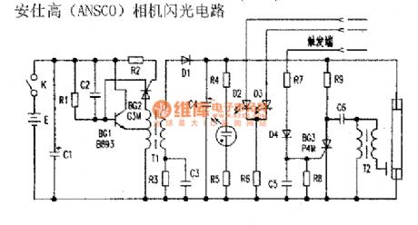
Ansco camera flash circuit
Published:2011/4/21 1:05:00 Author:Nicole | Keyword: Ansco, camera
View full Circuit Diagram | Comments | Reading(1363)
Rising Edge Triggered High-current Switch Composed of MIC5156-××
Published:2011/4/20 21:58:00 Author:TaoXi | Keyword: Rising Edge, Triggered High-current Switch
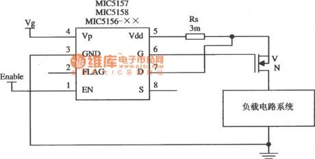
The Rising Edge Triggered High-current Switch Composed of MIC5156-×× (View)
View full Circuit Diagram | Comments | Reading(904)
3.3 V/lOA Output Linear Regulator Circuit Composed of MIC5157
Published:2011/4/21 2:31:00 Author:TaoXi | Keyword: 3.3V/lOA, Output Linear Regulator
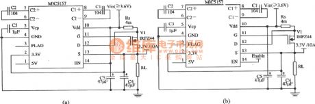
The 3.3 V/lOA Output Linear Regulator Circuit Composed of MIC5157
(View)
View full Circuit Diagram | Comments | Reading(896)
| Pages:116/126 At 20101102103104105106107108109110111112113114115116117118119120Under 20 |
Circuit Categories
power supply circuit
Amplifier Circuit
Basic Circuit
LED and Light Circuit
Sensor Circuit
Signal Processing
Electrical Equipment Circuit
Control Circuit
Remote Control Circuit
A/D-D/A Converter Circuit
Audio Circuit
Measuring and Test Circuit
Communication Circuit
Computer-Related Circuit
555 Circuit
Automotive Circuit
Repairing Circuit