
Electrical Equipment Circuit
Index 108
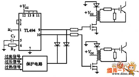
High power IGBT high frequency inverter electric welding machine circuit diagram
Published:2011/5/12 20:52:00 Author:Nicole | Keyword: IGBT, high frequency inverter, electric welding machine
View full Circuit Diagram | Comments | Reading(9407)
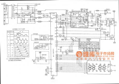
Panasonic NN-K652 computerized microwave circuit diagram
Published:2011/5/12 20:52:00 Author:Ecco | Keyword: Panasonic , computerized microwave
View full Circuit Diagram | Comments | Reading(2248)
LG elevator terminal switch and the outbound button pay-off circuit
Published:2011/5/12 18:58:00 Author:TaoXi | Keyword: LG elevator, terminal switch, outbound button, pay-off circuit
LG elevator terminal switch and the outbound button pay-off circuit (View)
View full Circuit Diagram | Comments | Reading(528)
TKJ-8201a elevator main circuit
Published:2011/5/12 18:58:00 Author:TaoXi | Keyword: elevator, main circuit
TKJ-8201a elevator main circuit (View)
View full Circuit Diagram | Comments | Reading(507)
LG elevator floor indicator circuit
Published:2011/5/12 18:55:00 Author:TaoXi | Keyword: LG elevator, floor indicator
LG elevator floor indicator circuit (View)
View full Circuit Diagram | Comments | Reading(567)
LG elevator outbound button and the indicator light circuit
Published:2011/5/12 18:52:00 Author:TaoXi | Keyword: LG elevator, outbound button, indicator light
LG elevator outbound button and the indicator light circuit (View)
View full Circuit Diagram | Comments | Reading(467)
LG elevator internal choice-button and the indicator light circuit
Published:2011/5/12 18:54:00 Author:TaoXi | Keyword: LG elevator, internal choice-button, indicator light
The LG elevator internal choice-button and the indicator light circuit (View)
View full Circuit Diagram | Comments | Reading(499)
SCR Circuit Driven By Trigger
Published:2011/5/12 9:31:00 Author:Robert | Keyword: SCR, Trigger
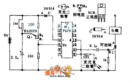
The unijunction transistor Q1 is used as the clock for the relaxation oscillator to drive one trigger of the 7473 double triggers. The output Q is used to trigger the SCR so that the power voltage can be chosen freely according to the application. But it can not exceed the rated voltage of SCR.
(View)
View full Circuit Diagram | Comments | Reading(917)
Wheat Seeder Particles Clogging Alarm Circuit
Published:2011/5/12 9:48:00 Author:Robert | Keyword: Wheat, Seeder, Particles, Clogging, Alarm
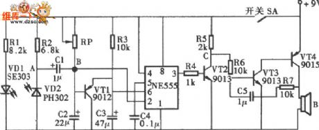
The wheat seeder particles clogging alarm circuit is shown below.
(View)
View full Circuit Diagram | Comments | Reading(569)
Infrared Detecting Voice Alarm Device Circuit
Published:2011/5/12 9:37:00 Author:Robert | Keyword: Infrared Detecting, Voice, Alarm
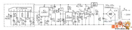
The Infrared Detecting Voice Alarm Device Circuit is shown below.
(View)
View full Circuit Diagram | Comments | Reading(553)
General Brand Cool Refrigerator With Frozen Food Room And Ice-Making Room Circuit
Published:2011/5/12 19:54:00 Author:Robert | Keyword: General Brand, Cool Refrigerator, Frozen Food Room, Ice-Making Room
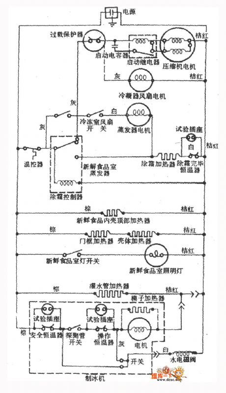
The General Brand Cool Refrigerator With Frozen Food Room And Ice-Making Room Circuit is shown below.
(View)
View full Circuit Diagram | Comments | Reading(859)
A KV Protection Circuit
Published:2011/5/12 9:59:00 Author:Robert | Keyword: KV Protection
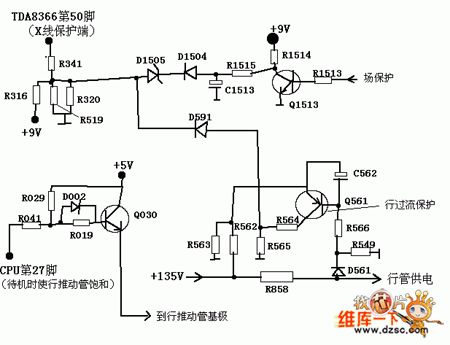
A KV Protection Circuit is shown below.
(View)
View full Circuit Diagram | Comments | Reading(533)
Summer Air Conditioner Working Principle Circuit
Published:2011/5/12 10:00:00 Author:Robert | Keyword: Summer, Air Conditioner, Working Principle
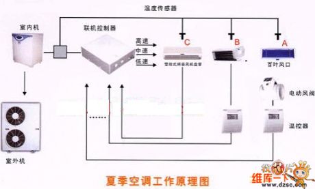
The Summer Air Conditioner Working Principle Circuit is shown below.
(View)
View full Circuit Diagram | Comments | Reading(1250)
Illumination Intensity Meter Circuit
Published:2011/5/12 9:54:00 Author:Robert | Keyword: Illumination Intensity, Meter
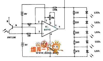
The Illumination Intensity Meter Circuit is shown below.
(View)
View full Circuit Diagram | Comments | Reading(682)
New phone line protection circuit diagram
Published:2011/5/8 5:47:00 Author:Rebekka | Keyword: New phone line protection
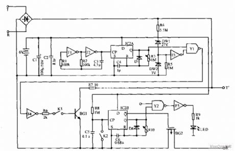
New phone line protection circuit is shown as below. Telephone wiring in the T and R ends. When someone steal the outside line. BG1 will be conducted. The voltage between T and R is only 2V. The protection will reset automatically after hanging up. When you are calling, press K. If the LED does not light means there is eavesdropping; If the LED lights, it shows that lines are not tapped. (View)
View full Circuit Diagram | Comments | Reading(1489)
The predetermined analog timer circuit diagram
Published:2011/5/8 7:36:00 Author:Rebekka | Keyword: analog timer
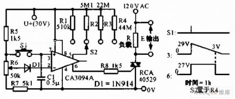
The predetermined analog timer circuit diagram is shown as below. It uses programmable power switch CA3094 to constitute the predetermined analog timer. The circuit gives four kinds of delay selection. It uses potentiometer R6 to set the initial time. When S2 connects to R4, click S1, the triac can work for 1 hour. (View)
View full Circuit Diagram | Comments | Reading(1114)
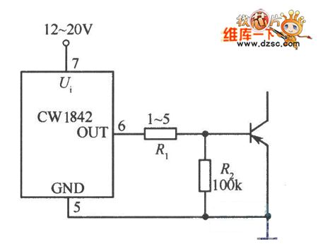
Using CS1842 To Drive Directly Bipolar Power Transistor Circuit
Published:2011/5/11 23:06:00 Author:Robert | Keyword: Bipolar Power Transistor
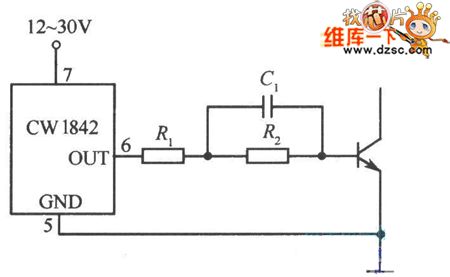
The Using CS1842To Drive Directly Bipolar Power Transistor Circuit is shown below.
(View)
View full Circuit Diagram | Comments | Reading(524)
Using CS1842 To Drive Directly M06 Transistor Circuit
Published:2011/5/11 23:07:00 Author:Robert | Keyword: M06 Transistor
The Using CS1842 To Drive Directly M06 Transistor Circuit is shown below.
(View)
View full Circuit Diagram | Comments | Reading(636)
Using CW1525A To Drive Bipolar Transistor Half-Bridge Circuit
Published:2011/5/11 23:07:00 Author:Robert | Keyword: Bipolar Transistor, Half-Bridge
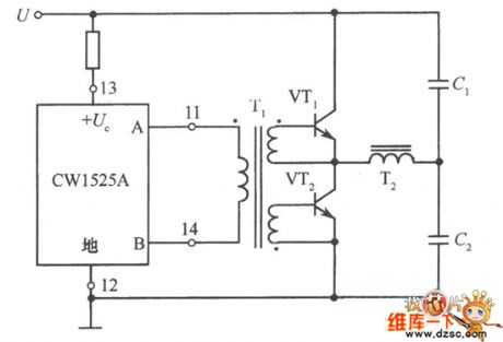
The Using CW1525A To Drive Bipolar Transistor Half-Bridge Circuit is shown below.
(View)
View full Circuit Diagram | Comments | Reading(1235)
The simplest radio circuit
Published:2011/5/11 7:23:00 Author:Christina | Keyword: simplest, radio circuit
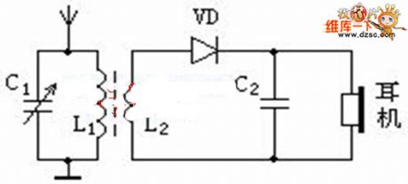
The The simplest radio circuit is as shown:
The tuning circuit is composed of the L1 and C1, the wave-detection circuit is composed of the VD and C2, the coupling circuit is composed of the L1 and L2.
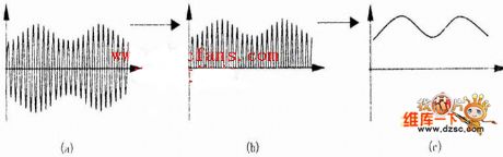
Signal waveform of the before-detection and after-detection:
The advantages and disadvantages of the direct broadcast type radio:
The advantages: the circuit is simple, small-size, low cost, easy to carry and easy to make.
The disadvantages: the sensitivity is low, poor selection.
The advantages and disadvantages of the heterodyne type radio:
The advantages: the sensitivity is high, good selection.
The disadvantages: the circuit is complex, high cost, hard to make. (View)
View full Circuit Diagram | Comments | Reading(637)
| Pages:108/126 At 20101102103104105106107108109110111112113114115116117118119120Under 20 |
Circuit Categories
power supply circuit
Amplifier Circuit
Basic Circuit
LED and Light Circuit
Sensor Circuit
Signal Processing
Electrical Equipment Circuit
Control Circuit
Remote Control Circuit
A/D-D/A Converter Circuit
Audio Circuit
Measuring and Test Circuit
Communication Circuit
Computer-Related Circuit
555 Circuit
Automotive Circuit
Repairing Circuit