
Electrical Equipment Circuit
Index 102
Fan Circuit
Published:2011/5/20 9:44:00 Author:Robert | Keyword: Fan
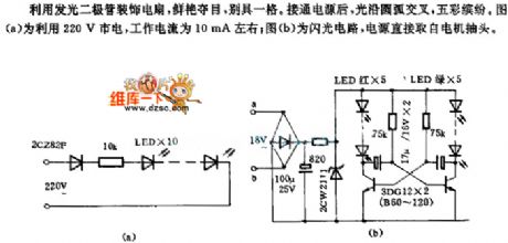
The fan circuit is shown below. Using the LED to decorate the fan, itwould becolorful, unique. When the power is connected, the light would cross along the arc. The picture (a) uses 220V commercial power and its working current would be about 10mA. The picture (b) is flash light circuit and the power is directly from the electric motor connector end.
(View)
View full Circuit Diagram | Comments | Reading(551)
Reducing Power Consumption ISO113 Circuit
Published:2011/5/21 1:56:00 Author:Robert | Keyword: Reducing, Power Consumption
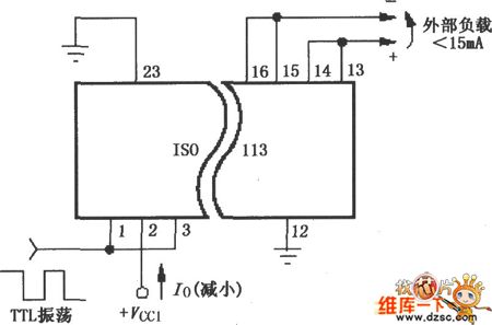
The Reducing Power Consumption ISO113 Circuit is shown in the picture shown below. For single-channel or multi-channel synchronization application it requires the Vcc1's current to be less than +/-15mA. It can use a oscillation circuit to generator TTL voltage level to drive the synchronization input port(3 foot) and enable port (1 foot) to reduce the power consumption.
(View)
View full Circuit Diagram | Comments | Reading(690)
TTS-200 Series Temperature-Control Thyristor Basic Application Circuit
Published:2011/5/21 20:25:00 Author:Robert | Keyword: Temperature-Control, Thyristor, Application
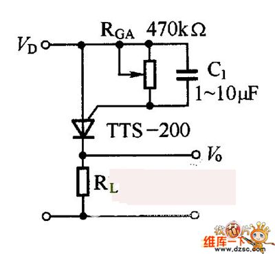
The temperature-control thyristor basic application circuit is shown in the picture below. RcA is the resistance to control the switch temperature. With different value of RcA it can get different switch temperature. The VD is working voltage. When the temperature is lower than the switch temperature, the temperature-control thyristor is disconnected and the Vo port outputs low voltage level. When the temperature is equal or higher than the switch temperature, the temperature-control thyristor is connected and Vo port outputs high voltage level. It should note that, the working voltage VD also has relations with switch temperature. To assure the stability of the switch temperature, VD should be taken measures of regulating voltage. C is a capacitor to prevent the disturbance.
(View)
View full Circuit Diagram | Comments | Reading(738)
Electric Energy Metering System Simplified (Single-Phase Electric Energy Metering System AD7551) Circuit
Published:2011/5/21 1:39:00 Author:Robert | Keyword: Electric Energy, Metering System, Single-Phase
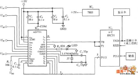
The electric energy metering system simplified circuit is shown in the picture below which is made up by AD7551 and the 89C51 MCU. C1~C4 are +5V power decoupling capacitor. The R-nor port is connected with the UDD through a pull-up resistance R1 to make the R-nor port be 1 and the reset port disabled. The 3.679545MHz crystal and capacitor C5, C6 are made up oscillation circuit to provide the timing signals to AD7751. C7 is the denoising capacitor of Uref(i/o) port.
(View)
View full Circuit Diagram | Comments | Reading(2705)
INA166 Input Stable Network Circuit
Published:2011/5/21 21:50:00 Author:Robert | Keyword: Input, Stable, Network
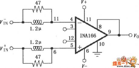
The INA166 Input Stable Network Circuit is shown in the picture below. A very low signal source's resistance (lower than 10Ω) can cause the INA166 to have self-oscillation. By adding two small inductance and small resistance at its input port it can make up a neywork which can minimize the self-oscillation trend. Althrough in INA166's other typical applications there is no inductance and resistance network, it can be added the inductance and resistance network to limit the self-oscillation when it is needed.
(View)
View full Circuit Diagram | Comments | Reading(604)
Rectifier Circuit
Published:2011/5/21 1:11:00 Author:Robert | Keyword: Rectifier
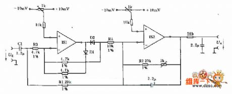
This circuit can change the input AC signals to DC signals. If the input signal has a low frequency, the capacitance C1 in input port can be cancelled.
In the negative half cycle, the operational amplifier IS1's output signals are connected through diode D1 (withcut-off voltage 0.7V) and would be isolated from the adding point through the diode D2. The operational amplifier IS2 isworking as out-phase voltage follower device.
In the positive half cycle, the IS1 isworking as out-phase amplifier and is connected to the adding point through R2. In input port, theresistance R3 and the resistanceR2 are made up a negative feedback loop circuit.
(View)
View full Circuit Diagram | Comments | Reading(563)
Bell of the Bicycle (the 2nd)
Published:2011/5/20 1:42:00 Author:Felicity | Keyword: Bell of the Bicycle (the 2nd)
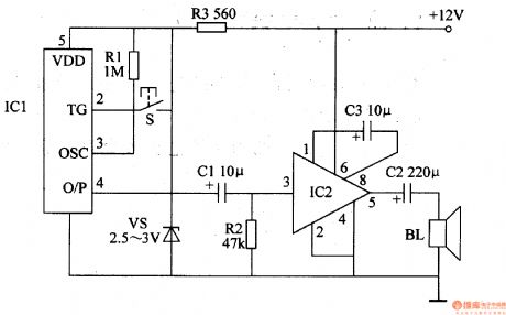
Work of the circuit
The circuit consists of voice circuit and voice-frequency amplifying circuit (It is showed in picture 7-168.).
The +12V voltage which comes from storage battery separates into two parts. One of them supplies working power to IC2 while the other one supplies 3V DC voltage to IC1.
Press button S IC1 begins to work and voice signal is outputted from its O/P. The signal drives BL make the voice “Please give way, thank you” after being amplified. (View)
View full Circuit Diagram | Comments | Reading(621)
sensor transmission principle circuit
Published:2011/5/23 22:04:00 Author:John | Keyword: sensor transmission
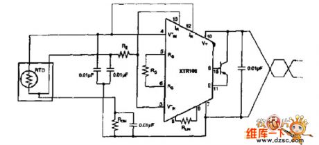
RTD input connects the bypass capacitor to reduce or eliminate interference. The capacitor is connected to the pipe end 7. If the DC voltage on pin 7 is not zero, it can be considered that the pin 7 is terminated to the ground.
(View)
View full Circuit Diagram | Comments | Reading(586)
The MC3362 Low-Power Narrow-Band FM Receiver Integrated Circuit Typical Application Circuit
Published:2011/5/21 20:00:00 Author:Robert | Keyword: Low-Power, Narrow-Band, FM, Receiver, Integrated, Application
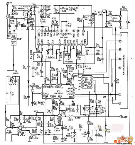
The MC3362 is produced by Motorola which is a low-power narrow-band FM receiver integrated circuit. It is widely used in narrow-band voice and data communications in the FM receiver circuits. The MC3362 integrated circuit has two FM transformation oscillators, mixers etc. which means it has a complete FM narrow-band receiver circuit. The decoder typical application's circuit composed of MC3362 integrated circuit is shown in the pocture below.
(View)
View full Circuit Diagram | Comments | Reading(4560)
Low-Frequency Modulator Circuit
Published:2011/5/21 8:17:00 Author:Robert | Keyword: Low-Frequency, Modulator
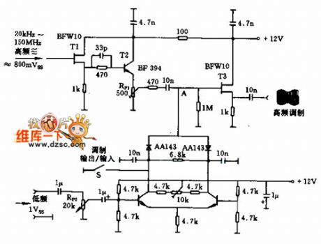
This circuit is a amplitude modulator circuit. The T1 and T2 transistors are used to separate the modulator part. The low-frequency signal has the best value when the potentiometer RP1 is adjusted to about 500mV. The low-frequency then passes the isolation stage T3 which would output low-frequency modulation signals. The low-frequency amplitude is adjusted by the potentiometer RP2.
(View)
View full Circuit Diagram | Comments | Reading(689)
The instrument and warning indicator circuit of VOLCANE
Published:2011/5/19 20:52:00 Author:Borg | Keyword: warning indicator, VOLCANE
The instrument board of VOLCANE is divided into water thermometer(j) (with alarm lamp), engine rotating meter(k), oil pressure meter(P), fuel meter(i), speedometer(c) (with a big and small one), clock(L) and engine oil meter(O). Under the instrument board, there is a line of alarm lamps and indicators(with recognition figures), they are listed in the following.Left and right indicator(g,h) charging indicator(b) width/tail lamps(d) choke indicator(r)Low beam light(e) engine oil level indicator(m)
(View)
View full Circuit Diagram | Comments | Reading(766)
Electronic QN circuit diagram 4
Published:2011/5/26 4:25:00 Author:Lucas | Keyword: Electronic QN
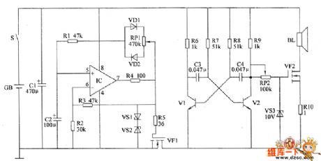
The electronic QN circuit is composed of the rectangular wave generator, electronic switching circuit, self-excited multivibrator and audio driver amplifier circuit, the circuit is shown as the chart. Rectangular wave generator circuit consists of operational amplifier integrated circuit IC, resistors R1 ~ R4, potentiometer RP1, diodes VD1, VD2, voltage regulator diode sVS1, VS2 and capacitor C2. Electronic switch circuit is composed of the field-effect transistor VF1, resistor R5 and VS1, VS2. Self-excited multivibrator by the transistors V1, V2, resistors R6 ~ R9 and capacitors C3, C4 composition. Audio driver amplifier consists of potentiometer RP2, voltage regulator diode VS3, resistor R1O, field-effect transistor VF2 and speaker BL.
(View)
View full Circuit Diagram | Comments | Reading(660)
The electronic QN circuit diagram 2
Published:2011/5/26 4:36:00 Author:Lucas | Keyword: electronic QN

The electronic QN circuit is composed of the multi-vibrator circuit, step-up circuit, voltage regulator, low frequency oscillator and the magnet control circuit and other components, the circuit is shown as the chart. Multivibrator is composed of six NOT gate integrated circuit IC (D1 ~ D6) and D1, D2 and capacitor C1, resistor R1 which is inside of NOT gate circuit. Step-up circuit consists of the transistor V1, step-up transformer T, rectifier diode VD1, resistors R2, R3 and capacitors C2, C3 and so on. Regulator circuit consists of resistors R4 ~ R6 and zener diodes VS. Low-frequency oscillator circuit is composed of the D3 ~ D6 and resistor R7, capacitor C4, diode VD2 which is inside of NOT gate. Solenoid control circuit is composed of the transistor V2, the relay K, diode VD3 and solenoid YV.
(View)
View full Circuit Diagram | Comments | Reading(817)
Electronic QN circuit diagram 1
Published:2011/5/26 4:29:00 Author:Lucas | Keyword: Electronic QN
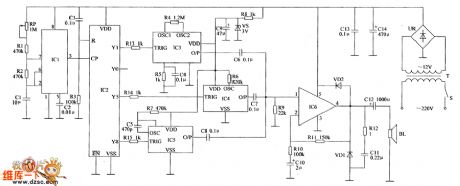
The electronic QN circuit is composed of the clock pulse generator, counter / pulse distributor, sound generator circuit, audio amplifier and power supply circuis and other components, the circuit is shown as the chart. Clock pulse generator circuit consists of time-base integrated circuit IC1 and self-excited multivibrator composed of the external RC components. Counter / pulse divider circuit consists of integrated circuit IC2 and resistor R3, capacitor C3. Sound generator circuit consists of Audio integrated circuits IC3 ~ IC5 and external RC components. Audio amplifier circuit consists of the power amplifier IC IC6, speaker BL, diodes VD1, VD2 and external RC components. Power circuit is composed of the power switch S, the power transformer T, rectifier bridge pile UR, filter capacitors C13, C14, C9, current limiting resistor R8 and Zener diode VS and so on.
(View)
View full Circuit Diagram | Comments | Reading(1036)
Agricultural automatic water supply device circuit diagram 5
Published:2011/5/21 11:18:00 Author:Lucas | Keyword: Agricultural , automatic , water supply device
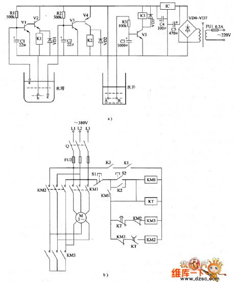
The agricultural automatic water supply device circuit is composed of supply circuit, water level measuring control circuit, water protection outage circuit and pump motor starter operation circuit, the circuit is shown in Figure 1. Power circuit is composed of fuse FU1, power transformer T, rectifier diodes VD4 ~ VD7, filter capacitors C4, C5, and three-terminal voltage regulator integrated circuit IC. Water level measuring control circuit consists of water level detection electrodes a ~ c, resistors R1, R2, capacitors C1, C2, transistors V1 ~ V4, diodes VD1, VD2 and relays K1, k2. Water protection outage circuit is composed of the detection electrodes A, B, resistor R3, capacitor C3, transistor V5, composed of diodes VD3 and relay K3. Pump motor starter operation circuit is composed of knife switch Q, fuse FU2, control buttons S1, S2, AC contactor KM1 ~ KM3, time relay KT and pump motor M. AC 220V voltage is bucked by T, rectified by VD4 ~ VD7 , filtered by C5 and stabilized by IC to provide +12 V voltage for the water level measuring control circuit and water protection outage circuit.
(View)
View full Circuit Diagram | Comments | Reading(2047)
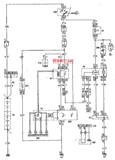
The light and signal wiring circuit of DPCA-VOLCANE DC7140 ZX(1)
Published:2011/5/19 20:21:00 Author:Borg | Keyword: wiring circuit, DPCA-VOLCANE
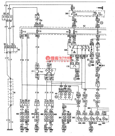
The light switch(211) is not on at the 0 gear, the license lights(391,392), left-head right-head position lamps(422,493, width lamp), left-rear right-rear lamps(496,497), and position indicator, which are under F13 and F12, are got through at 1 gear.
20-loudspeaker; 35-battery; 40-instrument board; 50-power supply box; 52-inscribed fuse box; 62-ground connection box; 130-alarm for light not-off; 170-steering flash; 391,392-left and right license lamp; 480,481-left and right tail lamp; 482-485-left-head, right-head, right-rear and left-rear fog lamp; 587,588-head and rear fog switch. (View)
View full Circuit Diagram | Comments | Reading(589)
INA166 Adding Output Current Buffer Circuit
Published:2011/5/21 21:55:00 Author:Robert | Keyword: Output Current, Buffer
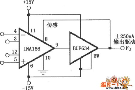
The INA166 Adding Output Current Buffer Circuit is shown in the picture below. It is added BUF634 at the INA166's output port to connect the wide bandwidth. BUF623 is B-B company's 250mA high-speed buffer to extend the output current. INA166's output voltage detecting port Sense should be connected to the output port of BUF634 to detect the output voltage Vo precisely.
(View)
View full Circuit Diagram | Comments | Reading(1329)
INA217 Low-Noise Low-Distortion Instrument Amplifier Pin Circuit
Published:2011/5/22 0:38:00 Author:Robert | Keyword: Low-Noise, Low-Distortion, Instrument, Amplifier, Pin
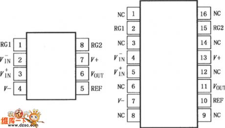
The INA217 is a low-noise, low distortion monolithic instrumentation amplifier. With its design of current feedback circuit it can be used in low voltage level audio signals' amplification such as symmetric low-resistance miniature microphone (microphone) signal amplification. INA217 has low noise and wide bandwidth. So it can be used in many industrial, instrumentation and medical applications. Its special distortion elimination circuit can minimize the distortion. With 200Ω source impedance the INA217 provides the low-noise performance which almost closing to the theoretical value.With the excellent performance ofdifferential input, low noise and low distortion, it provides professional miniature microphone (mike) signal amplification.
(View)
View full Circuit Diagram | Comments | Reading(1299)
INA217 Input Stable Network Circuit
Published:2011/5/22 0:42:00 Author:Robert | Keyword: Input, Stable Network
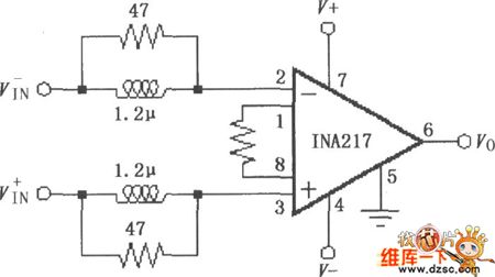
The INA217 Input Stable Network Circuit is shown in the picture below. A very low signal-source internal resistance (less than 10Ω) can cause the INA217 to have self-oscillation. If two small inductances and small resistances are added in the input port to make up a network, it can minimize the self-oscillation's trend. If needed, it can add the inductance and resistance network to limit its self-oscillation.
(View)
View full Circuit Diagram | Comments | Reading(1495)
Low-Drift Constant Current Source Circuit Composed Of MIC2951
Published:2011/5/22 2:04:00 Author:Robert | Keyword: Low-Drift, Constant Current Source
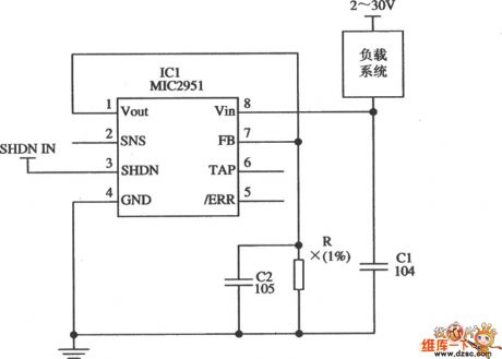
The Low-Drift Constant Current Source Circuit Composed Of MIC2951 is shown in the picture below. Its constant current source's output current is: IL=1.23V/R. In this formula, the value of R should not make the MIC2951's output current exceed 150mA. The accuracy of R is required as the principle of 1%.
(View)
View full Circuit Diagram | Comments | Reading(1252)
| Pages:102/126 At 20101102103104105106107108109110111112113114115116117118119120Under 20 |
Circuit Categories
power supply circuit
Amplifier Circuit
Basic Circuit
LED and Light Circuit
Sensor Circuit
Signal Processing
Electrical Equipment Circuit
Control Circuit
Remote Control Circuit
A/D-D/A Converter Circuit
Audio Circuit
Measuring and Test Circuit
Communication Circuit
Computer-Related Circuit
555 Circuit
Automotive Circuit
Repairing Circuit