
Remote Control Circuit
Index 23
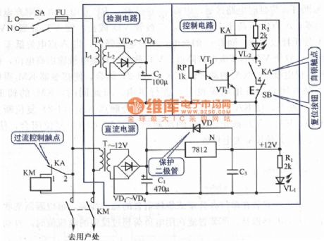
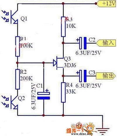
The auto power limiting circuit of PNP
Published:2011/6/2 3:16:00 Author:Seven | Keyword: power limiting circuit, PNP
View full Circuit Diagram | Comments | Reading(756)
TC9012F--the remote control emitter integrated circuit
Published:2011/6/7 10:56:00 Author:qqtang | Keyword: remote control, integrated circuit
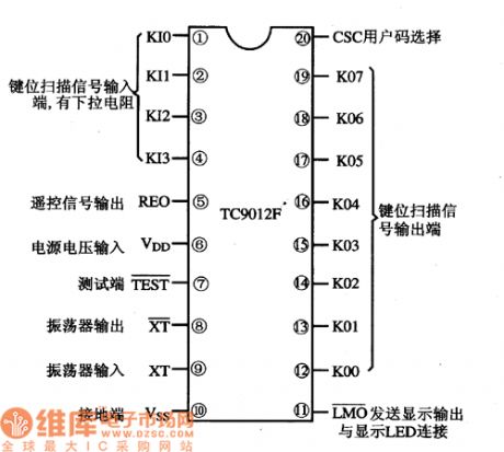
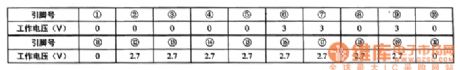
TC9012F is a remote control emitter integrated circuit produced by Toshiba, which is widely used in remote emitters of air-conditioners, TV sets, stereo equipment, disc players, etc.1.functions featuresTC9012F contains the key pulse generating circuit, key order encoding circuit, clock oscillating circuit, display drive circuit, customer number setting selector circuit, buffer amplifier circuit, test circuit and other additional function circuits.2.pin functions and dataTC9012F is in 20-pin dual line package.
(View)
View full Circuit Diagram | Comments | Reading(822)
TC9028AF-023--the integrated circuit of the remote emitter
Published:2011/6/7 1:43:00 Author:qqtang | Keyword: integrated circuit, remote emitter
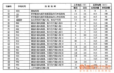
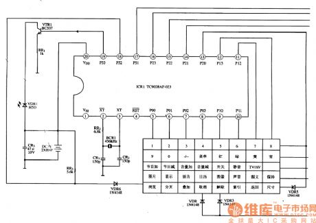
TC9028AF-023 is the integrated circuit of the remote emitter produced by Toshiba, which is widely used in the remote control system of large screen color TV.1.function featuresTC9028AF-023 contains clock oscillator circuit, reset circuit, key scanning encode circuit and other additional circuit.2.pin functions and dataTC9028AF-023 is in 20-pin dual line plastic package, whose pin functions and data are listed in Table 1.Notes:in the 2-pin and 3-pin of TC9028AF-023, the oscillator circuit and the external pottery resonator form a clock oscillator circuit.
(View)
View full Circuit Diagram | Comments | Reading(818)
General infrared remote control switch
Published:2011/6/1 20:48:00 Author:Christina | Keyword: General, infrared, remote control

Working principle: the infrared remote control switch circuit is as shown in the figure. It is composed of the infrared receiving module, the triode VQ1, the D flip-flop, the driving triode VQ3, the relay, the relay working status indicator LED, the ZD1 voltage-regulator diode and the triode VQ2.etc. The infrared receiving module of the circuit detects the remote launch 37.9kHz negative pulse sequence, there negative pulses change into the positive pulses by VQ1. Then these positive pulses change into the single pulses by the R4, VD1, R5 and C2 network. The positive pulses of the VQ1 collecting electrode charge the C2 through R4 and VD1. The charging time constant (R4 X C2) is about 1.25ms. (View)
View full Circuit Diagram | Comments | Reading(1110)
Optical electronic potentiometer circuit
Published:2011/5/20 5:36:00 Author:chopper | Keyword: Optical electronic, potentiometer
View full Circuit Diagram | Comments | Reading(2138)
TV remote controller 02
Published:2011/5/19 8:14:00 Author:TaoXi | Keyword: TV, remote controller
TV remote controller 02 (View)
View full Circuit Diagram | Comments | Reading(709)
TV remote controller 10
Published:2011/5/19 8:11:00 Author:TaoXi | Keyword: TV, remote controller
TV remote controller 10 (View)
View full Circuit Diagram | Comments | Reading(654)
TV remote controller 11
Published:2011/5/19 8:11:00 Author:TaoXi | Keyword: TV, remote controller
TV remote controller 11 (View)
View full Circuit Diagram | Comments | Reading(597)
Roll-pattern type wireless remote control circuits TH150/TH150A/TH150B
Published:2011/5/12 3:17:00 Author:TaoXi | Keyword: Roll-pattern, wireless remote control
The internal structure of the roll-pattern type wireless remote control circuit is very complex, the coding method is also very special, but the usage of this circuit is the same as the digital coding circuit, even more simple. The radio control circuit which is composed of the rolling code decoding circuits TH150/TH151A/TH151B. The radio transmission circuit (which is composed of the rolling code circuit, the TH150 and the transistor carrier frequency oscillator): The super-regenerative wireless remote control receiver circuit (which is composed of the TH151A/B rolling decoding circuit): (View)
View full Circuit Diagram | Comments | Reading(618)
Remote control transmitter circuit composed of the TX4915
Published:2011/5/12 1:05:00 Author:TaoXi | Keyword: Remote control transmitter
Remote control transmitter circuit is composed of the TX4915. (View)
View full Circuit Diagram | Comments | Reading(643)
Infrared remote control music socket circuit 2 PH303A
Published:2011/5/12 6:50:00 Author:TaoXi | Keyword: Infrared remote control, music socket circuit
The PH303A×2 infrared pulse transmitter circuit is as shown, by adjusting the RP1 you can make the oscillation frequency to12kHz.
Infrared remote control receiver circuit: (View)
View full Circuit Diagram | Comments | Reading(603)
Temperature adjustment quantity resistance-frequency converter circuit
Published:2011/5/20 7:11:00 Author:TaoXi | Keyword: Temperature adjustment, quantity, resistance, frequency, converter circuit
Temperature adjustment quantity resistance-frequency converter circuit (View)
View full Circuit Diagram | Comments | Reading(633)
TV remote controller 01
Published:2011/5/19 8:15:00 Author:TaoXi | Keyword: TV, remote controller
TV remote controller 01 (View)
View full Circuit Diagram | Comments | Reading(597)
The temperature test circuit of thermistors
Published:2011/5/19 23:59:00 Author:Borg | Keyword: test circuit, thermistors
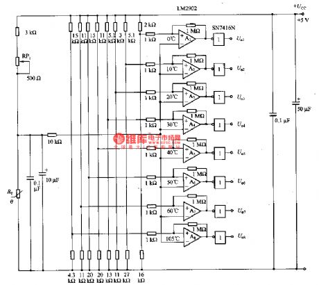
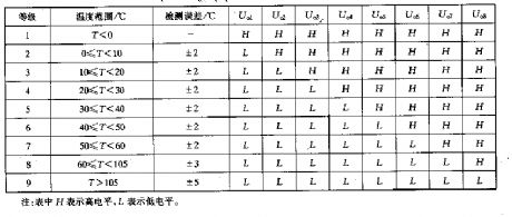
The figure is a temperature test circuit with thermistors. In the circuit, thermistors are used as the temperature sensor RT, the testing temperature is divided into 9 levels. By using comparators of Al一A8, the output high-low LEV represents the tested temperature. The relationships between LEV output by U.I-U.8 and temperature are listed in the table. (View)
View full Circuit Diagram | Comments | Reading(836)
TV remote controller 04
Published:2011/5/19 8:14:00 Author:TaoXi | Keyword: TV, remote controller
TV remote controller 04 (View)
View full Circuit Diagram | Comments | Reading(616)
TV remote controller 06
Published:2011/5/19 8:13:00 Author:TaoXi | Keyword: TV, remote controller
TV remote controller 06 (View)
View full Circuit Diagram | Comments | Reading(607)
TV remote controller 09
Published:2011/5/19 8:12:00 Author:TaoXi | Keyword: TV, remote controller
TV remote controller 09 (View)
View full Circuit Diagram | Comments | Reading(642)
TV remote controller 18
Published:2011/5/19 8:05:00 Author:TaoXi | Keyword: TV, remote controller
TV remote controller 18 (View)
View full Circuit Diagram | Comments | Reading(639)
TV remote controller 17
Published:2011/5/19 8:05:00 Author:TaoXi | Keyword: TV, remote controller
TV remote controller 17 (View)
View full Circuit Diagram | Comments | Reading(623)
TV remote controller 16
Published:2011/5/19 8:08:00 Author:TaoXi | Keyword: TV, remote controller
TV remote controller 16 (View)
View full Circuit Diagram | Comments | Reading(598)
| Pages:23/34 At 202122232425262728293031323334 |
Circuit Categories
power supply circuit
Amplifier Circuit
Basic Circuit
LED and Light Circuit
Sensor Circuit
Signal Processing
Electrical Equipment Circuit
Control Circuit
Remote Control Circuit
A/D-D/A Converter Circuit
Audio Circuit
Measuring and Test Circuit
Communication Circuit
Computer-Related Circuit
555 Circuit
Automotive Circuit
Repairing Circuit