
Remote Control Circuit
Index 22
4-hour AC Power Supply Timer Circuit
Published:2011/5/18 9:39:00 Author:Joyce | Keyword: 4-hour, AC Power Supply , Timer

As shown in the figure is a 4-hour AC power supply timer circuit. In this circuit, BH4024 is a 7-level binary system counter/frequency divider, and 555 is a timebase circuit. AN is a timing touch button. Everytime you press AN once, it could output four-hour 220V AC power supply, after 4 hours,it will outage. This circuit can be used in working time whose morning and afternoon is separated by4-hour as an unit.
(View)
View full Circuit Diagram | Comments | Reading(2021)
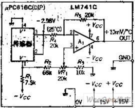
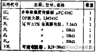
Can be linear output 10MV / ° C voltage IC temperature conversion circuit
Published:2011/6/2 4:26:00 Author:Fiona | Keyword: linear output, temperature conversion
Circuit Work
The IC internal temperature sensor can obtain the voltage output which is proportional with 10MV/°K.The lead 2,3 of the internal amplifier play the role of buffer after connectings.It can make the output voltage is zero power at any temperature whenusing the level shift circuit A1.The lead 1,4 of the sensor internal have 6.85V zener diode ,obtain 1MA ~ 5MA home bias current from R1.Reference voltage inputs from the R2, which is obtained by variable resistor VR1 partial pressure.
(View)
View full Circuit Diagram | Comments | Reading(867)
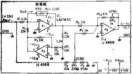
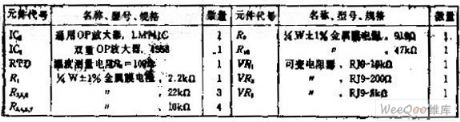
simplified resistance temperature circuit that improving the linear by using positive feedback
Published:2011/5/13 2:57:00 Author:Fiona | Keyword: improving the linear by using positive feedback
Circuit function
This circuit is a temperature measurement which uses a positive feedback way and has a linearizer,if temperature rises, the current flows through RTD will increase,if the temperature range is 0 ~ 500 ° C, we can obtain 0 ~ 5V of Voltage output, the error can be controlled within plus or minus 0.08%. Circuit Work OP amplifier A1is the inverting amplifier, it connects with RTD in the feedback loop, when set side the constant current with 5MA currents, A1 output may have-0.5V voltage. Assume that the RTD's variation is △ R,the output voltage's variation is △ R * 5MA. (View)
View full Circuit Diagram | Comments | Reading(729)
TV remote controller 08
Published:2011/6/9 3:05:00 Author:TaoXi | Keyword: TV, remote controller
TV remote controller 08
(View)
View full Circuit Diagram | Comments | Reading(617)
TV remote controller 07
Published:2011/6/9 3:05:00 Author:TaoXi | Keyword: TV, remote controller
TV remote controller 07
(View)
View full Circuit Diagram | Comments | Reading(634)
A digital clock standard 60HZ time-based circuit
Published:2011/6/8 7:10:00 Author:Fiona | Keyword: A digital clock standard 60HZ time-based
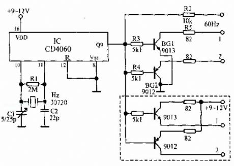
CD4060 is a 14-bit binary serial counter / oscillator frequency divider. Oscillator and External crystal R1, C1, C2 constitute the 30720Hz oscillator circuit; another part is the 14 frequency divider. Use the former 9 levels divider, and its frequency is 512.The standard 60Hz signal obtained by the oscillator output through the frequency division output from the Q9, as the standard base signal of the digital clock circuit. BG1, BG2 constitute a 60Hz signal synchro switch, Under the effect of 60Hz signal, BG1, BG2 conduct alternately, BG1 collector and BG2 emitter respectively connected todouble-negative-type display 1 and and 2 feets, ensure that the double-negative-type display works properly.
(View)
View full Circuit Diagram | Comments | Reading(3050)
TV remote controller 03
Published:2011/6/9 3:06:00 Author:TaoXi | Keyword: TV, remote controller
TV remote controller 03
(View)
View full Circuit Diagram | Comments | Reading(753)
Dual-watch controlled SCR timer circuit (3)
Published:2011/5/19 0:41:00 Author:TaoXi | Keyword: Dual-watch, SCR, timer circuit
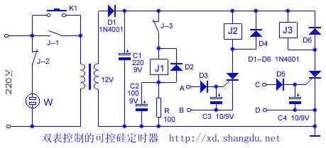
Working principle: the circuit is as shown. When you press the K1, the power supply will be changed into the 6V DC after the proess of step-down, rectify and filtering. At this time, the power NC contact point J-3 makes J1 to work, and J1's normally open contact point J1-1 closes, the circuit will lock itself. At this time if you release K1, the circuit is in the working condition because of the self-locking. When the timing boot audio signal is input from the two ends of A, B, this signal will be rectified and filtered by D3 and C3 to trigger the SCR1 and makes J2 to work, J2's normally open contact point J-2 closes, socket W has the electricity, the controlled appliances is connected. Similarly, when another electronic alarm clock's regular shutdown audio signal is input from C and D, this this signal will be rectified and filtered by D5 and C4 to trigger the SCR2 and makes J3 to work.
(View)
View full Circuit Diagram | Comments | Reading(1762)
Double-watch timer circuit (1)
Published:2011/5/17 21:40:00 Author:TaoXi | Keyword: Double-watch, timer circuit
Related components PDF download:
9013
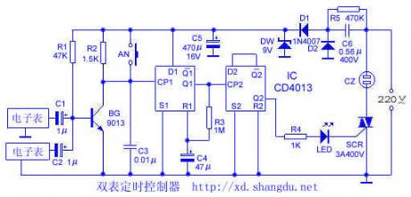
The circuit is as shown in the figure. This circuit uses two electronic wall watch with the alarm function, the signals is output from the both ends of piezoelectric ceramics. When the wall watch alarms, the signal gets to BG base port through C1 (or C2), and this signal is amplified to trigger the monostable circuit which is composed of the D flip-flop, Q1 outputs the high-level voltage and triggers the bistable circuit which is composed of the D flip-flop, Q2 outputs the high-level voltage and triggers the SCR to turn on; Meanwhile the LED lights, the Instruction timer is working. The monostable circuit's Q1 outputs the high-level voltage to charge C4 through R3, after a certain time, R1 has the high-level voltage to make Q1 to restore the low level. When the second watch alarm, the monostable circuit outputs a positive pulse to make the bistable circuit to output the low level voltage, so the LED turns off, the electrical equipments are out of electricity.
(View)
View full Circuit Diagram | Comments | Reading(928)
temperature control & closing protection circuit
Published:2011/5/11 2:05:00 Author:TaoXi | Keyword: temperature control, closing
Related component PDF download:
TCA965
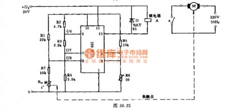
Many machines can only be running in a certain temperature range for the best and the most economical status. If the temperature exceeds a certain permissible operating temperature, the machine may be damaged or reduce its service life. So we can use the protection circuit. This circuit uses the thermistor RH as the sensor. In order to ensure that there is no direct electrical contact between the protection circuit and the equipment, we can use the relay control.
In the condition of trouble-free or given temperature, the machine is connected by the relay. Otherwise, the relay will release and the motor will cut off.
(View)
View full Circuit Diagram | Comments | Reading(964)
Infrared heating device temperature control circuit
Published:2011/5/18 10:31:00 Author:TaoXi | Keyword: Infrared, heating device, temperature control
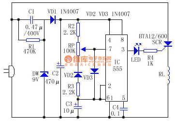
Working principle: the circuit is as shown, IC (555) connects to the low frequency oscillator, by adjusting RP, you can change C3's recharging time constant, and the pin-3's output pulse duty ratio also changes too, that changes the ratio of the SCR conduction and closing time, and also control the average power of the heating pipe RL to achieve the temperature control purpose.
When RP is adjusted to the top value, the IC output pulse duty ratio is about 0 , RL gets the minimum power; When RP is adjusted to the lowest value, the IC output pulse duty ratio is about 1 , RL gets the maximum power. So you can make the IC output pulse duty ratio continuous changes between 0 and 1 .
(View)
View full Circuit Diagram | Comments | Reading(1605)
The over-current protection circuit of thyristors
Published:2011/6/9 0:11:00 Author:Seven | Keyword: over-current protection circuit, thyristor
View full Circuit Diagram | Comments | Reading(741)
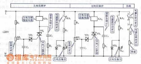
The transistor over/low-voltage protection circuit
Published:2011/6/9 0:12:00 Author:Seven | Keyword: over/low-voltage, protection circuit
View full Circuit Diagram | Comments | Reading(813)
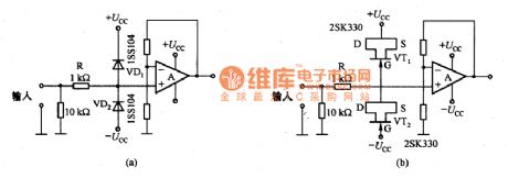
VOUT terminal protection circuit diagram
Published:2011/6/8 21:55:00 Author:Sophia | Keyword: VOUT terminal, Protection circuit
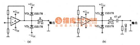
(View)
View full Circuit Diagram | Comments | Reading(811)
Input protection circuit of high input impedance circuit diagram
Published:2011/6/8 21:41:00 Author:Sophia | Keyword: High input impedance circuit, Input protection circuit
(View)
View full Circuit Diagram | Comments | Reading(773)
Wireless remote electronic detonating device circuit diagram 2
Published:2011/6/9 6:17:00 Author:Lucas | Keyword: Wireless remote , electronic , detonating device
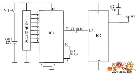
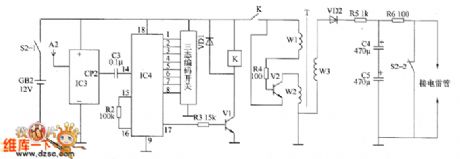
The wireless remote electronic detonating device is composed of the wireless remote transmitter circuit and wireless receiver initiator circuit. The wireless remote transmitter circuit is composed of control button S1, battery OBI, wireless encoding integrated circuit IC1, wireless transmitter integrated circuit IC2, resistor R1, capacitors U1, C2, transmitter antenna A1, and the circuit is shown as the chart. R1 ~ R4 select 1/4W metal film resistors; R5 and R6 select 1W metal film resistors. C1 and C3 select monolithic capacitors; C2 uses aluminium electrolytic capacitor with the voltage in 16V; C4 and C5 select electrolytic capacitor with the voltage in 630V. V1 chooses 58050 silicon NPN transistor; V2 uses BU406 high back pressure NPN silicon transistor.
(View)
View full Circuit Diagram | Comments | Reading(1467)
Wireless remote electronic detonating device circuit diagram 1
Published:2011/6/9 6:08:00 Author:Lucas | Keyword: Wireless remote , electronic , detonating device
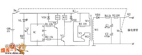
Wireless receiver initiator circuit is composed of the power circuit, wireless receiver control circuit, oscillation step-up circuit and charge-discharge circuit, and the circuit is shown as the chart. The power circuit consists of the battery GB, switch S (Sa, Sb), power indicator LED VL and current limiting resistor R6. Wireless receiver control circuit is composed of the wireless receiver module IC, resistors R1 and R2, transistors V1 and V2, relays K1 and K2 and diodes VD1, VD2. Oscillating boost circuit is composed of the normally open contact of K1, resistor R3, transistor V3, step-up transformer T and rectifier diode VD3. Charge-discharge circuit consists of resistors M and R5, capacitors C1 and C2, power switch Sb and the normally open contact of K2. R1 ~ R4 and R6 select 1/4W metal film resistors.
(View)
View full Circuit Diagram | Comments | Reading(923)
The detection circuit of Santana power control system components
Published:2011/5/14 4:00:00 Author:Borg | Keyword: detection circuit, Santana, power control system
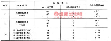
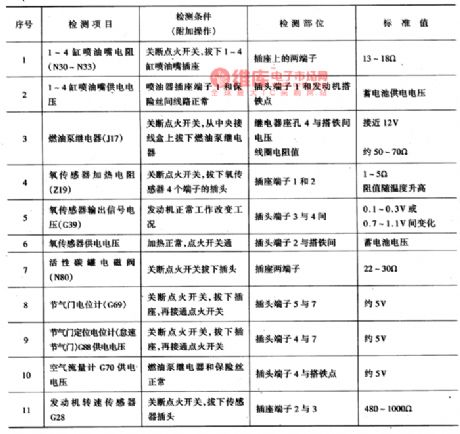
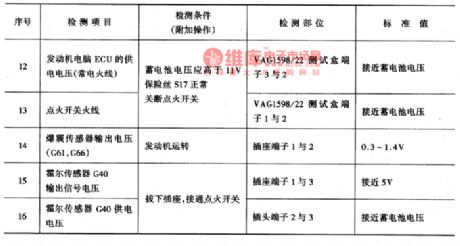

To detect if a component links to computer J220, we can refer to Figure 1 to Figure 6, the part between terminal of 80 connector and connector of sensor or executor is tested with ohm mode(with buzz) of multimeter; generally, if the connection is OK, i.e without disruption or eroding, the displayed number will be less than o.5Ω; even in the long circuit, the resistence is under 1Ω, and the buzzer will buzz if not. Figure 3 the disruption detection between AJR engine power-control ECU system and components
(View)
View full Circuit Diagram | Comments | Reading(928)
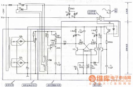
The electric timer circuit of ceiling fans
Published:2011/6/4 6:53:00 Author:qqtang | Keyword: electric timer, ceiling fans
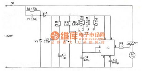
The timer circuit consists of the power supply circuit, time delay control circuit and single steady trigger control circuit, see as figure 1.
In the circuit, the power supply circuit consists of the power supply switch C1, releasing resistor R1, voltage steady diode VS, rectifier diode VD and filter capacitor C2; the time delay control circuit consists of the NPN V, resistors of R2 and R3 and the capacitor C3; the single steady trigger control circuit consists of timer selecting switch S2, capacitors of C4 and C5, the time-based integrated circuit IC, resistors of R4-R8 and thyristor VT. (View)
View full Circuit Diagram | Comments | Reading(1366)
The AC voltage regulation circuit of close-loop control
Published:2011/6/2 6:40:00 Author:Seven | Keyword: voltage regulation, close-loop control
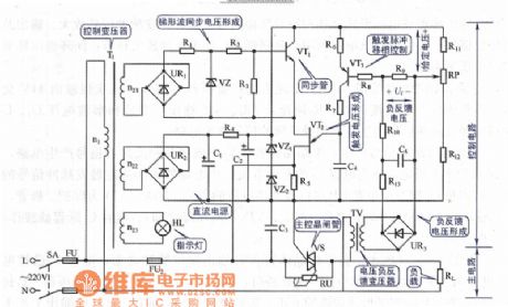
View full Circuit Diagram | Comments | Reading(955)
| Pages:22/34 At 202122232425262728293031323334 |
Circuit Categories
power supply circuit
Amplifier Circuit
Basic Circuit
LED and Light Circuit
Sensor Circuit
Signal Processing
Electrical Equipment Circuit
Control Circuit
Remote Control Circuit
A/D-D/A Converter Circuit
Audio Circuit
Measuring and Test Circuit
Communication Circuit
Computer-Related Circuit
555 Circuit
Automotive Circuit
Repairing Circuit