
Remote Control Circuit
Index 28
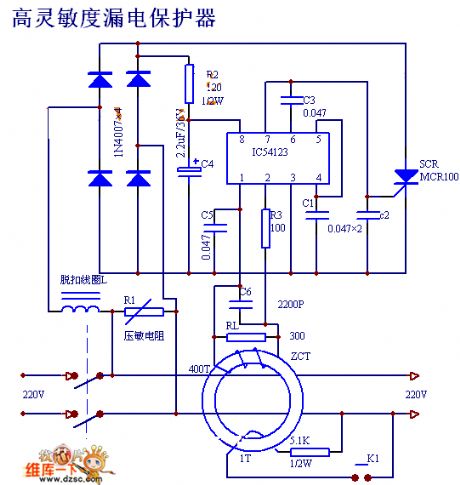
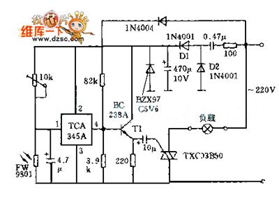
High Sensitivity Leakage Protection
Published:2011/5/3 5:13:00 Author:Felicity | Keyword: High Sensitivity Leakage Protection,
View full Circuit Diagram | Comments | Reading(945)
Actuation Delaying Relay Circuit
Published:2011/4/25 23:55:00 Author:Joyce | Keyword: Actuation Delaying, Relay
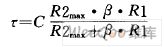
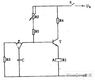
If a delay circuit which is long-lasting and easy to adjust is wanted , then the relay current should be controlled by the transistor, and a RC link should be connected to the basic circuit, as shown in the figure. If power supply voltage, capacitance C, current amplification factor β and the required operation power are known, you should choose the appropriate relay coil resistance and working voltage values, so that delay time could be as long as possible. The length of time can be determined by calculating the time constant :
(View)
View full Circuit Diagram | Comments | Reading(892)
United sound AV-2020 amplifier remote control circuit
Published:2011/4/23 2:01:00 Author:May | Keyword: United sound, amplifier, remote control
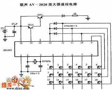
United sound AV-2020 amplifier remote control circuit is shown in the following picture:
(View)
View full Circuit Diagram | Comments | Reading(1360)
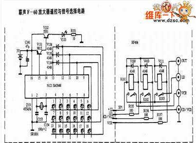
United Sound F-60 amplifier remote control and signal select circuit
Published:2011/4/2 4:12:00 Author:may | Keyword: United Sound amplifier, remote control and signal select
View full Circuit Diagram | Comments | Reading(972)
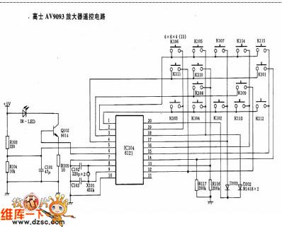
KONES AV9093 amplifier remote control circuit
Published:2011/4/2 4:16:00 Author:may | Keyword: KONES, amplifier, remote control
View full Circuit Diagram | Comments | Reading(1717)
Fan uses PTC devices to increase breeze gear circuit 2
Published:2011/4/11 2:48:00 Author:may | Keyword: Fan, PTC devices, breeze gear
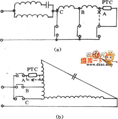
Fan uses PTC devices to increase breeze gear circuit is shown in the following diagram:
(View)
View full Circuit Diagram | Comments | Reading(759)
Using LM386 as photorelay circuit diagram
Published:2011/4/28 1:23:00 Author:Rebekka | Keyword: photorelay
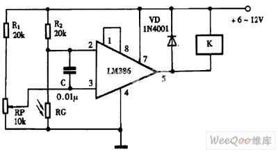
Using LM386 as photorelay circuit diagram is shown as above. (View)
View full Circuit Diagram | Comments | Reading(1544)
A Reliable Ultrasonic Remote Control Switch Circuit
Published:2011/4/27 18:37:00 Author:Christina | Keyword: Reliable, Ultrasonic Remote Control
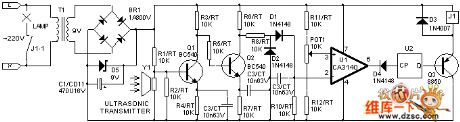
Transmitter circuit: u1 and external components form the multivibrator, after press the sw1, the output signal of u1(3) pin drive the ultrasonic transducer chip y1 by q1,q2 to sent out the ultrasonic signal.
Receiving circuit: in the standby mode, the electronic-level of u1(3) pin is higher than (2) pin, (6) pin sends out high electronic-level, trigger u2 holds the low output electronic-level, q3 cuts off, relay does not operate, so the lamp does not light; When the y1 received ultrasonic signal, after frequency selected amplification and rectification filtering, the signal get into the u1(2) pin, (6) pin becomes low electronic-level, trigger sends out high electronic-level, q3 connects and relay picks, the lamp is light as shown:
(View)
View full Circuit Diagram | Comments | Reading(1071)
Tape recorders remote volume control circuit composed of LC2200
Published:2011/4/22 1:18:00 Author:Rebekka | Keyword: Tape recorders remote volume control
LC2190/2200 remote encoding transmitter / receiver is improved LC219/220A ASIC. It has the decoding and error identification repeated comparisons, so you can effectively prevent the error action.
LC2190 shape pin map.
LC2200 shape pin map.
LC219 internal block diagram.
LC2200A internal block diagram.
Main electrical parametersThe work oscillation frequency of LC2190 transmitter chip is 80kHz; Input duty cycle is 1:1, f = 40kHz square wave pulse; Repetition rate between output pulse train is decided by the the capacitors of CT end. It usually is 3 ~ 5Hz; Operating voltage range is 2.5 ~ 3.5V, typical value is +3 V; Quiescent power supply current is less than 1μA. The output can drive the power transistor to gain the large emission current. LC2200 receiver chip supply voltage range is 3 ~ 9v, typical value is +5 V; Quiescent supply current is less than 5μV; Each output drive current IoH ≥ 2mA, 10L ≥ 1mA. It can directly drive NPN transistor, LED and low power SCR.
Infrared transmitter circuit composed of LC2190.
Continuous key turns to a single-button circuit.
Remote control circuit included in the volume composed of LC2200.
(View)
View full Circuit Diagram | Comments | Reading(825)
Low-cost thermal protection circuit diagram with adjustable temperature limit and programmable hysteresis voltage
Published:2011/4/26 4:09:00 Author:Rebekka | Keyword: adjustable temperature limit , programmable hysteresis voltage
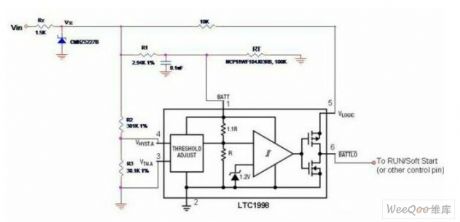
Thermal protection is very important in many power systems. Figure 1 shows a low-cost thermal protection circuit. LTC1998 is used for 6-pin battery monitoring SOT-23 package comparator. In this circuit it is used as heat protection. The thermal protection circuit can provide very useful features. Such as adjustable transition temperature, programmable hysteresis voltage and remote temperature sensing. When the detection point temperature rises. The voltage (Vbatt) of LTC1998 pin 1 will decline because of RT resistance. If Vbatt drops below 2.5V. The LTC1998 internal comparator transition changes, and Vbattlo (pin 6) turn to logic low. Pin 6 can be connected to the operation of the relevant power / soft-start (enable / shutdown) control side. Therefore, if the temperature rises to a pre-set trip point, you can turn off the power to prevent overheating.
(View)
View full Circuit Diagram | Comments | Reading(2148)
Circuit Of Remote Control Helicopter Driver Circuit
Published:2011/4/24 21:12:00 Author:Christina | Keyword: Remote Control Helicopter, Driver Circuit
The Circuit Of Remote Control Helicopter Driver Circuit is as shwon:
(View)
View full Circuit Diagram | Comments | Reading(5988)
Two-way SCR light control switch circuit
Published:2011/4/24 21:13:00 Author:Christina | Keyword: Two-way SCR, light control switch
The Two-way SCR light control switch circuit is as shwon:
(View)
View full Circuit Diagram | Comments | Reading(1640)
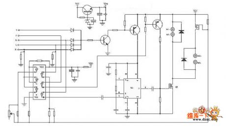
TC915OP remote control microprocessor integrated circuit
Published:2011/4/26 3:03:00 Author:TaoXi | Keyword: remote control, microprocessor
The TC915OP is one kind of remote control microprocessor which is designed to process the pulse from the remote control receiver, the pulse is decoded and transformed by the microprocessor to control each circuit, so this circuit is mainly used for a variety kinds of sound system.
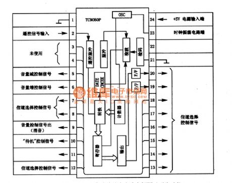
1. TC915OP circuit block diagram and pin functions
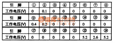
The TC915OP is composed of the remote control pulse discern circuit, check digit circuit, clock oscillation circuit, counter, register and output-drive circuit.etc. The circuit block diagram and pin functions is as shown in figure 1. The pin typical operating voltage is as shown in table 1.
Table 1. The pin typical operating voltage of TC9150P
Figure 1. TC915OP circuit block diagram and pin functions
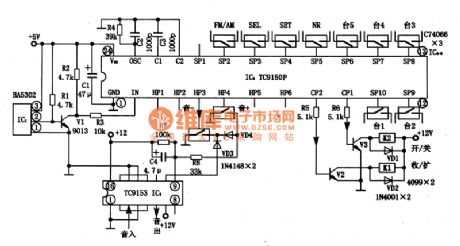
2. Typical application circuit of the TC915OP
The typical application circuit of the TC915OP is as shown. In circuit, IC1 can be used to receive the IR remote control signal, IC3 can be used to remote the volume. Remote control transmitter chip TC9153 can be assorted with the TC915OP.
Figure 2. Typical application circuit of the TC915OP
3. Theworking process of this circuit
4. Fault tips (View)
View full Circuit Diagram | Comments | Reading(3157)
Figure of the remote control transmitter IC TC9148P
Published:2011/4/26 7:39:00 Author:TaoXi | Keyword: remote control, transmitter

The TC9148P is one kind of remote control remote control transmitter IC that can be used with the microprocessor TC915OP, and this device can be use in variety of sound systems.
1. Pin functions of TC9148P
The TC9148P manifold circuit is composed of the clock oscillator circuit, the key instruction decoding and encoding circuit, the light driver circuit, remote control transmitter drive circuit.etc. The pin functions and pin arrangement of the TC9148P is as shown in figure 1, the operating voltage is as shown in table 1.
Figure 1. The pin functions and pin arrangement of the TC9148P
Table 1. Theoperatingvoltage of TC9148P
2.TC9148P typical application circuit
The TC9148P manifold's typical application circuit is as shown in figure 2.
Figure 2. The TC9148P manifold's typical application circuit
3.Circuit process
VTQ701 and VTQ702 is the output drive circuit of infrared light-emitting diode; LD701, LD702 are the infrared light-emitting diodes; the power supply back circuit is composed of the C702, R701, C701: X701 is the remote control transmitter crystal clock oscillator, the clock oscillation circuit is composed of this oscillator, the C703, C704 and the circuit in pin-2 & pin-3 of TC9148P; VTQ703 is the LED driver output tube of VTQ703.
4.Fault tips (View)
View full Circuit Diagram | Comments | Reading(1285)
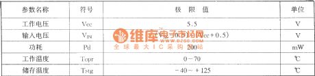
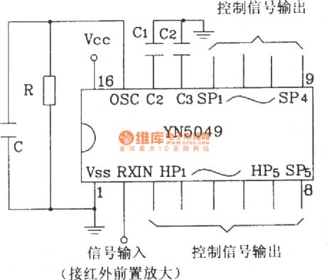
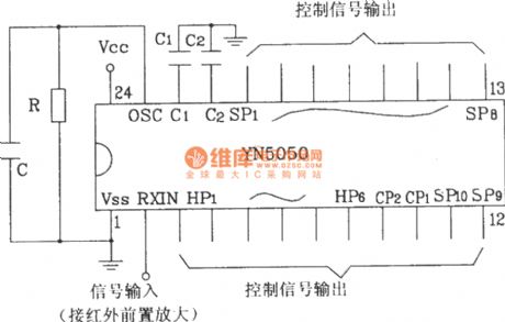
YN5049/5050 Infrared remote control receiver typical application circuit diagram
Published:2011/4/22 2:53:00 Author:Rebekka | Keyword: Infrared remote control, receiver typical application
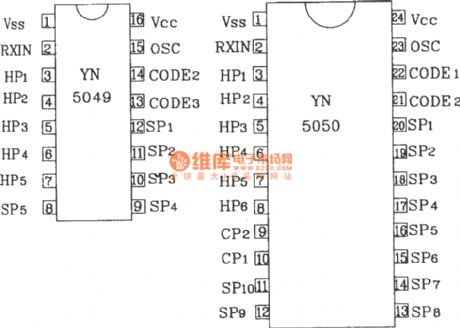
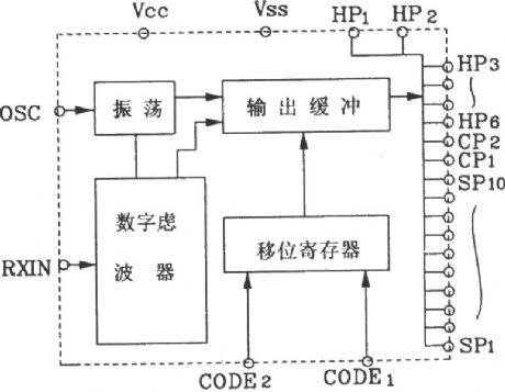
YN5049/5050 multiple infrared remote receiver is a dedicated remote control receiver IC that uses with YN5048 multiple infrared remote control transmitter fetters. They are mainly used in TV, stereo, VCR and other home appliances remote areas. There are similar models BL9150, TC9150.
YN5049/5050 shape pin map.
YN5050 internal block diagram.
YN5049/5050 infrared remote control receiver limit operating parameters.
(1)
(2)
(1), (2) are infrared remote control receiver YN5049/5050 typical application circuit
(View)
View full Circuit Diagram | Comments | Reading(1703)
Ratio motor wireless remote control circuit diagram
Published:2011/4/20 4:19:00 Author:Rebekka | Keyword: Ratio motor wireless , remote control
Ratio motor wireless remote control transmitter circuit.
Ratio motor wireless remote control receiver circuit.
IC2 is the LM386. It is a good performance low-power audio amplifier integrated circuits. It is widely used.
(View)
View full Circuit Diagram | Comments | Reading(3044)
Monitor and TV high-voltage (KV level) protection circuit diagram
Published:2011/4/26 2:13:00 Author:Rebekka | Keyword: Monitor, TV , high-voltage protection
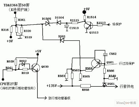
Monitor and TV high-voltage (KV level) protection circuit diagram is shown as above. (View)
View full Circuit Diagram | Comments | Reading(2001)
100 in 1 Multi-function VCD remote control circuit(compatible with co-RM-220 and NT66P13)
Published:2011/4/20 5:03:00 Author:Rebekka | Keyword: VCD remote control
View full Circuit Diagram | Comments | Reading(783)
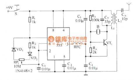
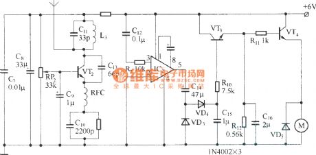
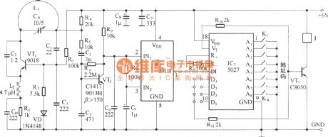
Ultra-small 400 meters wireless remote control circuit diagram
Published:2011/4/24 10:03:00 Author:Rebekka | Keyword: wireless remote control
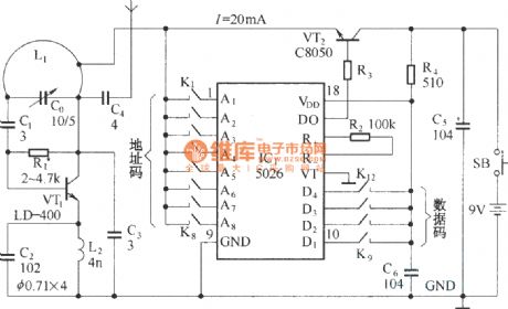
Transmitter circuit:
Receiver circuit:
Ultra-small wireless remote control use 400-meter digital encoder / decoder VD5026/VD5027 as the core and use emission-specific transistor LD-400, the remote distance is far, its operation stable and reliable. (View)
View full Circuit Diagram | Comments | Reading(2703)
Electric single-girder crane remote control circuit diagram
Published:2011/4/24 11:42:00 Author:Rebekka | Keyword: Electric single-girder, crane remote control
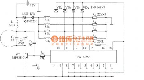
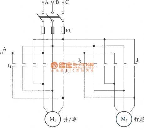

Electric single-girder cranes is also known as electric hoist. It is commonly used in small factories lifting handling equipment. Usually it is always used with drag line switching noytoperation, which is not very convenient. The circuit is composed of radio remote control radio remote control component TWH9236/38 circuit. It is shown as above. Remote control transmitter is the finished piece, that TWH9236, the internal schematic is shown as above.
Remote control receiver control circuit is shown as below.
(View)
View full Circuit Diagram | Comments | Reading(5299)
| Pages:28/34 At 202122232425262728293031323334 |
Circuit Categories
power supply circuit
Amplifier Circuit
Basic Circuit
LED and Light Circuit
Sensor Circuit
Signal Processing
Electrical Equipment Circuit
Control Circuit
Remote Control Circuit
A/D-D/A Converter Circuit
Audio Circuit
Measuring and Test Circuit
Communication Circuit
Computer-Related Circuit
555 Circuit
Automotive Circuit
Repairing Circuit