
Remote Control Circuit
Index 24
TV remote controller 15
Published:2011/5/19 8:08:00 Author:TaoXi | Keyword: TV, remote controller
TV remote controller 15 (View)
View full Circuit Diagram | Comments | Reading(637)
TV remote controller 12
Published:2011/5/19 8:10:00 Author:TaoXi | Keyword: TV, remote controller
TV remote controller 13 (View)
View full Circuit Diagram | Comments | Reading(627)
TV remote controller 13
Published:2011/5/19 8:10:00 Author:TaoXi | Keyword: TV, remote controller
TV remote controller 13 (View)
View full Circuit Diagram | Comments | Reading(704)
TV remote controller 14
Published:2011/5/19 8:09:00 Author:TaoXi | Keyword: TV, remote controller
TV remote controller 14 (View)
View full Circuit Diagram | Comments | Reading(692)
wide range timing switch circuit
Published:2011/5/19 1:20:00 Author:TaoXi | Keyword: wide range, timing switch
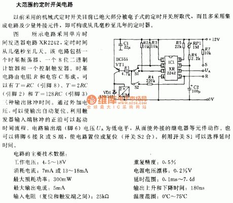
The wide range timing switch circuit
This circuit uses the monolithic time transmitter circuit XR2242, the timing range is from few milliseconds to few days. This circuit is composed of a time-based oscillator, a 8-bit binary counter and a control trigger. The time-base circuit is composed of the resistor R and capacitor C, there are three kinds of output pulse time: T=RC (pin 8), T=2RC (pins 2) and T=128RC (pin 3). Through the additional voltage, we can make the output automatic reset. By using the positive edge of the trigger input port pulse, we can start the time process.
(View)
View full Circuit Diagram | Comments | Reading(836)
Twelve-channel wireless remote control circuit TH9738
Published:2011/5/11 19:54:00 Author:TaoXi | Keyword: Twelve-channel, wireless remote control
The key components datathat will be used in this artical:
TH9738 CD4514 78L05 9014 (View)
View full Circuit Diagram | Comments | Reading(739)
General timing controller circuit
Published:2011/5/18 3:56:00 Author:TaoXi | Keyword: General, timing, controller
General timing controller circuit (View)
View full Circuit Diagram | Comments | Reading(684)
Time adjustable timer circuit
Published:2011/5/17 21:49:00 Author:TaoXi | Keyword: Time, adjustable, timer
Time adjustable timer circuit (View)
View full Circuit Diagram | Comments | Reading(725)
Double-watch timer circuit (2)
Published:2011/5/17 20:35:00 Author:TaoXi | Keyword: Double-watch, timer circuit
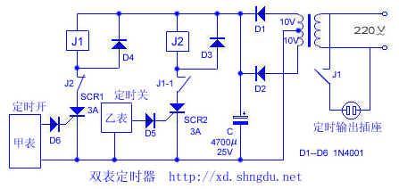
AC220V is reduced by the transformer B and is full-wave rectified by the diode D1 and D2, then is filtered by the capacitance C, so we get the 14V DC voltage, this voltage can be added to the both ends of the SCR1, when the watch A outputs a timing alarm clock pulse (open), SCR1 is conducted, relay J1 gets the electricity and it's contact-point J1 closes, timing socket has the electricity to output, meanwhile J1-1's contact-point closes to make the preparation for SCR2 conduction, when the time is up,watch B outputs a timing alarm clock pulse (close), SCR2 is conducted, it's contact-point J2 cuts off, SCR1 cuts off too, also it's contact-points J1 and J1-1. Timing socket has no electricity to output. J2 recovers the closing state.
(View)
View full Circuit Diagram | Comments | Reading(945)
Simple and practical constant temperature controller circuit
Published:2011/5/18 18:55:00 Author:TaoXi | Keyword: Simple, practical, constant temperature controller
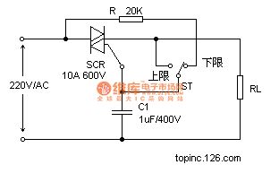
The working principle is: ST is the WTQ-288 type electrical contact point pressure type thermometer, when the temperature of incubator reduces to the lower limit, ST's pointer contacts with the lower limit contact point, the bidirectional thyristor is forced to trigger conduction, and you connect heater RL's power supply, so the temperature of incubator rises. ST's pointer turns and separates from the lower limit contact point. Although the trigger circuit is disconnected, but for the capacitance C's phase shifting effect, when the supply voltage crosses zero, the capacitive current is not zero, so when the power is inverted, it still provides the trigger current for the triac to keep the conduction. (View)
View full Circuit Diagram | Comments | Reading(1206)
Simple delay timing circuit
Published:2011/5/18 10:42:00 Author:TaoXi | Keyword: Simple, delay timing
Simple delay timing circuit (View)
View full Circuit Diagram | Comments | Reading(742)
The remote controlled door lock circuit of Buick-Century
Published:2011/5/17 21:47:00 Author:Borg | Keyword: door lock, Buick-Century
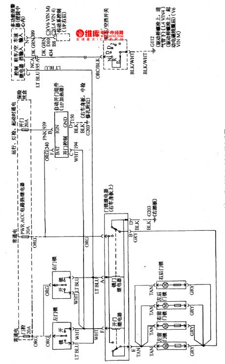
The left-front lock switch is in parallel with right-front door lock, when the lock switch is at lock position, the lock relay will drive the 4 lock motors to lock all the doors; when the switch is in unlock state, the relay will make right-front, right-rear and left-rear door open, and the left-front door is opened by the driver.If there were no remote modules, such as in Figure 2,actions likeopening the door or locking the door would be done by keys or door lock switches.
(View)
View full Circuit Diagram | Comments | Reading(1487)
Three-phase four-wire phase lack protection circuit
Published:2011/5/17 20:58:00 Author:TaoXi | Keyword: Three-phase, four-wire, phase lack, protection circuit
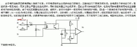
Because the current transformer's testing cost is too high, and the volume is big, so the switching power supplies always use the electronic phase lack protection circuit. Figure 5 is a simple electronic phase lack protection circuit. When the three-phase is balance, R1~R3's node H has the low level voltage, the optical coupling output is nearly the zero level. When the phase is lack, H's electric potential increases, the optical coupling output is high level, and it is compared by the comparator, then it outputs the low level voltage to blockade the driving signal. The standard of the comparator is adjustable, so you can adjust the phase lack action value. This phase lack protection circuit can be used in the standard of three-phase four-wire but not the three-phase four-wire.
(View)
View full Circuit Diagram | Comments | Reading(999)
Hotbox Overheating Protection Schematic Circuit
Published:2011/5/17 4:05:00 Author:Sharon | Keyword: Hotbox, Overheating Protection
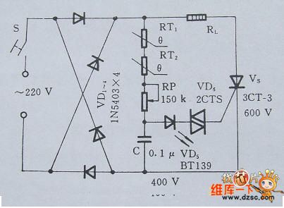
Figure 1 is a schematic circuit of hotbox overheating protection circuit. Under normal circumstances, adjust RP1 so that Ui ≥ 2Uc / 3, and position 7's output is adjusted from high potential to low potential. K then opens its normally closed contacts and cut off power for equipment running to protect the bearing or bearings. (View)
View full Circuit Diagram | Comments | Reading(1284)
Hotbox Overheating Components Circuit
Published:2011/5/17 3:54:00 Author:Sharon | Keyword: Hotbox, overheating components
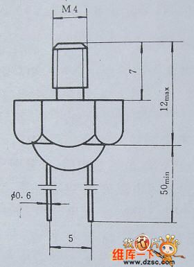
Figure 1 Typical dimensions of temperature probe
PTC thermistor RT is a key component in hotbox overheating protection circuit, and its room temperature resistance is ≤ 500Ω.Its typical dimension is shown in Figure 2.10.2. The shell is made from brass screws with PTC thermistor sealed inside, and it's ensured a good heat conduction and electrical insulation with the shell.
(View)
View full Circuit Diagram | Comments | Reading(867)
silk screen exposure timer circuit
Published:2011/5/17 19:15:00 Author:TaoXi | Keyword: silk screen, exposure, timer circuit
silk screen exposure timer circuit is as shown: (View)
View full Circuit Diagram | Comments | Reading(672)
Gateball competition timer circuit
Published:2011/5/17 19:14:00 Author:TaoXi | Keyword: Gateball competition, timer circuit
Gateball competition timer circuit is as shown: (View)
View full Circuit Diagram | Comments | Reading(735)
Wireless remote control switch circuit 7
Published:2011/5/9 0:54:00 Author:Rebekka | Keyword: Wireless remote control switch
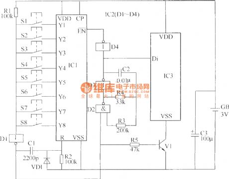
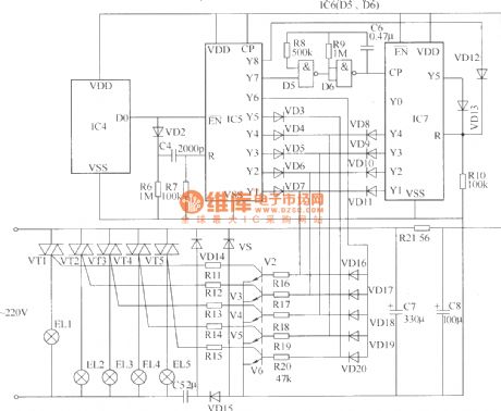
The wireless remote control switch circuit is composed of the wireless remote control transmitter and receiver wireless remote control circuit. The radio remote control transmitter circuit is composed of the pulse encoder circuit and radio transmitter circuit. It is shown as above.
Components selectionR1 ~ R20 uses 1/4W carbon film resistors or metal film resistors; R21 chooses 1/2W metal film resistors. C1 and C4 use high-frequency ceramic capacitors; C2 and C6 use monolithic capacitors; C3 and C7, C8 use electrolytic capacitors voltage 16V; C5 uses voltage 400V CBB capacitors. VD1 ~ VD13 and VD16 ~ VD20 use 1N4148 silicon switch diode; VD14 and VD15 use 1N4007 type silicon rectifier diodes.VS uses 1W, 6.2V silicon voltage regulator diodes. V1 ~ V6 use S9013 or C8050, S8050, 3DG9013, 3DG8050 silicon NPN transistor. VT1 ~ VT5 use TLC336A (3A, 600V) type bidirectional thyristor. IC1, IC5 and IC7 use CC4017 or CD4017 type decimal counting / pulse divider circuits; IC2 and IC6 use CC4011 or CD4011 type four NAND gate integrated circuit ; IC3 uses T630 type radio transmitter IC; IC4 uses T631 type radio receiver integrated circuit.S1 ~ S8 use tiny moving together (normally open) button. GB uses two 5 batteries. (View)
View full Circuit Diagram | Comments | Reading(1881)
The circuit diagram of highly accurate current output integrated temperature sensor AD592 matching A/D converter
Published:2011/5/16 20:49:00 Author:Nicole | Keyword: current output, integrated temperature sensor, A/D converter
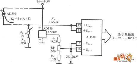
In microcontroller temperature measuring system, firstly, AD592 outputed analog is changed into digital by A/D converter, then it is sent to single chip and data processed. The AD592 matching A/D converter circuit is shown in the figure. It adopts a AD670 to transfer 8-bit A/D. AD670 is 4 terminal differential input, it contains input attenuator, instrumentation amplifier and 8-bit A/D converter of reference voltage source. The current signal exported by AD592 is transformed into voltage signal by R1 and R2, the voltage temperature coefficient is 1mV/℃.
(View)
View full Circuit Diagram | Comments | Reading(2295)
Remote controller part circuit
Published:2011/5/17 1:35:00 Author:Christina | Keyword: Remote controller
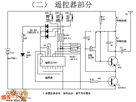
Figure: Remote controller part circuit (View)
View full Circuit Diagram | Comments | Reading(946)
| Pages:24/34 At 202122232425262728293031323334 |
Circuit Categories
power supply circuit
Amplifier Circuit
Basic Circuit
LED and Light Circuit
Sensor Circuit
Signal Processing
Electrical Equipment Circuit
Control Circuit
Remote Control Circuit
A/D-D/A Converter Circuit
Audio Circuit
Measuring and Test Circuit
Communication Circuit
Computer-Related Circuit
555 Circuit
Automotive Circuit
Repairing Circuit