
Remote Control Circuit
Index 27
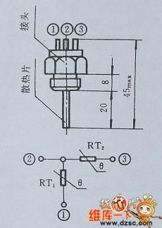
Temperature control circuit of the fan
Published:2011/5/9 18:44:00 Author:TaoXi | Keyword: Temperature control, fan
The Temperature control circuit of the fan: (View)
View full Circuit Diagram | Comments | Reading(757)
M58480P-remote control emission integrated circuit diagram
Published:2011/5/6 22:44:00 Author:Nicole | Keyword: remote control, emission
M58480P is a remote control emission integrated circuit which is produced by Mitsubishi Corp, it is used as infrared singal process in the system.
1. internal circuit block diagram and pin function
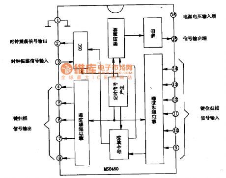
M58480P integrated circuit contains key instruction singal compiling, decoding circuit, path instruction decode circuit, the internal circuit block diagram and pin function of this integrated block is shown in the figure1.
2. practical data
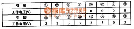
M58480P's all kinds of pin working voltage which is used in remote control transmitter is shown in the table1.
The figure1 is the internal circuit block diagram and pin function of M58480P integrated block
The table1 is the M58480P's all kinds of pin working voltage which is used in remote control transmitter
(View)
View full Circuit Diagram | Comments | Reading(970)
Multi-function remote control circuit (555、LM909)
Published:2011/5/8 9:10:00 Author:TaoXi | Keyword: Multi-function, remote control circuit
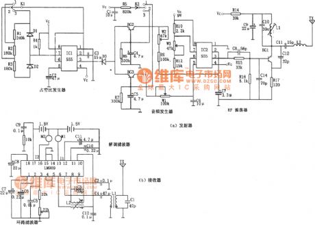
The Multi-function remote control circuit (555、LM909) is as shown:
(View)
View full Circuit Diagram | Comments | Reading(1038)
BX1323 remote control signal receiving integrated circuit diagram
Published:2011/5/8 4:57:00 Author: | Keyword: BX1323, remote control signal receiving
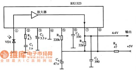
BX1323 is a remote control signal receiving integrated circuit.It's widely used as a remote control signal receiving circuit. in air conditioning, color TV sets, audio equipment, DVD players and other remote control system.
1.Features
BX1323 integrated circuit includes remote control signal preamplifier circuit, band-pass filter circuit, detector, buffer circuit.
2.pin functions and data
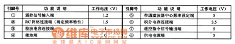
BX1323 integrated circuit uses 8-pin single in-line package.The pin functions and data are shown in Table 1.
Table 1 BX1323 integrated circuit's pin functions and data
3.Typical application circuit
Theremote control signal receiving typical application circuit which is posed by the BX1323 integrated circuit is shown in Figure 1.
Figure 1 The typical application circuit of the BX1323 integrated circuit
(View)
View full Circuit Diagram | Comments | Reading(843)
A Protection Circuit of Default Phases of Three-Phase Three-Wire Power Sources
Published:2011/5/7 19:48:00 Author:Borg | Keyword: Default Phases, Three-Phase, Three-Wire, Power Sources

The following is a circuit used toprotect the defult-phases of three-phase three-wire power sources. Without anyone of A,B or C, the electrical level (LEV) that the optical coupler output will be lower than the reference voltage that the inverting input node of the comparator holds, and the latter will low LEV to block the PWN driving signals, finally, the supply power will be shut down. Besides, if the input polar of the comparator changes, the PWM signals can also be blocked by high LEV. This circuit separates heavy currents by optocouplers, which is safe to use, while RP1 and RP2 are used to adjust the threshold values of the protecting behaviors. (View)
View full Circuit Diagram | Comments | Reading(971)
The Control Circuit of Timing in Turn
Published:2011/5/7 20:13:00 Author:Borg | Keyword: Control Circuit, Timing, in Turn
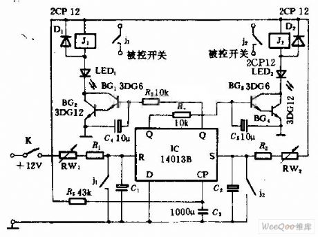
This circuit can periodically control two switches in turn, the control time ranges from several seconds to dozens of seconds freely;when it is used a forward and reversely moving machine control, it can make the motor periodically move back and forward accordingly.
(View)
View full Circuit Diagram | Comments | Reading(775)
Air-conditioning control panel circuit including an main control board and remote control PIC16C54
Published:2011/4/8 3:01:00 Author:Rebekka | Keyword: Air-conditioning control panel, control board , remote control
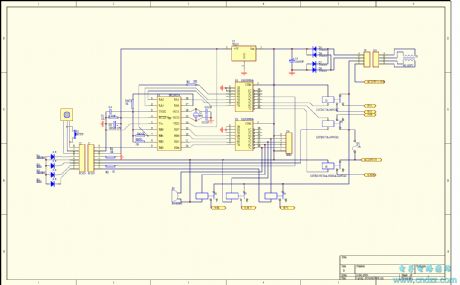
View full Circuit Diagram | Comments | Reading(4433)
Digital long delay circuit
Published:2011/4/20 9:10:00 Author:Nicole | Keyword: digital, long delay


Ordinary long time delay circuit is usually with the help of electrolytic capacitor or high impedance circuit. This circuit has poor stability, and the accuracy of delay also is not high.
Here is a digital long delay circuit, it casts behind the electrolytic capacitor and high impedance circuit absolutely, the accuracy of delay is high.
The core of this circuit is the integrated block MC14521B, it is a 24 class clock division circuit, it contains inverters which composed of oscillation circuit. If the trigger input terminal is grounding or without signal, then the circuit is into delay state, the delay time is adjusted by the range switch X and 100KΩ potentiometer.
If X is connected to point A, the delay time is from 1 minute 40 seconds to 18 minutes 30 seconds, if X is connected to point B, the delay time is from 13 minutes 20 seconds to 2 hours 28 minutes. If X is connected to point C, the delay time is from a hour 47 minutes to 20 hours. The specific delay time is set by 100KΩ potentiometer. If it needs longer delay, you can use bulky capacitor insteads of 39nF capacitor. Then the delay time will reach more than one week. Added a positive signal on the trigger input terminal, the divider in 4521B can be reset.
The delay is reliable and steady, it can use 6~15V regulated power supply. The prototype adopts 12V power supply.
(View)
View full Circuit Diagram | Comments | Reading(937)
SCR (two-way) Speed Test Circuit
Published:2011/5/5 9:56:00 Author:Felicity | Keyword: SCR (two-way), Speed Test Circuit,
The picture above shows the SCR (two-way) Speed Test Circuit. (View)
View full Circuit Diagram | Comments | Reading(1064)
Battery Determined Thyristor Circuit
Published:2011/5/5 9:55:00 Author:Felicity | Keyword: Battery Determined, Thyristor Circuit,
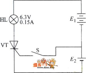
The picture above shows the Battery Determined Thyristor Circuit. (View)
View full Circuit Diagram | Comments | Reading(723)
Circuit of SCR Measured by Multimeter
Published:2011/5/5 9:55:00 Author:Felicity | Keyword: SCR, Measured by Multimeter,
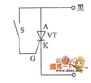
The picture above shows the circuit of SCR measured by multimeter. (View)
View full Circuit Diagram | Comments | Reading(709)
Five functions ultrared remote control receiving circuit diagram
Published:2011/5/5 21:26:00 Author:Nicole | Keyword: function, ultrared remote control, receiving
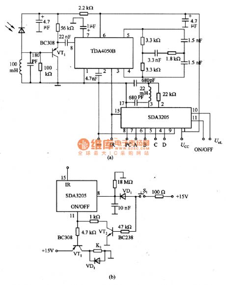
The figure1 is a five functions ultrared remote control receiving circuit. In the figure 1(a), SDA205 is ultrared remote control receiving decoding integrated circuit, after it receives a series of instructions which is sent by transmitting circuit, it will start to work. If the instructions are program advances P+ and program advances P- , then the ring counter has 16 channels selection, it outputs A, B, C, D. If the instruction is simulation+ and simulation - it can be used for voice controlling(output UOL). The fifth function is ON/OFF , when it is off, the device is in standby state, PC terminal outputs high level, TV's channel transformation is no effect. If it is changed into the circuit as shown in the figure1(b), it still can be remote controlled, swtich S1 is pressed, then VT2 turns on, standby output terminal ON/OFF is enforced into low level. When input PC is high level, for the ring counter, it is program advances P+ . In standby action, PC output is high level, because it is connected to diode VD1, VT2 turns off, so it is no influence on circuit. K1 is standby relay.
(View)
View full Circuit Diagram | Comments | Reading(938)
Automatic water supply circuit
Published:2011/5/4 18:53:00 Author:Christina | Keyword: Automatic, water supply
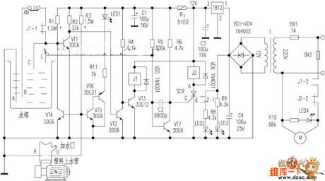
The water tower automatic protection circuit is as shown: household low-power water pumps has no protection measures, so it is easy to leak, and the electric motor is damaged because there is water, or the automatic control circuit is not work to cause the water overflow. The author adds the automatic protection circuit to this circuit, and realizes the water tower unmanned management, this circuit is simple and safe:
Figure Automatic water supply circuit (View)
View full Circuit Diagram | Comments | Reading(1588)
Digital displaying remote control electric fan circuit diagram
Published:2011/5/4 3:55:00 Author:Ecco | Keyword: Digital , displaying, remote control, electric fan
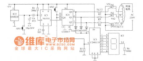
Remote control fan circuit is shown as the chart, the remote distance is about 8m, and it does not need dedicated remote control. With an infrared remote control at any infrared receiver by pressing a key, IC2 will receive the infrared pulse signal, and make filter, detect, amplifier and other processing, the signal is coupled to IC3 by C6, Schmid special trigger composed of IC3 and will make shape on pulse signal to obtain the ideal square wave. R1 is pull-up resistor, the appropriate resistance can greatly improve the circuit's noise immunity. The resistance of R1 is in the range of 200kΩ ~ 470kΩ, R1 is too small to reduce the circuit sensitivity; too high to reduce the general assembly performance. After shaping the pulse signal, it is output from 3 feet, and then carried into the CD4017 decade counter to make pulse count. The output end Q0 of CD4017 outputs high level, others outputs low level. The output high level is sent to be decoded by diodes, the driver CD40110 makes the digital display 1.
(View)
View full Circuit Diagram | Comments | Reading(1704)
Tape recorder remote control display circuit
Published:2011/4/29 4:52:00 Author:Nicole | Keyword: tape recorder, remote control
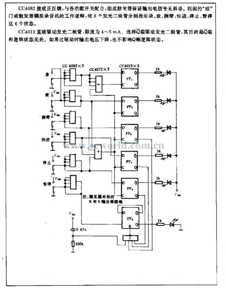
CC4082 is connected into positive feedback, it is coordinated with all kinds function switches, they form a trigger to ensure the output electrical signal against chattering. The later or gate or trigger simulates the work logic of tape recorder, the six LEDs indicate the six states of recording, putting, rewinding, fast marching, stopping, time-out.
CC4013 drives LED directly, the limited current is 4~5mA. To choose Q terminal to drive LED, because the Q terminal is unrelated to logic state. If the output voltage drops, it has no influence on Q terminal logic state. (View)
View full Circuit Diagram | Comments | Reading(735)
SC612 infrared ray remote control emission circuit
Published:2011/5/3 2:36:00 Author:May | Keyword: infrared ray, remote control emission
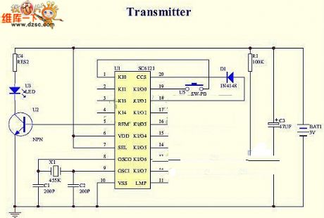
SC612 infrared ray remote control emission circuit is shown in the following picture:
(View)
View full Circuit Diagram | Comments | Reading(960)
The Constant Temperature Attemperation Circuit of Film Flushing Liquor
Published:2011/5/3 6:23:00 Author:Christina | Keyword: Constant Temperature, Attemperation, Film Flushing Liquor
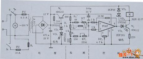
TheThe Constant Temperature Attemperation Circuit of Film Flushing Liquor is as shown in figure 1, this circuit contains three parts: detecting, controlling, and the power supply.
Figure 1. The Constant Temperature Attemperation Circuit of Film Flushing Liquor
Selection of the main components
To ensure the temperature adjustment accuracy, resistors R1 and R2 need to use the manganese bronze precision wirewound resistor with 0.05% accuracy; in addition, to ensure the uniformity of lotion's temperature, you need to install the promise speed mixer. The RL heating power is less than 2KW. (View)
View full Circuit Diagram | Comments | Reading(744)
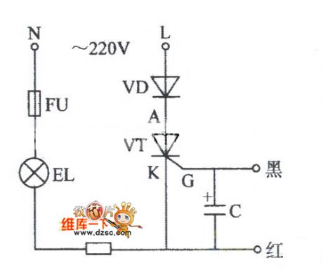
Beside-heating PTC water-cutoff component selection circuit
Published:2011/5/3 7:19:00 Author:Christina | Keyword: Beside-heating, PTC, water-cutoff, component selection
The relay's selection depends on the load power of the controlled equipment, this JQX-15F-B-type normally close contact-point relay is suitable for the mechanical & electrical equipments with the current lower than 12A. (View)
View full Circuit Diagram | Comments | Reading(896)
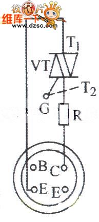
Thyristor Circuit Judged by Electricity
Published:2011/5/3 7:55:00 Author:Felicity | Keyword: Thyristor Circuit Judged by Electricity,
The picture above shows the thyristor circuit judged by electricity. (View)
View full Circuit Diagram | Comments | Reading(825)
Triac Tested by Digital Multimeter Circuit
Published:2011/5/3 7:49:00 Author:Felicity | Keyword: Triac Tested by Digital Multimeter Circuit,
The picture above shows the Triac Tested by Digital Multimeter Circuit. (View)
View full Circuit Diagram | Comments | Reading(826)
| Pages:27/34 At 202122232425262728293031323334 |
Circuit Categories
power supply circuit
Amplifier Circuit
Basic Circuit
LED and Light Circuit
Sensor Circuit
Signal Processing
Electrical Equipment Circuit
Control Circuit
Remote Control Circuit
A/D-D/A Converter Circuit
Audio Circuit
Measuring and Test Circuit
Communication Circuit
Computer-Related Circuit
555 Circuit
Automotive Circuit
Repairing Circuit