
Remote Control Circuit
Index 33
Sequential timer circuit
Published:2011/4/1 1:48:00 Author:Nicole | Keyword: sequential timer


The 556 double timer transports the first half to the latter half by 0.001μF coupling capacitance, giving a total delay which is equal to the sum of single delay. The moment of 6-pin grounding can start the first half of timer. After determining the time interval by 1.1R1C1, the second timer starts delaying, the value is decided by 1.1R2C2.
(View)
View full Circuit Diagram | Comments | Reading(1919)
Electronic clock improvement circuit diagram
Published:2011/4/2 2:16:00 Author:Nicole | Keyword: Electronic clock
View full Circuit Diagram | Comments | Reading(706)
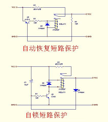
Short-circuit protector with relay
Published:2011/4/2 2:19:00 Author:Nicole | Keyword: short-circuit protector, relay
View full Circuit Diagram | Comments | Reading(981)
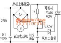
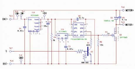
High power DC motor speed control circuit
Published:2011/4/2 2:22:00 Author:Nicole | Keyword: motor speed control
View full Circuit Diagram | Comments | Reading(1600)
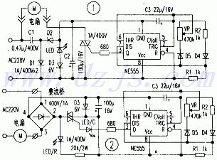
Electric fan stepless speed regulation circuit
Published:2011/4/2 2:29:00 Author:Nicole | Keyword: electric fan, stepless speed regulation
View full Circuit Diagram | Comments | Reading(940)
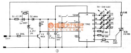
Y982 electric heater temperature control circuit
Published:2011/4/2 2:34:00 Author:Nicole | Keyword: electric heater, temperature control

View full Circuit Diagram | Comments | Reading(1425)
Typical application circuit of ZN1034E long delay control integrated circuit
Published:2011/4/2 2:51:00 Author:Nicole | Keyword: control integrated circuit
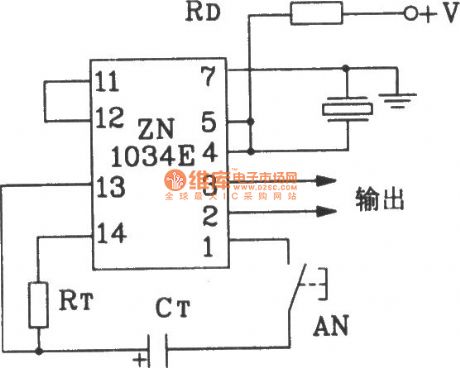
The RT in figure can be chosen between 5kΩ~5MΩ. Considering operate easily and linearity, it is better to choose 250kΩ~1MΩ. The preferred value of CT is over 0.01pF, and the minimum value should not lower than 3 900pF according to the manufacturer's recommendations.
(View)
View full Circuit Diagram | Comments | Reading(1677)
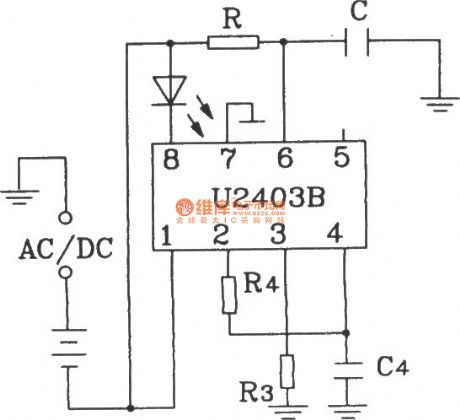
Typical application circuit of U2403B constant source charging timer
Published:2011/4/2 2:55:00 Author:Nicole | Keyword: constant source, charging timer
View full Circuit Diagram | Comments | Reading(820)
Long pulse timer circuit
Published:2011/4/2 3:17:00 Author:Nicole | Keyword: timer
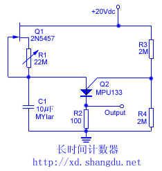
This timer circuit can provide 20min counting time delay. It is a normal decline oscillator with FET current source. Resistance R1 provides reverse migration to the door of JFET transform into power supply. It colses JFET and delays the charging time of C1. C1 is a low drain capacitance similar to polyester resin.
(View)
View full Circuit Diagram | Comments | Reading(1162)
MA21 miniature electronic governor circuit
Published:2011/4/2 3:42:00 Author:Nicole | Keyword: electronic governor
View full Circuit Diagram | Comments | Reading(1906)
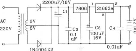
Typical application circuit of S1633A Ni-Cd battery charge control integrated circuit
Published:2011/4/2 3:45:00 Author:Nicole | Keyword: Ni-Cd battery, charge control, integrated circuit
View full Circuit Diagram | Comments | Reading(766)
Typical application circuit of RS6445C long-time timing integrated circuit
Published:2011/4/2 3:53:00 Author:Nicole | Keyword: long-time timing, integrated circuit

The timing time in figure is decided by timing R.C components R, C and 4, 5 pins preset level B, A. The value of timing time T=2/3•1024•N•R•C is determined by A, B, in theory.
(View)
View full Circuit Diagram | Comments | Reading(863)
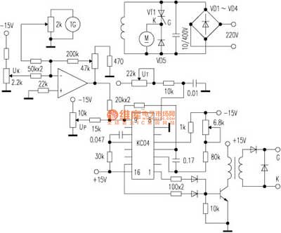
Speed regulation circuit with integrated trigger KC04
Published:2011/4/2 3:56:00 Author:Nicole | Keyword: speed regulation, integrated trigger
View full Circuit Diagram | Comments | Reading(785)
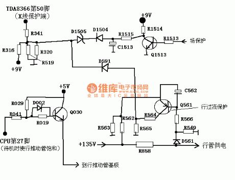
Kind of KV protection circuit
Published:2011/4/2 3:57:00 Author:Nicole | Keyword: KV protection
View full Circuit Diagram | Comments | Reading(677)
Single on-off timing control application circuit composed of MC14541 special timing integrated circuit
Published:2011/4/2 4:10:00 Author:Nicole | Keyword: on-off timing, special timing, integrated circuit
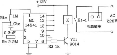
MC14541 is a programmable timing special IC. The timing time of this circuit is 3 hours, you can through selecting RTc、CTc、Rs to choose the time of required control power on-off.
(View)
View full Circuit Diagram | Comments | Reading(7733)
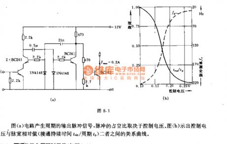
Pulse width regulator circuit
Published:2011/3/22 22:43:00 Author:Jessie | Keyword: pulse, width regulator
View full Circuit Diagram | Comments | Reading(675)
Adjustable relay delay switch circuit
Published:2011/3/22 22:44:00 Author:Jessie | Keyword: relay, delay, switch
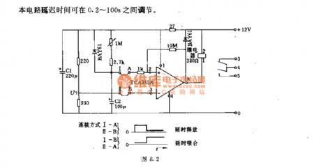
Technical characteristicsWorking voltage: 10~16 VSwitch power: ~ 2kVARepeat preparation time: < 250ms
(View)
View full Circuit Diagram | Comments | Reading(1253)
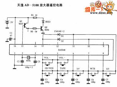
Tianyi AD-5100 amplifier remote control circuit
Published:2011/3/21 0:57:00 Author:may | Keyword: Tianyi, amplifier remote control
View full Circuit Diagram | Comments | Reading(904)
μPC1373H application circuit
Published:2011/3/28 22:02:00 Author:may
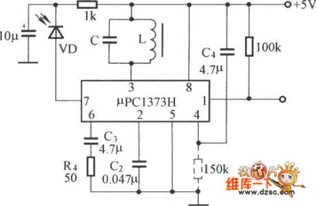
μPC1373H application circuit is shown in the diagram:
(View)
View full Circuit Diagram | Comments | Reading(892)
Fan speed control circuit with remote control
Published:2011/3/21 1:38:00 Author:Allen | Keyword: Fan speed control, remote control

View full Circuit Diagram | Comments | Reading(1871)
| Pages:33/34 At 202122232425262728293031323334 |
Circuit Categories
power supply circuit
Amplifier Circuit
Basic Circuit
LED and Light Circuit
Sensor Circuit
Signal Processing
Electrical Equipment Circuit
Control Circuit
Remote Control Circuit
A/D-D/A Converter Circuit
Audio Circuit
Measuring and Test Circuit
Communication Circuit
Computer-Related Circuit
555 Circuit
Automotive Circuit
Repairing Circuit