
Signal Processing
Index 3
2.34kHz sine wave oscillator circuit diagram
Published:2014/4/29 20:56:00 Author:lynne | Keyword: 2.34kHz sine wave oscillator circuit diagram, LM3900
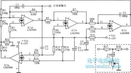
2.34kHz sine wave oscillator circuit diagram as shown:
(View)
View full Circuit Diagram | Comments | Reading(1573)
1-50kHz sine wave oscillator circuit diagram
Published:2014/4/29 20:55:00 Author:lynne | Keyword: 1-50kHz sine wave oscillator circuit diagram, 2N2160
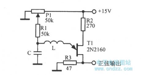
1-50kHz sine wave oscillator circuit diagram as shown:
(View)
View full Circuit Diagram | Comments | Reading(2126)
"NAND" gate TTL crystal oscillator
Published:2014/4/29 20:53:00 Author:lynne | Keyword: "NAND" gate TTL crystal oscillator, 7400
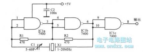
NAND gate TTL crystal oscillator as shown:
(View)
View full Circuit Diagram | Comments | Reading(2886)
Multi-frequency signal generator circuit diagram
Published:2014/4/28 21:00:00 Author:lynne | Keyword: Multi-frequency signal generator circuit diagram, 2N3019, 374C14N
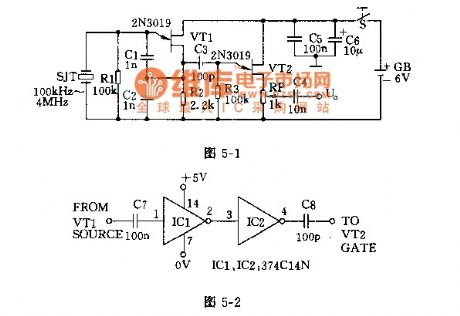
Multi-frequency signal generator circuit diagram shown as follow:
(View)
View full Circuit Diagram | Comments | Reading(1719)
Square wave, sine wave generator circuit diagram
Published:2014/4/28 21:15:00 Author:lynne | Keyword: Square wave, sine wave generator circuit diagram

Square wave, sine wave generator circuit diagram as shown:
(View)
View full Circuit Diagram | Comments | Reading(2325)
450/800 hz signal generator circuit diagram
Published:2014/4/28 21:17:00 Author:lynne | Keyword: 450/800 hz signal generator circuit diagram, 3DG12B
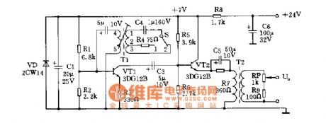
450/800 hz signal generator circuit diagram shown as follow:
(View)
View full Circuit Diagram | Comments | Reading(1434)
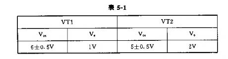
50 ~ 1000 KHZ transistor oscillator
Published:2014/4/28 21:20:00 Author:lynne | Keyword: 50 ~ 1000 KHZ transistor oscillator
50 ~ 1000 KHZ transistor oscillator shown as follow:
(View)
View full Circuit Diagram | Comments | Reading(2648)
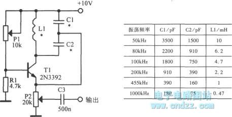
10 MHZ variable frequency oscillator
Published:2014/4/28 21:21:00 Author:lynne | Keyword: 10 MHZ variable frequency oscillator, MPF102
10 MHZ variable frequency oscillator as shown:
(View)
View full Circuit Diagram | Comments | Reading(1960)
MD-898K metal detector schematic circuit diagram
Published:2014/4/21 19:55:00 Author:lynne | Keyword: MD-898K metal detector schematic circuit diagram, MD-898K
MD-898K metal detector schematic circuit diagram shown as follow:
(View)
View full Circuit Diagram | Comments | Reading(2969)
Signal repeater circuit schematic
Published:2014/4/16 20:40:00 Author:lynne | Keyword: Signal repeater circuit schematic, RC4558
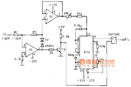
Illustrates the use of two operational amplifiers constituting the signal and a frequency-voltage converter A1.A2 transfer circuit 4153, the input signal UF amplitude varies between -10 ~-10V, the output signal UA, issued by the exclusive or gate. A1.A2 op amp can be used RC4558 or other models can be used 2N222 transistor VT1 or similar model, resistor R1 (10Ω) accuracy class shall be of ± 0.1%. As shown in Figure transponder signal circuit schematics:
(View)
View full Circuit Diagram | Comments | Reading(1886)
Oscillator infrared transmitter circuit diagram
Published:2014/4/14 22:03:00 Author:lynne | Keyword: Oscillator infrared transmitter circuit diagram
Oscillator infrared transmitter circuit diagram shown as follow:
(View)
View full Circuit Diagram | Comments | Reading(1371)
Oscillator (ceramic) infrared emission circuit principle diagram
Published:2014/4/7 21:35:00 Author:lynne | Keyword: Oscillator (ceramic) infrared emission circuit principle diagram
Oscillator (ceramic) infrared emission circuit principle diagram shown as following:
(View)
View full Circuit Diagram | Comments | Reading(1328)
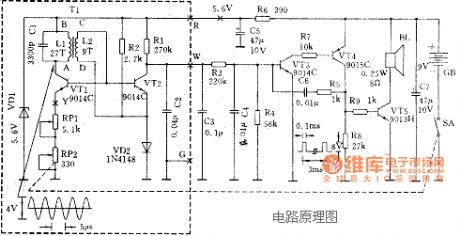
High loudness alert tone generator circuit diagram
Published:2014/1/24 20:10:00 Author:lynne | Keyword: High loudness alert tone generator circuit diagram, 1N4001, TWH8778
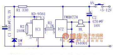
The warning tone generator circuit is simple, stable and reliable performance, working voltage 6V-12V, suitable for the siren in the car, motorcycle use. The circuit mainly by the sound IC KD ~ 9561 TWH8778 and switch integrated circuit composed of work by KD-9561 audio output warning signal after TWH8778 high current switching IC processing amplified loud speaker to promote sound the alarm. Components Selection: IC with KD-9561 sound IC, KD-9562 can also use sound IC, the wiring required to make sound an alarm tone alarm signal. IC2 use TWH8778 switching circuit, when the supply voltage is 12V, the speaker BL should choose 8Ω, 3W speakers or a dedicated number above drum speaker, current limiting resistor R1 resistance 300Ω ~ 510Ω, DW optional 3V regulator, VD is the circuit protection diodes can use 1N4001. High Loudness warning tone generator circuit shown in Figure:
(View)
View full Circuit Diagram | Comments | Reading(1111)
The microprocessor circuit diagram of teletype machine
Published:2014/1/8 20:06:00 Author: | Keyword: The microprocessor circuit diagram of teletype machine,
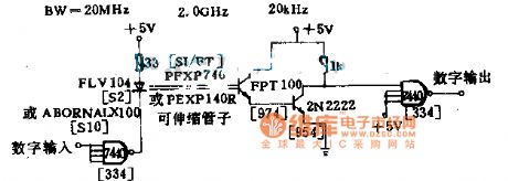
This is a demonstration circuit, the use of optical fiber cable and cheaper components, suitable for the applications of band narrower, teletypewriter signals feed to the distance to the microprocessor.
(View)
View full Circuit Diagram | Comments | Reading(906)
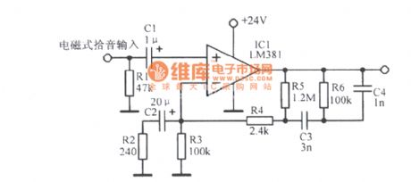
High fidelity preamplifier circuit diagram
Published:2014/1/6 19:46:00 Author: | Keyword: High fidelity preamplifier circuit diagram,
View full Circuit Diagram | Comments | Reading(1175)
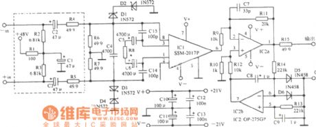
Audio low-noise preamplifier circuit diagram
Published:2014/1/6 19:45:00 Author: | Keyword: Audio low-noise preamplifier circuit diagram,
View full Circuit Diagram | Comments | Reading(1298)
XR1071 application circuit diagram
Published:2014/1/5 20:27:00 Author: | Keyword: XR1071 application circuit diagram, XR1071

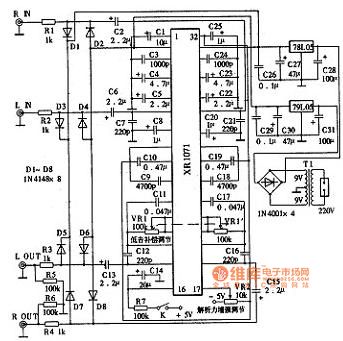
The practical application of the circuit XR1071 chip. Its performance is relatively good, signal-to-noise ratio as high as 95 db, total harmonic distortion, compensation adjustment range is bigger also, working voltage of + 5 v power supply, power consumption is only + 15 ma. VR2 for resolving power enhanced potentiometer, can make the own empowerment circuit after processing the audio signal analysis of the force, clarity from 0 dB to 9.7 dB. VR1 for low frequency component ascending potentiometer, adjusting range of 0 ~ 9.9 dB, improve low frequency in order to keep a good balance of high, medium and low frequency components. Adjust both to cooperate with each other, when the sound school to the state with the most natural and clear.
XR1071 application circuit diagram as shown
(View)
View full Circuit Diagram | Comments | Reading(1859)
BBE2150 application circuit diagram
Published:2014/1/2 20:25:00 Author: | Keyword: BBE2150 application circuit diagram, BBE2150
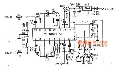
Bbe2150 application circuit diagram as shown (View)
View full Circuit Diagram | Comments | Reading(3927)
Shenlong fukang instrument system circuit diagram
Published:2013/12/25 19:30:00 Author: | Keyword: Shenlong fukang instrument system circuit diagram
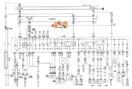
Shenlong fukang instrument system circuit diagram as shown below:
(View)
View full Circuit Diagram | Comments | Reading(913)
Shenlong fukang starting and charging system circuit diagram
Published:2013/12/25 19:28:00 Author: | Keyword: Shenlong fukang starting and charging system circuit diagram,
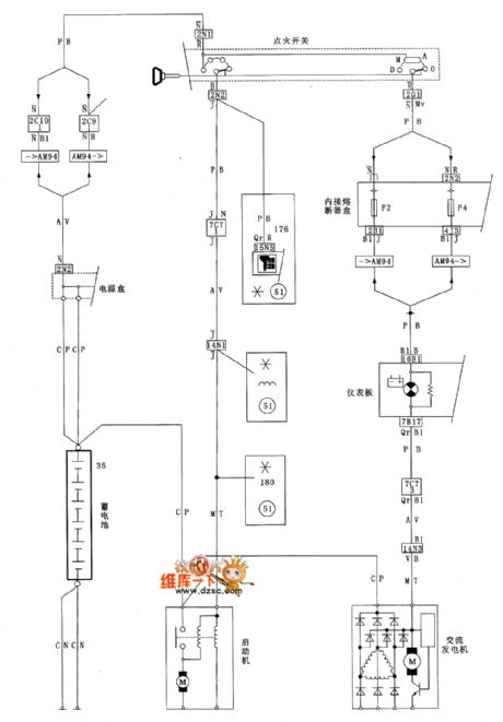
Shenlong fukang starting and charging system circuit diagram as shown below:
(View)
View full Circuit Diagram | Comments | Reading(815)
| Pages:3/195 1234567891011121314151617181920Under 20 |
Circuit Categories
power supply circuit
Amplifier Circuit
Basic Circuit
LED and Light Circuit
Sensor Circuit
Signal Processing
Electrical Equipment Circuit
Control Circuit
Remote Control Circuit
A/D-D/A Converter Circuit
Audio Circuit
Measuring and Test Circuit
Communication Circuit
Computer-Related Circuit
555 Circuit
Automotive Circuit
Repairing Circuit