
Signal Processing
Index 6
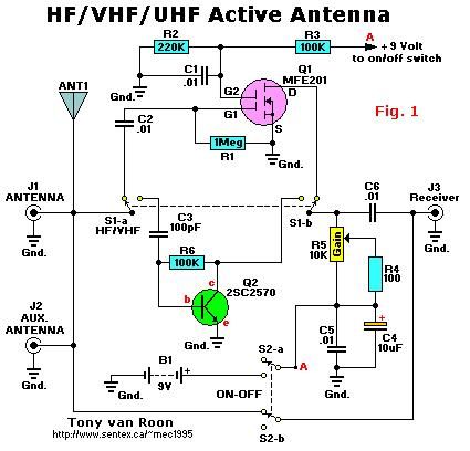
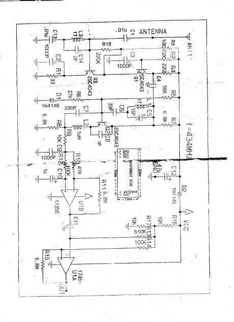
HF/VHF/UHF active antenna
Published:2013/7/15 0:59:00 Author:muriel | Keyword: HF/VHF/UHF , active antenna
View full Circuit Diagram | Comments | Reading(1425)
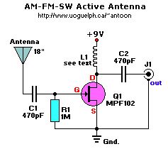
Active Antenna for AM/FM/SW 1
Published:2013/7/15 0:58:00 Author:muriel | Keyword: Active Antenna, AM/FM/SW
View full Circuit Diagram | Comments | Reading(1142)
5-Watt Transmitter
Published:2013/7/15 0:54:00 Author:muriel | Keyword: 5-Watt Transmitter
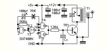
This is a very simple 5 watt CW TX based upon a TTL logic chip. There is just one tricky component and this is Cx. This component should have an impedance of about 10 - 50 ohms at the frequency of interest. If you wish to reduce the transmitter power, increase the value of Cx. It is Cx which causes the square wave from the output transistor to approximate a sine waveform. The value of Cx is the price of simplicity in this TX.
STARTING values for Cx are as follows (but there is a LOT of leeway)
1.8 MHz = 4.7nf
3.5 MHz = 2.2nf
7.0 MHz = 1.2nf
10 MHz = 820pf
14 MHz = 560pf
18 MHz = 470pf
24 MHz = 390pf
28 MHz = 330pf
It is far better to use too high a value for Cx initially then reduce it to achieve the correct RF output power. The value of Cx will depend upon your choice of TR1. Virtually any RF power transistor will work well in this application, as long as it will handle 800mA continuously. I have even used a BC108 in this application but the RF power was restricted to about 150mW. Cx was about 5x the value quoted above.
The output tuned circuit uses a coil WITHOUT ferrite slug. Use the usual rule-of-thumb formula for the tuned circuit;
Coil = Wavelength (in meters) = number of turns
Capacitor = Wavelength (in meters) = Capacitance (pf)
This will get you in the right area although it could differ widely with different coil formers. The coil output winding is from 5% to 15% of the total number of turns. Adjust the output winding before reducing the value of Cx. You need the least number of turns that will give you the power needed.
Connect +5 volts to the SN7400 chip and +12 volts to the PA and you will have over five watts of power out. To key the TX put the key in the +12v lead.
You MUST use an antenna LP-filter with this rig if you are using a good antenna. If the antenna is tuned (magnetic loop or frame antennas etc) then you need not bother with the LP-filter. Do NOT use a linear amplifier for this transmitter. The finished transmitter will fit into a matchbox with a little care.
I have received a comment from one constructor that if a 5-ohm resistor is fitted in the emitter of the transistor two things happen; 1. the output power increases, 2. It draws less current.
(View)
View full Circuit Diagram | Comments | Reading(0)
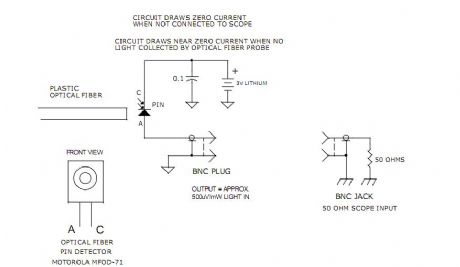
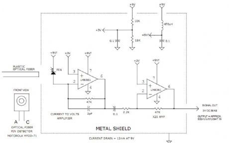
BROAD BAND 50MHz OPTICAL FIBER RECEIVER
Published:2013/7/15 0:46:00 Author:muriel | Keyword: BROAD BAND , 50MHz , OPTICAL, FIBER RECEIVER
View full Circuit Diagram | Comments | Reading(843)
BROAD BAND 2MHz OPTICAL FIBER RECEIVERS
Published:2013/7/15 0:44:00 Author:muriel | Keyword: BROAD BAND , 2MHz, OPTICAL FIBER RECEIVERS
View full Circuit Diagram | Comments | Reading(814)
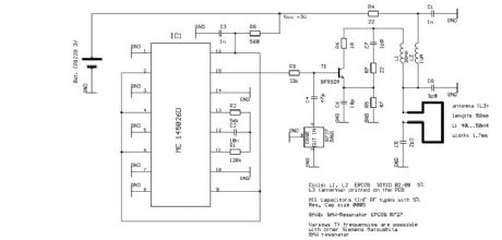
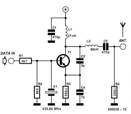
Remote-control transmitter for 433.92 MHz
Published:2013/7/11 22:40:00 Author:muriel | Keyword: Remote-control transmitter, 433.92 MHz
View full Circuit Diagram | Comments | Reading(4765)
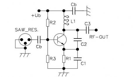
Pierce oscillator
Published:2013/7/11 22:39:00 Author:muriel | Keyword: Pierce oscillator
View full Circuit Diagram | Comments | Reading(3363)
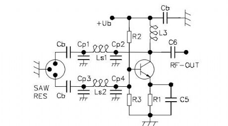
Colpitts oscillator with common base
Published:2013/7/11 22:39:00 Author:muriel | Keyword: Colpitts oscillator, common base
View full Circuit Diagram | Comments | Reading(2260)
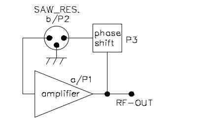
SAWR-based transmitters
Published:2013/7/11 22:38:00 Author:muriel | Keyword: SAWR-based transmitters
View full Circuit Diagram | Comments | Reading(865)
SAW-based transmitter design appnote from RFM 2
Published:2013/7/11 22:37:00 Author:muriel | Keyword: SAW-based transmitter

View full Circuit Diagram | Comments | Reading(1372)
SAW-based transmitter design appnote from RFM
Published:2013/7/11 22:37:00 Author:muriel | Keyword: SAW-based transmitter
View full Circuit Diagram | Comments | Reading(1601)
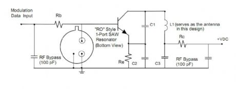
SAW-based 434MHz transmitter schematic with RO2101 (from appnote below)
Published:2013/7/11 22:36:00 Author:muriel | Keyword: SAW-based , 434MHz, transmitter schematic, RO2101

View full Circuit Diagram | Comments | Reading(3528)
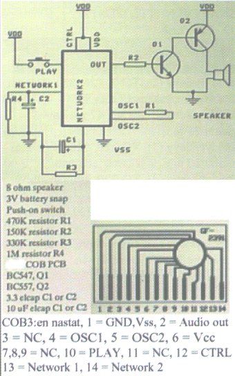
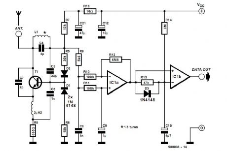
SP-Elektroniikka superregenerative receiver and SAW-based transmitter
Published:2013/7/11 22:35:00 Author:muriel | Keyword: SP-Elektroniikka, superregenerative, receiver , SAW-based transmitter
View full Circuit Diagram | Comments | Reading(904)
434MHz short-range communications 2
Published:2013/7/11 22:35:00 Author:muriel | Keyword: 434MHz , short-range communications
View full Circuit Diagram | Comments | Reading(1315)
434MHz short-range communications
Published:2013/7/11 22:34:00 Author:muriel | Keyword: 434MHz , short-range communications
View full Circuit Diagram | Comments | Reading(1547)
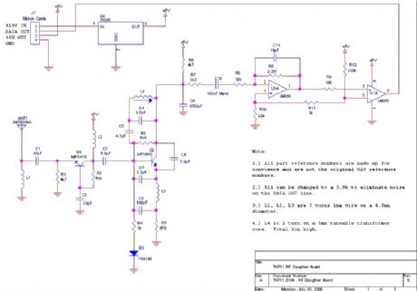
X10 RF daughter board - receiver
Published:2013/7/11 22:33:00 Author:muriel | Keyword: X10, RF , daughter board , receiver
View full Circuit Diagram | Comments | Reading(2664)
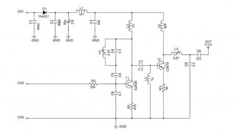
Automicro TM02 high power transmitter module schematic
Published:2013/7/11 22:32:00 Author:muriel | Keyword: Automicro, TM02, high power , transmitter module schematic
View full Circuit Diagram | Comments | Reading(1217)
Automicro RX3304receiver module photo
Published:2013/7/11 22:31:00 Author:muriel | Keyword: Automicro, RX3304, receiver module photo
View full Circuit Diagram | Comments | Reading(1095)
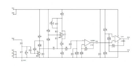
Automicro RX3302 superregenerative receiver module schematic
Published:2013/7/11 22:30:00 Author:muriel | Keyword: Automicro, RX3302 , superregenerative , receiver module schematic
View full Circuit Diagram | Comments | Reading(2512)
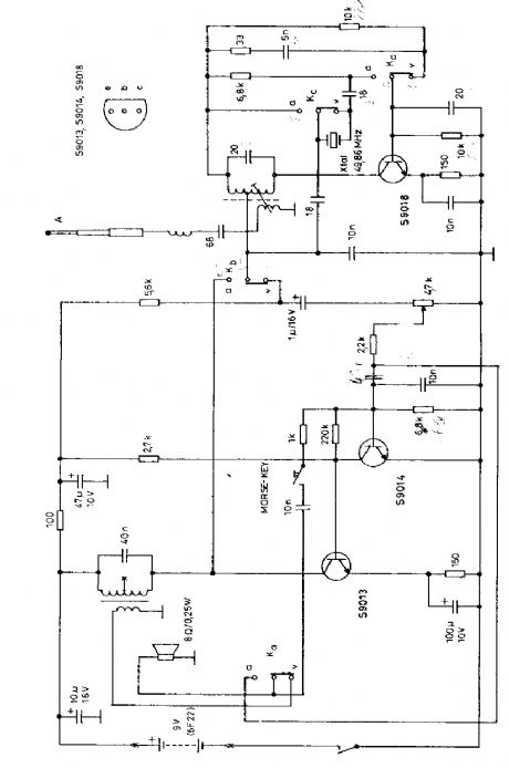
49MHz walkie-talkie schematic
Published:2013/7/11 22:30:00 Author:muriel | Keyword: 49MHz , walkie-talkie schematic
View full Circuit Diagram | Comments | Reading(2524)
| Pages:6/195 1234567891011121314151617181920Under 20 |
Circuit Categories
power supply circuit
Amplifier Circuit
Basic Circuit
LED and Light Circuit
Sensor Circuit
Signal Processing
Electrical Equipment Circuit
Control Circuit
Remote Control Circuit
A/D-D/A Converter Circuit
Audio Circuit
Measuring and Test Circuit
Communication Circuit
Computer-Related Circuit
555 Circuit
Automotive Circuit
Repairing Circuit