
Circuit Diagram
Index 1559
Typical half bridge type electric bicycle battery charger circuit
Published:2011/7/8 3:22:00 Author:Fiona | Keyword: Typical half bridge type, electric bicycle battery charger
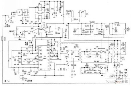
Discharge switch is a breakover of transistor Q6, Q6, its collector and emitter make the storage battery short out, storage battery discharges. Q6 is off, the storage battery restores charge.Q5 and Q6 aredirect coupling, commonly known as Darlington. Q6 is controlled by loading negative pulses and the oscillator. Loading negative pulse control is formed by the C and D of the IC3. D is connected as inverter ,only when the both inputs of C are high level, ③ pin is low level, it is opposite through the D to make the Q6 breakover to discharge for the storage battery.The ② feet of C comes from per second 1 (pulse width 3ms) positive pulse of the multivibrator ,the ① feet of C comes from the ① feet of two-phase current detection circuit IC2.When constant current is charging, ① pin is high level. At this point, the negative pulse is applied.
(View)
View full Circuit Diagram | Comments | Reading(4805)
practical lithium battery quick charger circuit
Published:2011/7/8 3:22:00 Author:Fiona | Keyword: practical lithium battery, quick charger
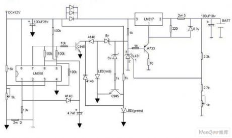
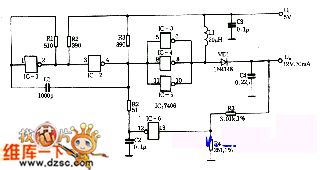
The circuit has a function of displaying the charging status.It is charging when the red light flashes and it will be full when the green light flashes, the green light means it is fully charged. As long as you have a 12V power supply, then do not replace the battery after completing the circuit, adjust the adjustable resistance at the lower right corner to make the battery output is 4.2V, and then adjust the adjustable resistance at the lower left corner to make the third pin of LM358 is 0.16V,and the charge current is 380mA, ultra-fast, three parallel diodes are used to step down and to prevent overheating LM317,and LM317 should add the heat sink, the transistor of the figure can be any type. (View)
View full Circuit Diagram | Comments | Reading(833)
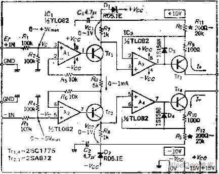
Good balance,wide selection of current balance constant current output circuit
Published:2011/7/8 3:21:00 Author:Fiona | Keyword: balance constant current output
Circuit Work
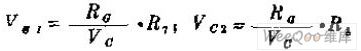
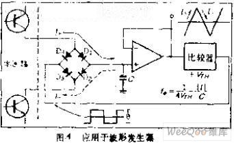
OP amplifiers A1 and A2 are to change the unipolar input circuit to a differential input circuit that the balance is good and change the 0 ~ 10V input to 0 ~ 1MA output (B = 10V, divided by R1, R2 , current is determined by the RO, RO = 5K, it is the resistance of the selected magnification), if R7 = R2, then the voltage generated at both ends of R7, R2 will be equal, namely:
If it is required to generate asymmetric waveform, as long as the R7 is not equal to R2, VC1 and VC2 can not be equal. It can also be used to generate the sawtooth.
OP mplifiers A3, A4 is a symmetrical circuit, respectively use +10 V and-10V as the base power, you can get I + = VC1/R11, I-= VC6/R12 constant current,change resistors R11 and R12's resistance or change V0 to do the current range switching.If R11 changes at 200Ω~2000Ωfor the unit with 10 times, VC1 = 1V, the circuit can get the constant current output that I + = 5MA, 500UA.
Figure A is the block diagram of unction generator waveform form part, the capacitor C is to constant current charge and discharge, it can produce a good linear triangular wave.
(View)
View full Circuit Diagram | Comments | Reading(1007)
Availability of IP / decimal output conversion circuit
Published:2011/7/8 3:21:00 Author:Fiona | Keyword: IP / decimal output

Circuit Work
As we all know,there exists logarithmic relationship between the transistor base very- occurs very voltage VBM and the collector current IO. Using this relationship can be made the log conversion circuit, the circuit principle expressed by the following relationship: IO1 and IO2 ratio is converted to logarithms, partial pressure ratio determines the constants,in order to make the change 10 times to obtain 1V output, according to [(R5 + R4) / R6] * 60 = 1000MV,it can get partial pressure ratio, the ratio value is 16.7. If R6 = 1K, then R4 = 15.7K, It adds ★ mark where the resistance is 1K at the circuit diagram, which means that in order to do the temperature compensation for transistor VBE, the resistance is thermistor which has a +3300 PPM / ℃ temperature characteristic. IC1 is the input current used for converting, reference current IC2 is supplied by the OP amplifier A2. (View)
View full Circuit Diagram | Comments | Reading(506)
consisting of TWH8751 lock control anti-theft alarm circuit
Published:2011/7/8 3:20:00 Author:Fiona | Keyword: lock control anti-theft alarm
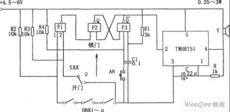
Figure shows the lock control anti-theft alarm circuit. The circuit consists of RS flip-flop, gated oscillator, the alarm circuit and so on.RS flip-flop consists of the NAND gate F2, F3, strobe oscillator consists of integrated circuits TWH8751 and R, C.
When the SKK is in the lock position, and the input 2 of NAND gate F1 is high, the state of DBK1-n is direct reflected by F1, if DBK1-n has an open circuit, the F1 output is low, RS flip-flop is set to 1 ,Choose the end (2) feet of the corresponding TWH8751 is low, trigger oscillator starts to oscillate, the oscillation signal makes the loudspeaker alarm.
(View)
View full Circuit Diagram | Comments | Reading(873)
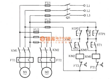
Two electric motors one after one start-up circuit
Published:2011/7/10 20:18:00 Author:John | Keyword: electric motor, motor, one after one start-up
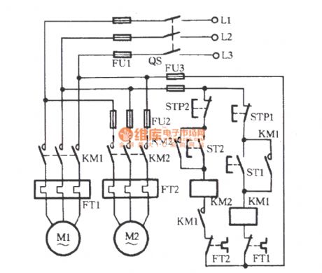
Procedures: Firstly, the starting button ST1 of the motor M1 is pressed to lead the KM1 coil to be energized. When the main contacts are closed, the motor M1 is launched to be self-locked. And the other pair of normally opening contact closes to induct the line circuit between KM2 and FT2. Then, press the starting button ST2 of the motor M2. The AC contactor KM2 would be powered to drive the electric motor M2 to start.
(View)
View full Circuit Diagram | Comments | Reading(2155)
DC boost circuit
Published:2011/7/10 19:36:00 Author:John | Keyword: DC boost
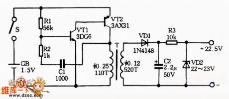
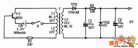
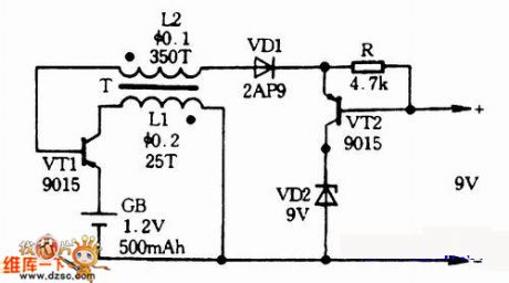
DC step-up is to upgrade the lower DC battery voltage to a required voltage. The basic work process is shown in the following: firstly the low-voltage pulse is throughhigh-frequency oscillation; then a predetermined voltage value is stepped-up by a pulse transformer; afterwards, high-voltage direct current is obtained by pulse rectifier. Thus, DC boost circuit is classified into DC / DC circuits.
In the portable battery-powered devices, the high voltage required in the circuit is usually obtained by DC boost circuits. These devices include cell phones, pagers, other wireless communications equipment, camera flash, portable video display device and power equipment such as electric shock and so forth.
(View)
View full Circuit Diagram | Comments | Reading(1717)
universal IF amplifier circuit
Published:2011/7/10 20:11:00 Author:John | Keyword: IF amplifier
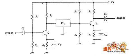
Crystal filters and mechanical filters all require specific coupling mechanism. The picture shows the coupling connection of the crystal filter which is between two bipolar transistors. Each level of the amplifier is a common emitter bipolar transistor amplifier. Bias voltage is set by the R1/R2 and R5/R6. And the connection to the filter circuit is direct, where the signal is not sensitive to the DC filter (thus this can not be called a mechanical filter). Figure shows another coupling connection, which is alternative both for mechanical filters and crystal filter.
(View)
View full Circuit Diagram | Comments | Reading(811)
LK001 selection frequency music outlet circuit
Published:2011/7/10 20:16:00 Author:John | Keyword: selection frequency music outlet

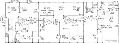
The circuit is as shown. It includes sound sensor BM, voice controlled IC, thyristor control circuit, imitation sound circuit and AC step-down rectifier circuit. Voice-specific integrated circuit LK001 is the core device of the circuit, whose internal function block circuit is shown.
(View)
View full Circuit Diagram | Comments | Reading(775)
Wire connection incandescent lamp life extension switch circuit
Published:2011/7/4 0:46:00 Author:John | Keyword: switch, incandescent lamp
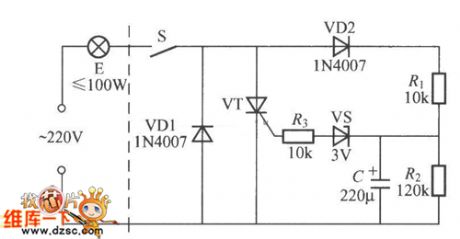
A wire connection incandescent lamp's life extension switch is shown. As its warm-up time is long, the service life of the bulb E is long. When the switch S is closed, 220V AC only has the negative half-cycle and powers bulb E through the VD1 and S. At this time, it is under the semi-pressure warm-up state. AC’s positive half-cycle charges the capacitor C through the VD2 and R1 and R2 divider until the voltage across C rises to more than 3V. Then the regulator thyristor VS is breakdown to conduct VT. Therefore, the bulb E is under total pressure to light.
(View)
View full Circuit Diagram | Comments | Reading(1006)
UPS instantly switching Y-△ starting circuit
Published:2011/7/10 20:20:00 Author:John | Keyword: KM4, Y-△ starting
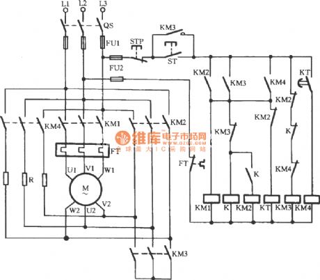
As for conventional Y-△ starting motors, when the motor shifts from a Y-shaped to △ running, phase short circuit often occur. In order to prevent phase short circuit, motor winding generator usually occur with power outages, thus inevitably for the formation of a strong secondary impact of current for the grid and the motor itself. The circuit is shown, which can achieve the uninterruptible power supply during the operation of shifting from Y-shaped to △ running. Besides, the voltage of the motor winding is not the line voltage which is directly from the Y-phase voltage to start operation of the △-shape. Actually, it has gone through a transition to an intermediate voltage level.
(View)
View full Circuit Diagram | Comments | Reading(1694)
zero sequence current protection with ultilizing third harmonic pressure velocity saturation circuit
Published:2011/7/10 20:19:00 Author:John | Keyword: current protection, third harmonic pressure velocity saturation

The shown circuit is suitable for △ or Y-shaped connection of the three-phase motor with rather great capacity. Off phase is to adopt a speed differential current transformer saturation TA, whose primary side is connected to the main circuit in series and secondary side’s head and tail is connected in series to form the open triangle. At the moment that the three-phase supply current (equal) is symmetrical, third harmonic voltage generated by TA is gone through the rectifier VC and the filtering capacitor C. So the sensitive K relay takes action to drive the motor M to run normally. When there is one phase is off, the remaining two-phase’s line current is with contrasting phase. And their synthetic current is zero for releasing the K and disconnecting the main circuit of the motor.
(View)
View full Circuit Diagram | Comments | Reading(1355)
two motors for sequential starting circuit
Published:2011/7/10 20:19:00 Author:John | Keyword: motor, sequential starting
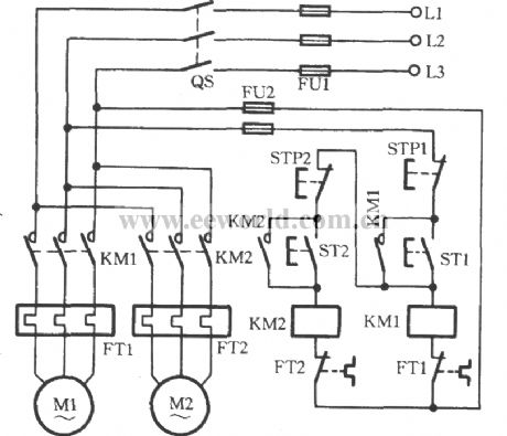
Some production machines have two or more electric motors, because these motor play different roles in the circuit. Sometimes, a certain sequence must be conformed to start in order, thus ensuring the normal production. The used circuit is shown in the figure. Take the two electric motors M1 and M2 used here for example. When the ST1 is pressed, KM1 coil is energized. And the coil’s main contacts and auxiliary contacts take action. And the motor M1 launches to be self-locked. It is obvious that KM1’s closure contact would not be self-locked if the ST2 is pressed firstly rather than the motor M1 (that is the ST1). Beside, KM2 coil would be in power shortage and be not able to start the motor M2.
(View)
View full Circuit Diagram | Comments | Reading(13776)
4-quadrant multiplication analog multiplication arithmetic circuit
Published:2011/7/8 3:20:00 Author:Fiona | Keyword: 4-quadrant multiplication, analog multiplication
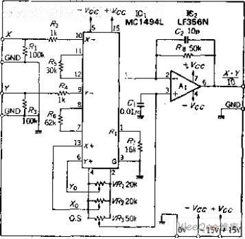

Circuit function
MC1494L is a monolithic analog multiplication IC composed of double-balanced differential amplifier, voltage - current converter circuit,a the general multiplication circuit which can use an external device to set the working conditions. It is capable of 4-quadrant multiplication and it is suitable of the various circuit which the input voltage is the positive and negative 10V.
Circuit work
In order to scale factor of 10, the resistances of resistors R5, R6 take 30K and 62K, lead terminal 14 is the collector output type.Owing to the current output,it adds the OP amplifier A1 to convert between current and voltage.The bias of IC1 output becomes the A1's positive input.
(View)
View full Circuit Diagram | Comments | Reading(1049)
two electric motors for sequential parking circuit
Published:2011/7/10 20:19:00 Author:John | Keyword: electric motor, sequential parking
In some working procedures, it is required to part the first motor and followed to park another motor. The figure shows the circuit of adapting to run the program. When the starting button ST1 is pressed, motor M1 operates. Then, the ST2 is pressed to pull KM2, leading to the operation of motor M2. Due to the KM2's pull, its normally opening contact is self-locked and the other contact closes to short the stop button STP1. Therefore, if the STP1 is pressed by mistake, KM1 will not lose power and release it. And the motor M1 will not stop at this time. Only the STP2 is pressed firstly to stop the motor M2 can the KM2 lose power. Then, its normally opening contacts release. Only under this situation can it is possible to stop M1 by pressing STP1.
(View)
View full Circuit Diagram | Comments | Reading(2355)
AM Monolithic Radio Circuit
Published:2011/7/9 2:43:00 Author:Joyce | Keyword: AM , Monolithic, Radio
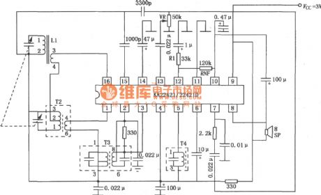
As shown in the circuit is a KA22421/22421D AM monolithic radio circuit. (View)
View full Circuit Diagram | Comments | Reading(1321)
High Q Band-pass Filter Circuit
Published:2011/7/9 10:56:00 Author:Joyce | Keyword: High Q , Band-pass , Filter
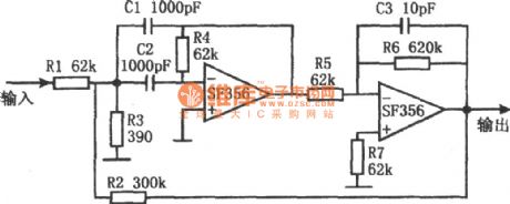
As shown in the figure is a high Q bandpass filter circuit. This circuit uses two operational amplifiers SF356 with high input impedance, of which the first stage working as a common single-section filter, whose Q value is low, the value of R3 is smaller, attenuation value is larger, and the magnification factor is small. But the magnification factor of the second stage inverse proportional amplifier is 10 times .And it will reach the input end of the first grade through R2 to introduce a certain amount of positive feedback, thus improving the Q value of the whole circuit. Therefore the filter has good frequency-selecting feature. (View)
View full Circuit Diagram | Comments | Reading(1934)
Simple and practical touch delay switch circuit
Published:2011/6/13 21:38:00 Author:Fiona | Keyword: Simple and practical, touch delay switch
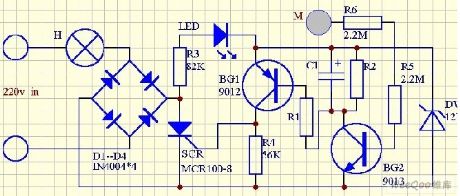
Delay switch circuit is shown in Figure D1 - D1, SCR component switch is composed of main circuit, BG1, BG2 switch and other components switches are composed of the control circuit. Switching delay time is mainly determined by the value of the resistance R1, R2 and capacitor C1. Provide a group of experimental data below for reference.If it want to further increase delay time, it can increase the capacity of C1. In addition to these major factors, BG1 magnification and the trigger sensitivity of the SCRare also affected to delay time. (View)
View full Circuit Diagram | Comments | Reading(1020)
Water towers water level controller circuit
Published:2011/7/8 3:23:00 Author:Fiona | Keyword: level controller
IC2 can use a variety of 555 time base integrated circuits. IC3 is the infrared receiver decoder CX20106A. IC4 can use 4N25, 4N26, PC817 and other optocoupler. Part of the infrared receiver can purchase finished infrared receiver components or integrated infrared receiver,it’s easy to produce and improve reliability. VD1, VD2 and VD3 can use infrared transmitter and receiver diodes of TVremote control. J chooses to use a new selection of memory self-locking relay,the shape of this relay is same as the general replay, the difference is that the pullis not required to maintain current,justwhen pulling and releasingit requires a certain pulse drive power, then the mechanical structure maintains locked state.
(View)
View full Circuit Diagram | Comments | Reading(1908)
A Simple Timer Circuit Composed of MC14541
Published:2011/7/9 2:06:00 Author:Joyce | Keyword: Simple, Timer
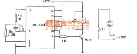
As shown in the figure is a simple timer circuit composed of MC14541, which is an integrated circuit. According to the parameters in the figure, its timing time is 3hours, and it can use different values of RTC、CTC and Rs to get various needed timing control .
(View)
View full Circuit Diagram | Comments | Reading(2971)
| Pages:1559/2234 At 2015411542154315441545154615471548154915501551155215531554155515561557155815591560Under 20 |
Circuit Categories
power supply circuit
Amplifier Circuit
Basic Circuit
LED and Light Circuit
Sensor Circuit
Signal Processing
Electrical Equipment Circuit
Control Circuit
Remote Control Circuit
A/D-D/A Converter Circuit
Audio Circuit
Measuring and Test Circuit
Communication Circuit
Computer-Related Circuit
555 Circuit
Automotive Circuit
Repairing Circuit