
Circuit Diagram
Index 1554
555 charging circuit used in the silver-cadmium battery
Published:2011/6/14 2:53:00 Author:nelly | Keyword: silver-cadmium battery, charging
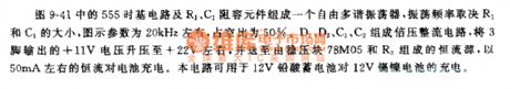
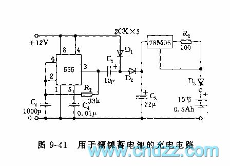
As shown on the figure 9-41, the 555 time base circuit and R1,C1 make up a freedom multivibrator. The oscillation frequency depends on the R1 and C1. The value is about 20KHz on the figure, the duty ratio is 50%. The voltage multiplying rectifier circuit consists of the D1,D2,C1,C2. Steping up the the 3 foot output voltage +11v to +12v and transporting to the constant current source which consists of the voltage stablizing unit 78M05 and R2. Using the constant current 50mA to charge the battery. This circuit can be used in that the 12v lead-acid battery charges the 12v Ni-Cd battery.
(View)
View full Circuit Diagram | Comments | Reading(1599)
555 high/low voltage monitor circuit 1
Published:2011/6/14 2:53:00 Author:nelly | Keyword: high/low voltage, monitor
As shown in the figure 9-17, the input voltage VDD is stabilized voltage supply, it requires hypotension outputs steady voltage, the load current reaches dozens of mA. The actable multivibrator is made of IC1 and R1, R2, C1, the oscillation frequency is f=1.44/ (R1+2R2)C1, generally speaking, the oscillation frequency should be about 10KHz. The pulse width modulator is composed of IC2 and R3, R4, C2, the filter smoothing circuit consists of L, C3, it makes the hgih duty ratio square wave smooth which is exported by IC2, the output voltage Vo is fed back and added to the control terminal of IC2, the width is modulated constantly.
(View)
View full Circuit Diagram | Comments | Reading(1445)
555 DC isolation converter circuit
Published:2011/6/14 2:53:00 Author:nelly | Keyword: DC isolation, converter
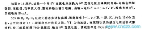
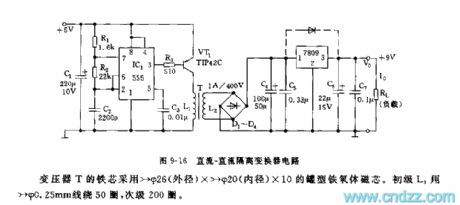
As shown on the figure 9-16, this is an isolation circuit that change the 5v DC voltage to the 9v DC voltage. The circuit includes an oscillator,a transformer, a power amplifier, rectifier and steady voltage output circuit. When the input voltage is between 4.5v and 5.5v, the output DC is 9v and the load current is 80mA. The actable multivibrator consists of the 555 and R1,R2,C2. The oscillation frequency: f=1.44/(R1+2R2)C2。It is about 15kHz, the duty ratio is close to 1:1. The VT1 is a power amplifier. The secondary transformer's induced voltage will output 9v DC voltage through the bridge rectifier and three terminal regulator. The full-efficiency can reach 65%.
(View)
View full Circuit Diagram | Comments | Reading(3837)
Electronic ballast comprehensive test instrument based on the MSP430F133
Published:2011/7/13 1:50:00 Author:TaoXi | Keyword: Electronic ballast, comprehensive, test instrument
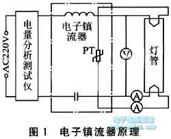
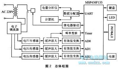
The electronic ballast principle is as shown in figure 1, the indexes that affect the electronic ballast's performance are: the preheat tube voltage of the start-up stage, the preheating filament current and preheating time, the stabilized lamp voltage, the lamp current, the oscillation frequency, the input current, the input power and the power factor, so we need to install the sensor to collector the lamp voltage of the output port, the filament current, the cathode circuit and the oscillation frequency, the power, current, power factor of the input port.etc.
(View)
View full Circuit Diagram | Comments | Reading(563)
Homemade maintenance and charging dual-function power supply circuit
Published:2011/7/13 4:53:00 Author:TaoXi | Keyword: Homemade, maintenance, charging, dual-function, power supply

Operating principle of the low voltage output: the 32V voltage of the transformer subprime stage is rectified by VD1-VD4 and filted by the C1, so we get the 45V DC voltage, this DC voltage changes into the stable output voltage through the integrated three-port voltage stabilizer LM338K, you can get the 1.25V-37V stable DC voltage from the output port by adjusting the potentiometer RP1. In the figure, the LED1 is the indicator light of the regulated power supply, R1 is the current-limiting resistance of LED1, C2 can be used to filter the high-frequency harmonic components of the power supply and eliminate the parasitic oscillation. The VD5 and VD6 can be used to prevent the input and output short circuits to protect the LM338K.
(View)
View full Circuit Diagram | Comments | Reading(989)
Storage battery automatic charger circuit (1)
Published:2011/7/13 19:17:00 Author:TaoXi | Keyword: Storage battery, automatic charger
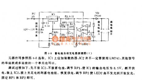
The circuit is as shown in figure 4-8. FU is the short circuit protection tube, LED1 is the power supply instruction, you can change the output voltage of IC1 by changing IC1, the center port of RP2 supplies the reference voltage to the positive phase input port of the voltage comparator IC2, R3 is the charge current sampling resistance, VD can be used to prevent the battery discharging, LED2 is the charging state instruction, C1 and C2 can be used to prevent the pulse interference.
The control principle of the stop-charging is: the charging current decreases with the charging process, and the voltage drop of R3 decreases too. If it is lower than the set value of RP2, the electrical level of pin-2 is lower than the electrical level of pin-3, pin-6 has the low electrical level, VD is in the reverse biasing state, the charging current is 0.
(View)
View full Circuit Diagram | Comments | Reading(916)
Storage battery automatic charger circuit (2)
Published:2011/7/13 19:28:00 Author:TaoXi | Keyword: Storage battery, automatic charger
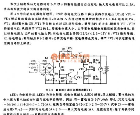
The principle diagram of the storage battery automatic charger circuit is as shown in the figure 4-9. The 220V city electricity is reduced by the transformer T to get the secondary voltage U2, and this secondary voltage U2 is bridge-type rectified to output the DC pulse voltage, the DC pulse voltage gets through the relay normally closed contact points K1-2,the R4, the ammeter PA, the VT1 and the battery GB, the VT2 to charge the GB. You can adjust the base potentials of VT1 and VT2 by adjusting RP1, so that you can adjust the Icb charging current of VT2. For example, when the battery voltage of the 12V storage battery increases to (12/2)X2.5=15V, VT3 conducts, K1 closes, the normally closed contact points K1-2 cut off to cut off the charging circuit, the charger will stop charging.
(View)
View full Circuit Diagram | Comments | Reading(821)
the circuit of the granary full reminder for the combine harvester (2)
Published:2011/7/8 7:34:00 Author:Ariel Wang | Keyword: granary full , reminder, combine harvester

When the granary is not full,the resistence of RC is low as it is irradiated by extraneous light.V1 is conducted.V2 is stopped.K is released.H1-2 aren't lighted.When the granary is full,the food shelters RC.the resistence of RC is large as it isn't irradiated by light.V1 is stopped.V2 is conducted.K is pulled in.The normally open contactors are connected.HL2 is lighted.HA gives out alarm sound.It informs the driver the granary is full. When at night,you should connect 51 as the extraneous light is too dim.Then HL1 is lighted.It prevents the alarm device from malfunction.
(View)
View full Circuit Diagram | Comments | Reading(492)
the fill light circuit of the chicken farm(2)
Published:2011/7/8 5:22:00 Author:Ariel Wang | Keyword: fill light, chicken farm
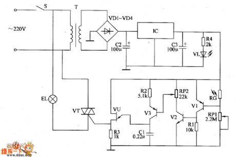
The 220V AC voltage is reduced by T,commutated by VD1~VD4,filtered by C2 and regulated IC.Then it becomes +9V voltage.It is the working power supply for the photometry circuit and the dimming circuit.At the same time,VL is lighted by R4.When in the daytime,the resistence of RC is low.V1~V3,VU and VT are stopped.EL isn't lighted.When in the cloudy and rainy day,the resistence of RC increases.V1~V3,VU and VT are all conducted.EL is lighted.The dimmer the light,the stronger the electric current,the faster of the C1's charging speed.The trigger pulse generated by VU increases the conduction angle of VT.And the brightness of EL becomes stronger.
(View)
View full Circuit Diagram | Comments | Reading(544)
the alarm circuit of the blocked seed channel in seeding-machine (1)
Published:2011/7/7 6:43:00 Author:Ariel Wang | Keyword: alarm , blocked , seed channel , seeding-machine
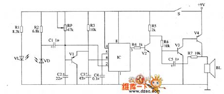
VL and VD are relatively set in the transmit seed tube.The infrared light which is emitted by V2 shines on VD.When seeding,if the transmit seed tube of the seeding-machine works right.The infrared light is sheltered by the seeds every now and then.The base electrode of V1 will generate a series continuous negtive pulse.V1 is conducted at a interval time.The pin-2 and pin-6 output low level.The pin-3 outputs high level.V2 is saturated to conduct.The audio oscillator consists of Y3,Y4,C5 and R7 stops oscillation.B1 doesn't give a sound.You can adjust the resistence of RP.It can change the action sensibility of the the trigger circuit. (View)
View full Circuit Diagram | Comments | Reading(504)
the controller circuit of the temperature(10)
Published:2011/7/7 6:51:00 Author:Ariel Wang | Keyword: controller, temperature
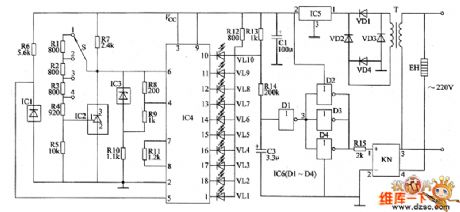
The 220V AC voltage is reduced by T,commutated by VD1~VD4,regulated by IC5,filtered by C1.It provides +9V working voltage for the temperature indicator circuit of LED and the control circuit of the heater.IC1 is the voltage-type positive temperature coefficient integrated temperature sensor.The sensibility is 10mV/℃.The output voltage is 2.73V when it's 0℃.The output voltage is 3.73V when it's 100℃.When the detected temperature changes,the output voltage of IC1 and the input voltage from the pin-5 of IC4 change synchronously. When it's processed by tenth voltage comparator in IC4,the drivers VL1~VL10 give out the light.It indicates the temperature value.
(View)
View full Circuit Diagram | Comments | Reading(564)
the alarm circuit for blocked fertilization tube of the seeding-machine
Published:2011/7/7 6:40:00 Author:Ariel Wang | Keyword: blocked, fertilization tube , seeding-machine
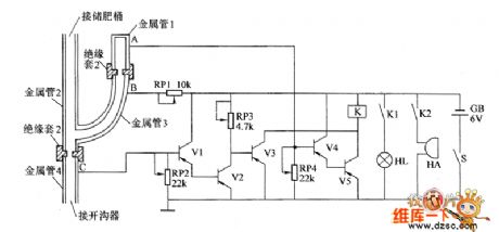
When you plant the crops and fertilize them,the liquid fertilizer in the fertilization storage tank goes to the ditching tube through the metal tube 2 and the metal tube 4.Then it goes to the soil.When the tube is unclogged,there is no liquid fertilizer in the metal tube 1.If there is liquid fertilizer in the metal tube 2 and 4,B and C is connected by the resistence of the liquid fertilizer.V1 and V2 are conducted.V3 is stopped.There are no liquid fertilizer in the metal tube 1 .It is insulated between A and B.So it is open-circuit between A and B.V4 and Y4 are stopped.K is released.HL is not lighted.HA doesn't give a sound. (View)
View full Circuit Diagram | Comments | Reading(509)
The joint circuit between MMA1260D and ATmega8L
Published:2011/7/7 6:39:00 Author:Ariel Wang | Keyword: joint, MMA1260D, ATmega8L
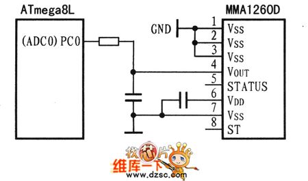
Acceleration sensor for MMA1260D collects the data of mobile acceleration. And it goes through the port of PC0 of ATmega8L(ADC0) to ATmega8L. It forms a direct ratio of the output voltage and the acceleration of MMA1260D's acceleration sensor. For measuring the output voltage of acceleration sensor,usually we use microcontroller with A/D. For specific connection,see chart. There is a filter between VOUT and the RC of A/DIN's pin.It is used for reducing the noise of the clock. There is no strong electric current between acceleration sensor and microcontroller.The 0.1μF capacitance between power-supply and ground is the decoupling capacitance. (View)
View full Circuit Diagram | Comments | Reading(664)
the circuit of the temperature controller(14)
Published:2011/6/28 8:11:00 Author:Ariel Wang | Keyword: temperature controller
RP is used to set the middle temperature.RT is used to detect the environment temperature.When the environment temperature is lower than the temperature set by RP,the resistence of RT increases.The pin-2 of IC1 outputs high level.Pin-12 and pin-11 output low level.VL2 and VL1 are lighted.It indicates the environment temperature is at a low level.At the same time,V1 is conducted.The relay K1 is conducted to pull in.The normally open contact is connected.The electric heater EH is conducted to work.It starts to heat.When the environment temperature rises to the temperature set by RP,the pin-11 of IC2 outputs high level.VL1 dies out.V1 is stopped.K1 is released.EH stops heating.At the same time,the pin-12 of IC1 outputs low level.VL2 is lighted.It indicates the environment temperature is the set temperature.
(View)
View full Circuit Diagram | Comments | Reading(468)
the circuit of the multifunctional protector for electric motor(1)
Published:2011/6/28 8:11:00 Author:Ariel Wang | Keyword: multifunctional protector , electric motor
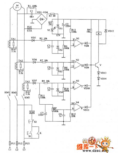
When 51 is pressed,the AC contactor KM is conducted to pull in.Three pairs of normally open contacts are connected.The electric motor M works.The AC voltage of L2 and L3 is reduced by C1,commutated by VD1~VD4,current limited by R3,regulated by VS1 and filtered by C2.Then it generates +12V voltage.It is for the control & protection circuit.At the same time,V1 is lighted.The +12V voltage is branched by R13 and R12.It provides reference voltage for inverting input ends of N1~N3 and non-inverting end of N4.TAI~TA3 are used to detect the two-phase power supply line of electric motor.And it generates 3 voltage signals for detect at R14~R16.
(View)
View full Circuit Diagram | Comments | Reading(519)
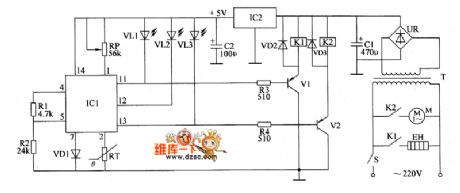
the circuit of the humidity controller(1)
Published:2011/7/7 6:28:00 Author:Ariel Wang | Keyword: humidity , controller
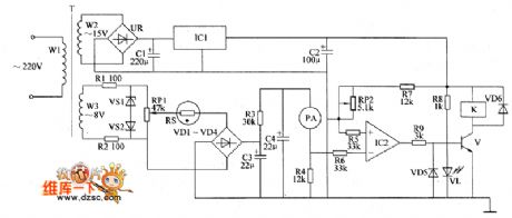
One part of the 220V AC voltage is reduced by T,commutated by UR,filtered by C1 and regulated by IC1.Then it generates +12V voltage for the humidity control circuit.At the same time,VL is lighted.The other part is reduced by T,current limitted by RI,regulated and clipped by VS2.Then it becomes flat-top AC voltage G.It is adjusted and sampled by RP1,reduced by RS and commutated by VD1~VD4.Then it becomes DC voltage.It is filted and current limitted by C2,R3 and CZ.Then it goes to the ammeter PA.The resistence of RS changes when the humidity changes.The environment humidty is higher,the resistence of ItS is lower.And the DC current passing through PA is larger.
(View)
View full Circuit Diagram | Comments | Reading(1754)
the circuit of the multifunctional protector for electric motor(4)
Published:2011/7/7 6:28:00 Author:Ariel Wang | Keyword: multifunctional protector, electric motor
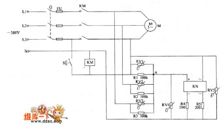
the working principle of the circuitSee as the chart above.The input voltage detecting circuit consists of the resistors RI~R3 and the varistors RV1~RV3.It is the balanced three phase circuit .When the three phase AC power supply is normal,the potential of the common point(A point) is 0V.When any phase of voltage in three phase AC power supply is abnormal(the voltage is too high or phase failure),the potencial of the common point rises.It conducts the in-circuit of the solid state relay KN.The coil in AC contactor KM is short-circuit.KM is released.It cuts off the input voltage.So it protects the electric motor. (View)
View full Circuit Diagram | Comments | Reading(461)
the circuit of the double hresholds temperature alertor(1)
Published:2011/7/7 6:49:00 Author:Ariel Wang | Keyword: double hresholds, temperature, alertor
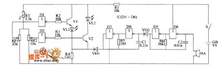
When the temperature is beyond the upper limit of the set temperature,the temperature of RT is decreased.The neutral pointpotential of RP1 is increased.D1 outputs low level.V1 is conducted.VL1 is lighted.It indicates the temperature beyond the upper limit.At the same time,VD1 is stopped.The 1Hz low-frequency oscillator and the 1kHz audiofrequency oscillator start to work.The 1Hz low-frequency oscillator modulates the 1kHz audiofrequency oscillator.HA gives out alam sound every now and then.When the temperature is lower than the lower limit of the set temperature,the resistence of RT is increased.The neutral point potential of RP2 is decreased.D2 outputs high level.1/2 is conducted.VL2 is lighted.It indicates the temperature is lower than the lower limit.At the same time,the 1Hz low-frequency oscillator and the 1kHz audiofrequency oscillator starts to work.HA give out alarm sound. (View)
View full Circuit Diagram | Comments | Reading(467)
the control circuit of electric fence part 6
Published:2011/6/13 7:04:00 Author:Ariel Wang | Keyword: control, electric, fence
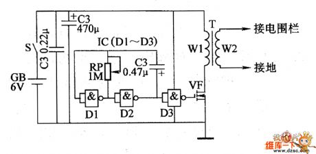
The impulsed voltage output circuit is composed by NAND gate in IC,field effect transistor VF and pulse transformer T.When the mains switch S gets through,the oscillator works.NAND gate D2 outputs oscillatory signal .It is buffered and processed by NAND gate D3 .Then it goes to the grid of VF.It conducts VE at interval time.It will generate about 200V impulsed voltage.It goes to the electric fence.It gives animals deterrence .You can adjust the resistence of RP,in order to change the working frequency of the oscillator.
(View)
View full Circuit Diagram | Comments | Reading(1069)
The circuit of download line for AT89S52
Published:2011/6/13 7:14:00 Author:Ariel Wang | Keyword: download line , AT89S52

By analysing parallel port and programming time sequence,we made ISP download cable of MCU for AT89S5X. We make a brief introduction of parallel port and the connecting line of ACU. The pin of the parallel port of P2 is connected to P1.5'spin(MOSI) of MCU .The parallel port P10's pin is connected to P1.6's pin of MCU(MISO). The parallel port P1's pin is connected to P1.7's pin of MCU(SCK). The parallel port P17's pin is connected to RST's pin of MCU. See the chart above.
(View)
View full Circuit Diagram | Comments | Reading(1756)
| Pages:1554/2234 At 2015411542154315441545154615471548154915501551155215531554155515561557155815591560Under 20 |
Circuit Categories
power supply circuit
Amplifier Circuit
Basic Circuit
LED and Light Circuit
Sensor Circuit
Signal Processing
Electrical Equipment Circuit
Control Circuit
Remote Control Circuit
A/D-D/A Converter Circuit
Audio Circuit
Measuring and Test Circuit
Communication Circuit
Computer-Related Circuit
555 Circuit
Automotive Circuit
Repairing Circuit