
Circuit Diagram
Index 2141
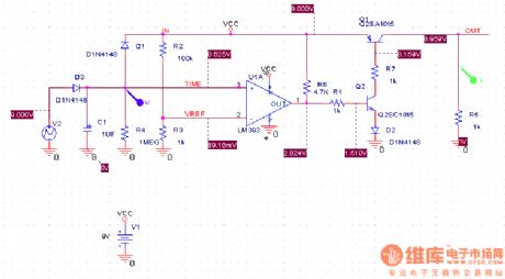
RF probe with negative pressure source circuit diagram
Published:2011/4/7 21:51:00 Author:Ecco | Keyword: RF probe , negative pressure source
View full Circuit Diagram | Comments | Reading(604)
Negative feedback superlinear amplifier circuit
Published:2011/4/7 22:22:00 Author:Ecco | Keyword: Negative feedback, superlinear amplifier
View full Circuit Diagram | Comments | Reading(749)
PWM controller of controlling DC power load circuit diagram and principle analysis(555 circuit)
Published:2011/4/7 21:35:00 Author:Ecco | Keyword: PWM controller, DC power load , principle analysis, 555 circuit
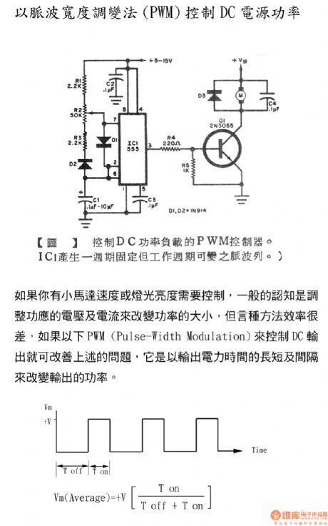
The pulse-width modulation (PWM) controlling DC Power
If you have to control small motor speed or light levels, the general perception is to adjust the supply voltage and current to change the power, but efficiency of this method is poor, if using the following PWM to adjust the DC output can improve the above problems. It is based on the length of the output power and the interval of time to change the output power.
(View)
View full Circuit Diagram | Comments | Reading(1900)
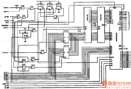
Synchronous access mode realization circuit diagram of liquid crystal display
Published:2011/4/7 21:47:00 Author:Ecco | Keyword: Synchronous access mode, liquid crystal display
View full Circuit Diagram | Comments | Reading(533)
Multimeter delay switch circuit diagram
Published:2011/4/7 3:06:00 Author:Ecco | Keyword: Multimeter , delay switch
View full Circuit Diagram | Comments | Reading(597)
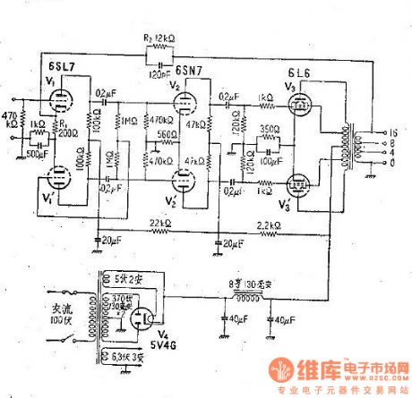
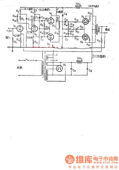
Williamson amplifier circuit diagram
Published:2011/4/7 22:23:00 Author:Ecco | Keyword: Williamson amplifier
View full Circuit Diagram | Comments | Reading(906)
The push-pull circuit diagram without output transformer
Published:2011/4/8 1:40:00 Author:Ecco | Keyword: push-pull circuit , without output transformer
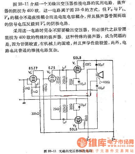
Figure 28-11 describes a practical circuit of push-pull circuit without output transformer. The impedance of speakers is 400Ω. The circuit is using the way of Figure 23-6, but the coupling between V0 and V1, V2 is not directly coupled but the coupling of the resistance and capacitance, and the signal voltage of loudspeaker is feedbacked to the cathode circuit of V0. The circuit doesn't need output transformer, but replaced by a special speaker with voice coil impedance in 400Ω. As the voice coil that is relatively heavy, so the problem is that there are mechanical difficulties, and the acoustic performance is poor, in addition, the push-pull circuit more complex than the normal.
(View)
View full Circuit Diagram | Comments | Reading(680)
Amplifier circuit diagram (with negative feedback)
Published:2011/4/8 0:59:00 Author:Ecco | Keyword: Amplifier circuit , negative feedback
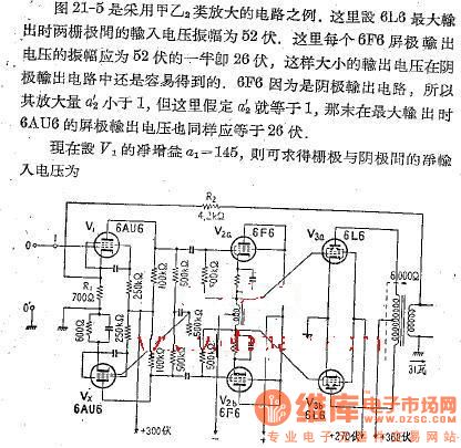
Figure 21-5 is an example of amplifier circuit using A,Ba. The maximum input voltage amplitude is 52V between two grids of 6L6. The output voltage of each 6F6 anode should be half of 52V, that is 28V, then the output voltage in cathode is easy to get. As 6F6 is cathode output circuit, the gain of a2 ' is less than 1. But if a2 ' is equal to 1, then the maximum output voltage 6AU6 is also equal to 26V. Now setting the gain a1 of V1 is equal to 145, you can find the net between the gate and the cathode input voltage. (View)
View full Circuit Diagram | Comments | Reading(1458)
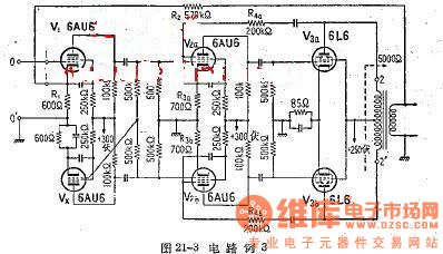
The push-pull amplifier circuit diagram 3
Published:2011/4/8 1:07:00 Author:Ecco | Keyword: push-pull amplifier
View full Circuit Diagram | Comments | Reading(878)
The push-pull amplifier circuit diagram 2
Published:2011/4/8 1:21:00 Author:Ecco | Keyword: push-pull amplifier
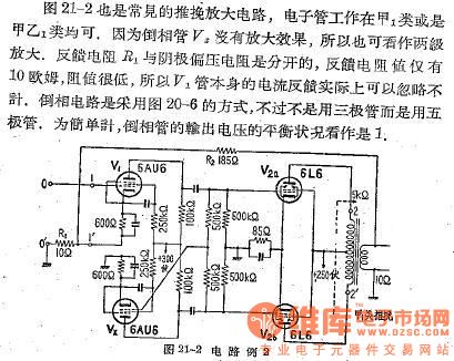
Figure 21-2 is a common push-pull amplifier circuit; And the tube can work in the class of A1 or AB1. As invert tube V2 has no amplification effect, it can be seen as polar amplification. Feedback resistor R1 is separate from the cathode bias resistor, the feedback resistance is only 10Ω, the resistance is very low, so the feedback current of V1 tube is negligible. Inverter circuit adopts the way of Figure 20-6, it does not use the transistor but use pentode, for simplicity, the balance of output voltage of the inverting tube is seen as 1.
(View)
View full Circuit Diagram | Comments | Reading(1110)
The push-pull amplifier circuit diagram 1
Published:2011/4/8 1:07:00 Author:Ecco | Keyword: push-pull amplifier
View full Circuit Diagram | Comments | Reading(762)
The basic form circuit diagram of serial input current feedback
Published:2011/4/8 2:01:00 Author:Ecco | Keyword: basic form , serial input, voltage feedback
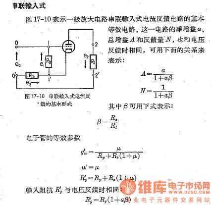
Figure 17-10 shows a basic equivalent circuit of serial input current feedback circuit in an amplifier circuit. The net gain of this circuit a, the total amount of gain A and feedback N, are the same with voltage feedback.
(View)
View full Circuit Diagram | Comments | Reading(530)
The basic form 2 of parallel input voltage feedback
Published:2011/4/8 1:55:00 Author:Ecco | Keyword: basic form , parallel input , voltage feedback
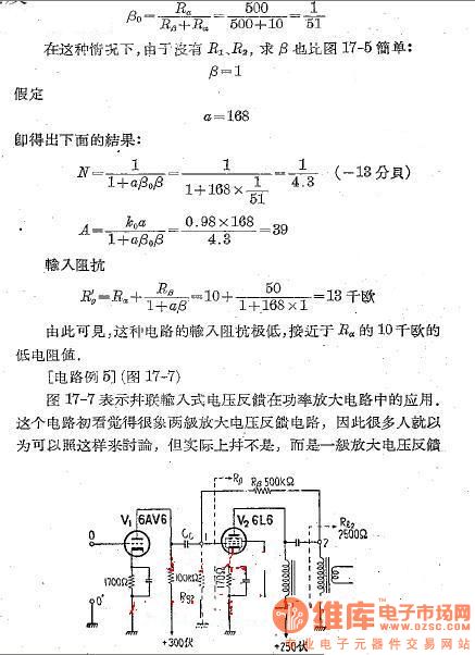
Figure 17-7 shows the applications of parallel input voltage feedback in power amplifier circuit.At first glance this circuit is like poles amplification voltage feedback circuit, so many people think they can be discussed according to this, but actually it's wrong, this is a pole amplification voltage feedback.
(View)
View full Circuit Diagram | Comments | Reading(459)
The basic form 1 of parallel input voltage feedback
Published:2011/4/8 1:46:00 Author:Ecco | Keyword: basic form, parallel input , voltage feedback
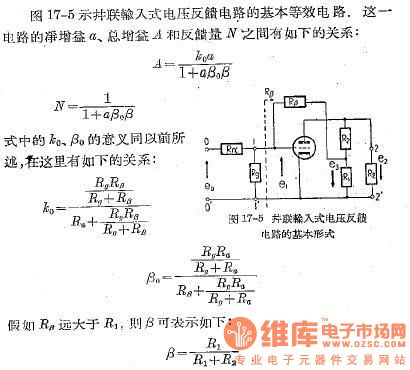
Figure 17-5 shows the the basic equivalent circuit of parallel input voltage feedback circuit.
(View)
View full Circuit Diagram | Comments | Reading(527)
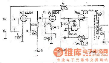
The amplifier circuit of electronic tube 6L6
Published:2011/4/8 2:15:00 Author:Ecco | Keyword: amplifier circuit , electronic tube

View full Circuit Diagram | Comments | Reading(1057)
Multi-level negative feedback circuit
Published:2011/4/8 2:13:00 Author:Ecco | Keyword: Multi-level, negative feedback
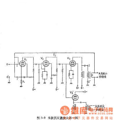
View full Circuit Diagram | Comments | Reading(618)
The display application circuit diagram of 74LS161 counter
Published:2011/4/8 2:12:00 Author:Ecco | Keyword: display application , counter
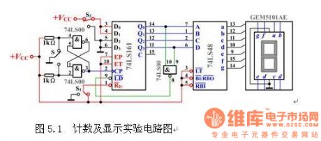
The display application circuit diagram of counter is as the chart 5.1
(View)
View full Circuit Diagram | Comments | Reading(4824)
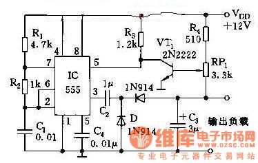
The alarm circuit controlling by intensity of usable light
Published:2011/4/8 2:33:00 Author:Ecco | Keyword: alarm circuit , controlling , intensity , usable light
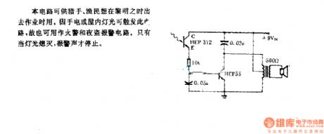
The circuit is available for hunters, fishermen when working at dawn, because the light from flashlights or inside can trigger circuit, it is also used as a fire and burglar alarm circuit. Only the lights are off, the alarm can stop.
(View)
View full Circuit Diagram | Comments | Reading(602)
Single pulse generator composed of CC4013 and CC4069
Published:2011/4/8 4:43:00 Author:Ecco | Keyword: Single pulse generator

View full Circuit Diagram | Comments | Reading(1024)
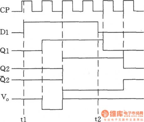
Simple adjustable duty cycle pulse generator
Published:2011/4/8 4:41:00 Author:Ecco | Keyword: Simple adjustable , duty cycle , pulse generator
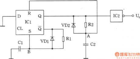
The pulse generator shown in the chartis composed of CMOS circuit and D trigger
(View)
View full Circuit Diagram | Comments | Reading(857)
| Pages:2141/2234 At 2021412142214321442145214621472148214921502151215221532154215521562157215821592160Under 20 |
Circuit Categories
power supply circuit
Amplifier Circuit
Basic Circuit
LED and Light Circuit
Sensor Circuit
Signal Processing
Electrical Equipment Circuit
Control Circuit
Remote Control Circuit
A/D-D/A Converter Circuit
Audio Circuit
Measuring and Test Circuit
Communication Circuit
Computer-Related Circuit
555 Circuit
Automotive Circuit
Repairing Circuit