
Circuit Diagram
Index 2150
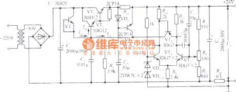
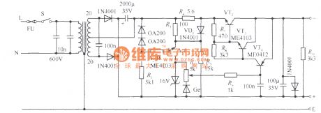
24V regulated power supply circuit with current compensation
Published:2011/4/7 1:56:00 Author:Nicole | Keyword: 24V regulated power supply, current compensation
View full Circuit Diagram | Comments | Reading(589)
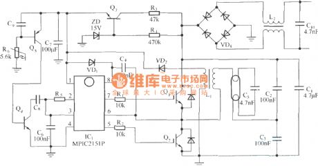
CFL electron ballast circuit composed of MPIC2151P and PowerLuxTM IGBT
Published:2011/4/2 3:25:00 Author:may | Keyword: electron ballast, PowerLuxTM IGBT
View full Circuit Diagram | Comments | Reading(1667)
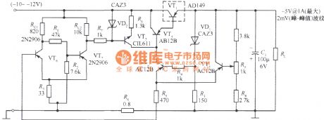
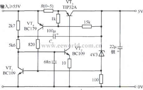
5V regulated power supply circuit with short circuit protection
Published:2011/4/7 1:57:00 Author:Nicole | Keyword: 5V regulated power supply, short circuit protection
View full Circuit Diagram | Comments | Reading(1979)
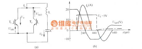
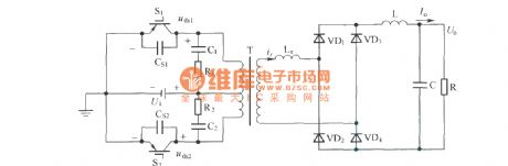
Reduced series resonant inverter main topological structure with resonance pole capacitor buffer
Published:2011/4/7 4:41:00 Author:may | Keyword: series resonant inverter, topological structure, resonance pole, capacitor buffer
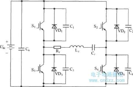
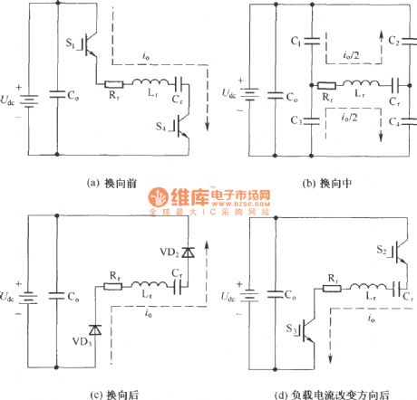
Series resonant inverter with resonance pole capacitor buffer’s process of changing current:
Routine RCVD buffer circuit adopts resistor to discharge, with the increase of switch frequency, the power consume in buffer is increase too, greatly reduce the efficiency of the whole inverter system. It can effectively reduce the shutoff loss of switch device that directly parallel connect a non-loss buffer capacitor between IGBT collector and emitter. It is more fit for high frequency inverter to feedback the power of the resistor loss in routine buffer to load or power supply.
(View)
View full Circuit Diagram | Comments | Reading(3551)
5V regulated power supply circuit with over cut protection
Published:2011/4/7 1:59:00 Author:Nicole | Keyword: 5V regulated power supply, over cut protection
View full Circuit Diagram | Comments | Reading(805)
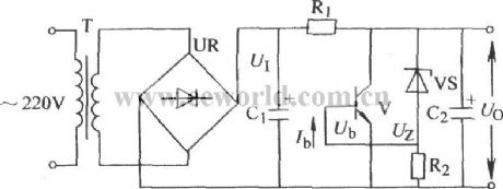
Steady voltage circuit with overcurrent protection
Published:2011/4/7 2:01:00 Author:Nicole | Keyword: steady voltage, overcurrent protection
View full Circuit Diagram | Comments | Reading(562)
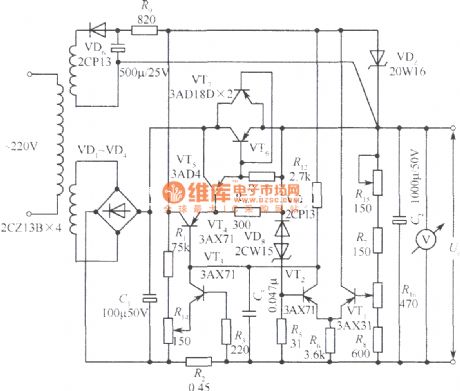
24V regulated power supply circuit with current limiting protection
Published:2011/4/7 2:06:00 Author:Nicole | Keyword: 24V regulated power supply, current limiting protection
View full Circuit Diagram | Comments | Reading(2076)
0~15V regulated power supply circuit with current limiting protection
Published:2011/4/7 2:07:00 Author:Nicole | Keyword: 0~15V regulated power supply, current limiting protection
View full Circuit Diagram | Comments | Reading(941)
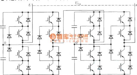
Single-phase topological structure of cascade connection multilevel inverter basing on star point clamp type
Published:2011/4/7 4:23:00 Author:may | Keyword: Single-phase topological structure, cascade connection, multilevel inverter, star point clamp type
View full Circuit Diagram | Comments | Reading(2221)
High voltage frequency conversion power supply
Published:2011/4/7 4:18:00 Author:may | Keyword: High voltage, frequency conversion, power supply
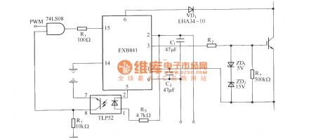
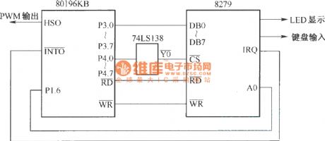
The main circuit of high voltage frequency conversion power supply adopts alternate-direct-alternate voltage type circuit. Bridge type inverter circuit consists of high power full control type power electronic device IGBT. The control circuit uses pulse width (PWM) technology and SCM (80196KB) control technology.
1, IGBT drive circuit
2, control circuit block diagram:
(View)
View full Circuit Diagram | Comments | Reading(1726)
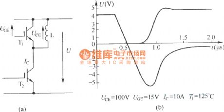
IGBT shut off voltage wave and chopper circuit in advanced hard switching chopper circuit
Published:2011/4/7 4:05:00 Author:may | Keyword: IGBT shut off voltage wave, chopper, hard switching chopper
View full Circuit Diagram | Comments | Reading(865)
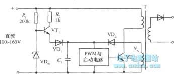
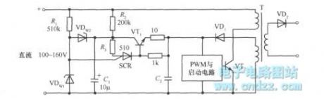
Practical soft-start circuit in switching power supply
Published:2011/4/7 2:22:00 Author:Nicole | Keyword: soft-start, switching power supply
View full Circuit Diagram | Comments | Reading(744)
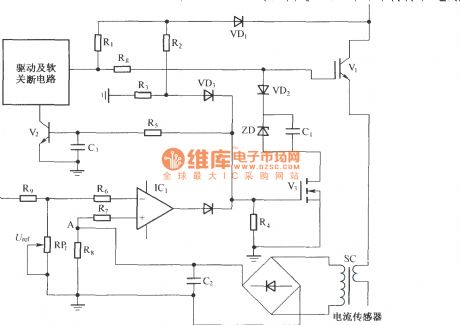
Integrated protection circuit with UCE increasing in IGBT short cut and current sensor detection
Published:2011/4/2 3:38:00 Author:may | Keyword: Integrated protection, UCE enlarging, IGBT short cut, current sensor detection
View full Circuit Diagram | Comments | Reading(1314)
The circuit and shutoff wave in two reverse blocking type IGBT reverse parallel connection
Published:2011/4/7 4:05:00 Author:may | Keyword: reverse blocking type, IGBT, reverse parallel connection, shutoff wave
View full Circuit Diagram | Comments | Reading(570)
The package of Mitsubishi IPM
Published:2011/4/7 20:48:00 Author:may | Keyword: Mitsubishi,
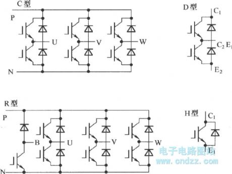
IPM is advanced hybrid integrated power device. It is integrated high-speed, low power consumption IGBT chip and optimal grid drive circuit and kinds of protective circuit in one module. Compare to ordinary IGBT, IPM has further increase in system features and reliability. Also, because its conduction losses and switch losses is quite low, the size of radiator is small, so size of the whole system is more small. Moreover IPM internal integrated logic, control, detect ion and protect circuit, the use is convenient, it not only decrease the volume of this system and the development time, also greatly add reliability of the system. (View)
View full Circuit Diagram | Comments | Reading(1262)
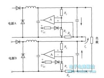
Fault prevention ways with two power series(using フ current protection circuit)
Published:2011/4/7 2:35:00 Author:Nicole | Keyword: fault prevention way, two power
View full Circuit Diagram | Comments | Reading(742)
Soft switching schematic circuit diagram
Published:2011/4/2 3:52:00 Author:may | Keyword: soft switching
View full Circuit Diagram | Comments | Reading(781)
Zero-voltage zero-current switch three-level DC converter
Published:2011/4/7 20:34:00 Author:may | Keyword: zero-voltage zero-current switch, three-level DC converter
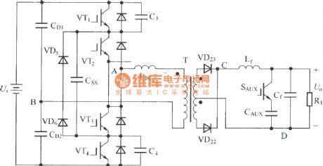
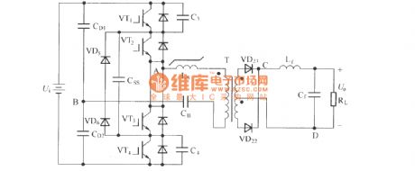
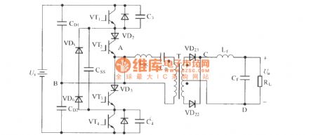
In order to remove circulating current of zero-voltage switch three-level DC converter in zero state, we come up with kind of zero-voltage zero-current switch three-level DC converter circuit. The circuit is shown in the following diagram
1, the main difference between this circuit and zero-voltage switch three-level DC converter is: add coupling capacitance C55 and add pilot switch SAUX and clamp capacitance CAUX in transformer secondary winding; coupling capacitance C55 separately connect the switch process of outer outer-side tube VT1, VT4 and in side tube VT2, VT3.
2, this circuit adopts blocking capacitor as blocking voltage source, let transformer once side current decrease to zero in zero state, thereby achieve zero current switch of in side switch tube.
3, This diagram separately series diode VT2 and VT3 in branch circuit of VT2 and VT3 in order to prevent the transformer once side current to continue flow in negative direction in zero state. It removes the minus effect after adding saturated inductance.
(View)
View full Circuit Diagram | Comments | Reading(2238)
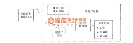
Lithium ion battery charging and system load power up schematic diagram
Published:2011/4/7 2:39:00 Author:Nicole | Keyword: lithium ion battery, charging, system load
View full Circuit Diagram | Comments | Reading(960)
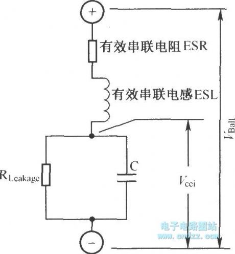
Lithium ion battery equivalent circuit
Published:2011/4/7 3:01:00 Author:Nicole | Keyword: lithium ion battery
View full Circuit Diagram | Comments | Reading(1147)
| Pages:2150/2234 At 2021412142214321442145214621472148214921502151215221532154215521562157215821592160Under 20 |
Circuit Categories
power supply circuit
Amplifier Circuit
Basic Circuit
LED and Light Circuit
Sensor Circuit
Signal Processing
Electrical Equipment Circuit
Control Circuit
Remote Control Circuit
A/D-D/A Converter Circuit
Audio Circuit
Measuring and Test Circuit
Communication Circuit
Computer-Related Circuit
555 Circuit
Automotive Circuit
Repairing Circuit