
Circuit Diagram
Index 2142
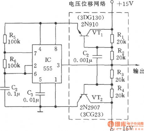
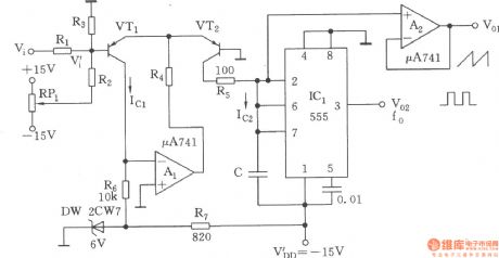
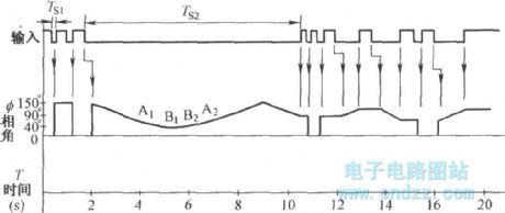
Zero-symmetric bi-directional pulse generator
Published:2011/4/8 3:02:00 Author:Ecco | Keyword: Zero-symmetric , bi-directional , pulse generator
View full Circuit Diagram | Comments | Reading(727)
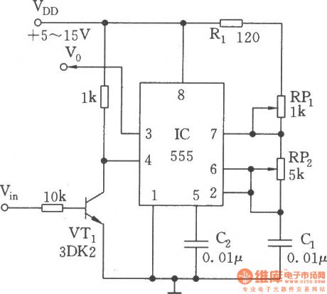
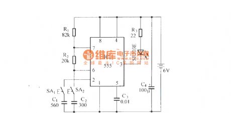
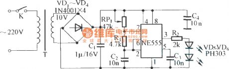
Gate pulse generator (555)
Published:2011/4/8 4:46:00 Author:Ecco | Keyword: Gate pulse generator , 555
View full Circuit Diagram | Comments | Reading(963)
Modulation optical receiving circuit
Published:2011/4/8 0:59:00 Author:Nicole | Keyword: optical receiving
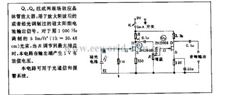
Q1, Q2 form two-stage FET amplifier, it is used in Si solar cells output singal after scale up chopper or optical modulation. About 1000Hz modulation 5lm/ft2(lft=30.48cm)light beam, when R is altered to the maximum gain, the circuit will produce 1V effective value voltage in output terminal.
This circuit can be used to optical communication and alarm system. (View)
View full Circuit Diagram | Comments | Reading(558)
Wideband VCO composed of CD4007
Published:2011/4/8 2:59:00 Author:Ecco | Keyword: Wideband , VCO
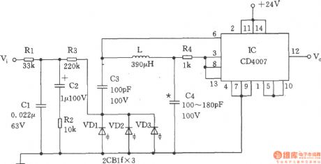
The VCO is shown as the chart. The voltage-controlled signal Vi provides a DC voltage with the changing of frequency and phase to the varactor VDl ~ VD3 and from the low-pass filter Rl ~ R3. The voltage is decided by the VCO (voltage controlled oscillator) output frequency of the inductor L, capacitor C3, C4 and varactor diode VDl ~ VD3 and IC (CD4007). (View)
View full Circuit Diagram | Comments | Reading(3652)
The principle diagram of radio-controlled car(the principle diagram of emitter)
Published:2011/4/8 2:18:00 Author:Ecco | Keyword: principle diagram, radio-controlled car, emitter
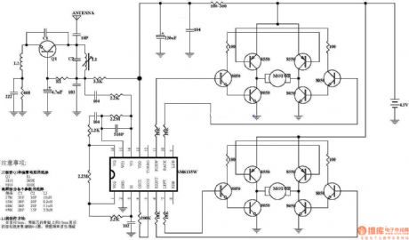
View full Circuit Diagram | Comments | Reading(1817)
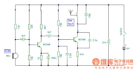
fm emitter circuit diagram
Published:2011/4/8 2:22:00 Author:Ecco | Keyword: fm , emitter
View full Circuit Diagram | Comments | Reading(806)
Wideband VCO composed of CD4046
Published:2011/4/8 2:52:00 Author:Ecco | Keyword: Wideband , VCO
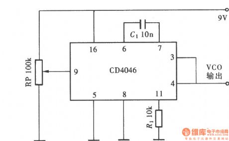
View full Circuit Diagram | Comments | Reading(3821)
The voltage-controlled oscillator(NE566V) with controlled wide range
Published:2011/4/8 2:50:00 Author:Ecco | Keyword: voltage-controlled oscillator, controlled wide range
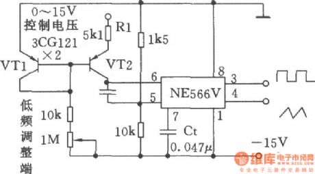
View full Circuit Diagram | Comments | Reading(581)
The voltage-controlled oscillator circuit(555) with logarithmic characteristic
Published:2011/4/8 2:47:00 Author:Ecco | Keyword: voltage-controlled oscillator , circuit logarithmic characteristic , 555
View full Circuit Diagram | Comments | Reading(950)
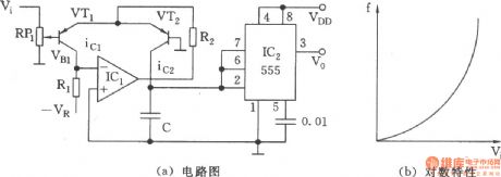
Exponential voltage-controlled oscillator(555)
Published:2011/4/8 2:46:00 Author:Ecco | Keyword: Exponential, voltage-controlled oscillator, 555

View full Circuit Diagram | Comments | Reading(2523)
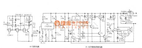
Infrared volume remote control circuit diagram
Published:2011/4/8 1:57:00 Author:Rebekka | Keyword: Infrared volume remote control
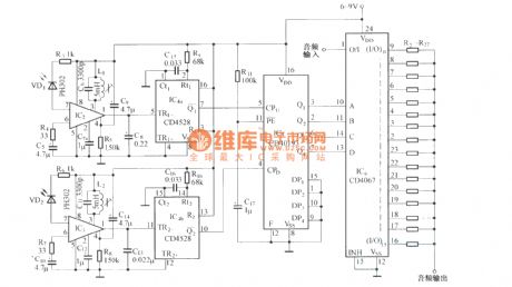
Dual-channel infrared transmitter:
(View)
View full Circuit Diagram | Comments | Reading(2469)
Infrared remote control color lamp circuit diagram
Published:2011/4/8 1:54:00 Author:Rebekka | Keyword: Infrared remote control color lamp
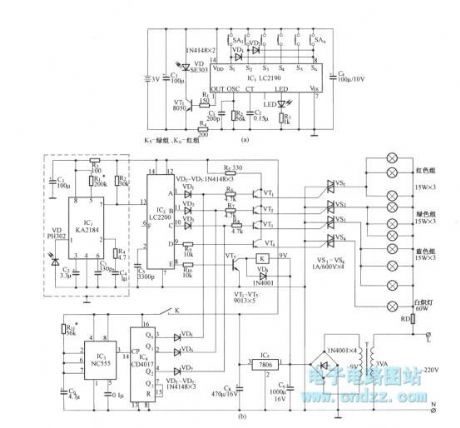
Figure (a) is six-way infrared remote control transmitter.
Figure (B) is infrared receiver demodulation, channel decoding circuit, lighting drive circuit.
(View)
View full Circuit Diagram | Comments | Reading(798)
CD4013 and CD4514 pin permutation circuit diagram
Published:2011/4/8 2:53:00 Author:Rebekka | Keyword: pin permutation
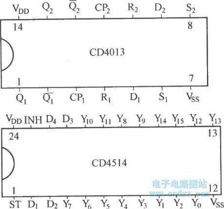
CD4514 is a four-sixteen line decoder.CD4013 is a bistable circuits.
(View)
View full Circuit Diagram | Comments | Reading(2346)
Infrared detection language alarm circuit diagram
Published:2011/4/8 1:51:00 Author:Rebekka | Keyword: Infrared detection language alarm
Infrared transmitter circuit is shown as below:
(View)
View full Circuit Diagram | Comments | Reading(669)
Infrared remote control multiway switch controllor circuit diagram
Published:2011/4/8 1:49:00 Author:Rebekka | Keyword: Infrared remote control, multiway switch controllor
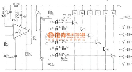
The circuit is composed of infrared receiver demodulation circuit and channel decoding circuit. μPC1373 is integrated infrared signal demodulation circuit. (View)
View full Circuit Diagram | Comments | Reading(845)
Infrared remote control multi-relay control switch circuit diagram
Published:2011/4/8 1:44:00 Author:Rebekka | Keyword: multi-relay control switch , Infrared remote control
View full Circuit Diagram | Comments | Reading(1434)
Infrared remote control voltage circuit diagram
Published:2011/4/8 1:42:00 Author:Rebekka | Keyword: Infrared remote control voltage
View full Circuit Diagram | Comments | Reading(575)
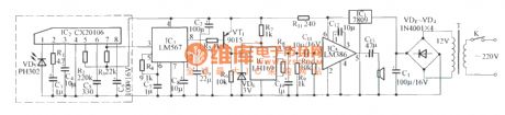
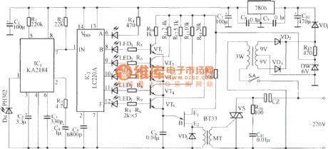
IR remote control dimmer circuit diagram
Published:2011/4/8 1:41:00 Author:Rebekka | Keyword: IR remote control dimmer
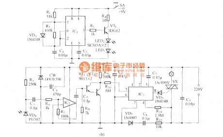
Infrared remote control transmitter diagram:
Infrared remote control receiver power amplification and dimming control circuit.
IC1 in IR emitter uses NE555, LM555 etc., IC2 can use μA741 or LM324. IC3 can use LS7232, can also be uses CS7232, SM7232, etc.
(View)
View full Circuit Diagram | Comments | Reading(2898)
Infrared remote control fan power supply outlet circuit diagram
Published:2011/4/8 1:36:00 Author:Rebekka | Keyword: Infrared remote control fan, power supply outlet
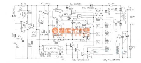
The circuit consists of infrared receiver demodulation circuit, speed control circuit, SCR phase trigger circuit and natural air control circuit. (View)
View full Circuit Diagram | Comments | Reading(1920)
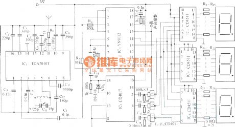
Frequency modulation radio reception main frame circuit diagram
Published:2011/4/8 2:05:00 Author:Rebekka | Keyword: Frequency modulation , radio reception main frame
View full Circuit Diagram | Comments | Reading(689)
| Pages:2142/2234 At 2021412142214321442145214621472148214921502151215221532154215521562157215821592160Under 20 |
Circuit Categories
power supply circuit
Amplifier Circuit
Basic Circuit
LED and Light Circuit
Sensor Circuit
Signal Processing
Electrical Equipment Circuit
Control Circuit
Remote Control Circuit
A/D-D/A Converter Circuit
Audio Circuit
Measuring and Test Circuit
Communication Circuit
Computer-Related Circuit
555 Circuit
Automotive Circuit
Repairing Circuit