
Circuit Diagram
Index 280
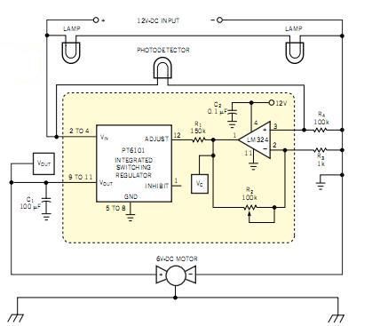
Switching regulator drives robot motor
Published:2012/11/9 20:24:00 Author:muriel | Keyword: Switching regulator, robot motor
View full Circuit Diagram | Comments | Reading(883)
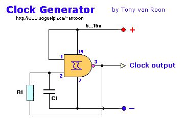
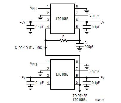
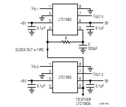
clock generator
Published:2012/11/9 20:22:00 Author:muriel | Keyword: clock generator
View full Circuit Diagram | Comments | Reading(1670)
IR slotted switch sensor
Published:2012/11/9 0:32:00 Author:muriel | Keyword: IR slotted switch, sensor
There is a type of detector known as a slotted switch that consists of a phototransistor/LED pair mounted on a solid frame with a small air gap between the two elements. A typical circuit might be:
o +5v o +5v
| |
| |
\ \
220 ohms / / 4.7K
\ \
/ /
| |
| +-------> Vout
_|_ /
\ / |/
----- |\ NPN
| \
| |
| |
| |
GND GND
| air gap |
When the air gap is unobstructed, the transistor saturates, pulling Vout to ground; when the gap is blocked, the transistor cuts off and Vout is +5 volts. (View)
View full Circuit Diagram | Comments | Reading(1305)
Minimizing SUN's noise in IR reception
Published:2012/11/9 0:31:00 Author:muriel | Keyword: Minimizing , SUNs noise , IR reception
A 'baffle' is a perforated disk or disks spaced inside your 'shade tube'. The idea is to trap all reflections, leaving only the light coming in on the exact axis of the tube to strike the IR Detector.
__________________________________
| | | |
DET <--- IR LIGHT
| | | |
----------------------------------
^Baff ^Baff ^Baff
Off-axis light, 'noise', will be caught by the baffles and dissipated through reflection between the baffles. Paint the inside of your tube black ... in fact, check into what paints/coatings are 'black' to IR wavelenghts. Just because a paint LOOKS black does not mean it won't reflect IR.
Check into an astronomy or optics group to get the formula for the ideal spacing of the baffles and how big a hole should be in them. Getting this right will improve your system performance. (View)
View full Circuit Diagram | Comments | Reading(694)
A very STABLE 40khz generator
Published:2012/11/9 0:31:00 Author:muriel | Keyword: A very STABLE, 40khz, generator
A circuit that I have used before is based on the CD4060 (14stage binary counter) and a 640Khz ceramic resonator. The CD4060 is basically an oscillator and a ripple counter to divide the 640khz down to something more usable.
Here is the pinout of the CD4060 (frequencies are assuming a 640khz input signal into pins 10/11/12 - circuit shown below):
+-\/-+
160hz 1 | | 16 Vcc
80hz 2 | | 15 625hz
40hz 3 | | 14 2.5khz
10khz 4 | | 13 125hz
20khz 5 | | 12 \
5khz 6 | | 11 >---- see sub-circuit below
40khz 7 | | 10 /
GND 8 | | 9 NC
+----+
Sub-circuit for a 640khz ceramic resonator:
12 >----------------------+
740pf | (you may be able to obtain
11 >-------+----+---|(----+ a resonator with builtin
| | | capacitors and three leads)
640khz --- \ |
res. O / 1Mohm |
--- \ |
| | |
10 >-------+----+---|(----+
740pf |
GND >----------------------+
A nice part about this circuit is that it delivers a STABLE 40khz signal, as well as delivering several other frequencies that can be used to modulate the 40khz carrier. For example, the person that designed this circuit (Ken Boone, member of Triangle Amateur Robotics) used it to build several beacons in his yard to serve as navigation points for a robotic lawnmower. By diode-OR'ing the results of the 40khz carrier and one of the lower frequencies (such as the 125Hz) line to drive a ring of IR-LEDs, he could locate the beacon and tell which, of several, beacons he had found.
This circuit has proven to be VERY stable, and is fairly inexpensive (about $1.50 for the CD4060 and 640Khz ceramic resonator). (View)
View full Circuit Diagram | Comments | Reading(1009)
Cheap 40KHz clock
Published:2012/11/9 0:30:00 Author:muriel | Keyword: Cheap , 40KHz , clock
Use a 40KHz Xtal and a 74C14 schmitt trigger:
________ <---------------- 2.2 M resistor
___| 2M2 |___
| |________| |
| |
| |
| |\ |
| | \ |
+-----| O------+--------> Output 40KHz
| | /
| |/ gate 1 of 74C14
|
|
--+--
XXX 40KHz Xtal
--+--
|
|
-----
---
-
This circuit has worked for me in many applications. (it might be an idea to buffer the signal befor using it. (There are still 5 unused gates in the 'C14.. :-) (View)
View full Circuit Diagram | Comments | Reading(753)
IR EMITTER CIRCUIT
Published:2012/11/9 0:30:00 Author:muriel | Keyword: IR EMITTER CIRCUIT
+5V 555 +5V | TIMER | / +-----------+ | \ 1| |8 | / 10ohms GND -----|GND Vcc|-----+ \ | | \ / | | / | 3| | \ 2.2K +-------------------|OUT | / | | |7 \ | | DISCH|-----+ | 4|- | \IR LED ||--+ +5V -----|R | / <|| | | \ 200K ||--+ | | / | 2| |6 \ | +---|TRIG THRES|-----+------+ | | | | | | | | +-----------+ | | GND | | ----- .1uF | | ----- +---------------------+ | | GNDNotes:
Adding more IR LED's will increase the range of the IR detector.
The signal on pin 3 of the 555 is 30Hz and has a duty cycle of 50%
Due to the very small pull-up resistor the 555 sinks about 109mA. The specs say the 555 can sink up to 225mA so it's well below the danger level. (View)
View full Circuit Diagram | Comments | Reading(693)
Infra Red Remote Transponder
Published:2012/11/9 0:30:00 Author:muriel | Keyword: Infra, Red, Remote Transponder
View full Circuit Diagram | Comments | Reading(645)
Building an Intel 8008 Computer "Clock"
Published:2012/11/9 0:29:00 Author:muriel | Keyword: Intel 8008 Computer, "Clock"

Be aware that I cheated this time around, at least I feel that way. In this design I use many modernly available shortcuts such as programmable logic devices and a high density ram. These devices were not available back in the 70’s. In doing so I do not believe I compromised my goal. My goal was to build a clock, not become crippled and blind, wire-wrapping two hundred IC’s. Unlike my teenage years, I don’t have unlimited time, and I now have a mortgage… I no longer mow lawns for a living, as I did at fourteen.
Please understand this is a fully operational 8008 computer. Its 16k of memory space can be configured to use several combinations or RAM and EPROM. I designed in four input and four output ports. It also has a fully functional front panel that can be used to examine or modify memory, or jam in an interrupt instruction. If you are a purest, feel free to convert the PLD algorithms to random logic to build a more authentic computer, though doing so may require modifications to compensate for timing delays. Also remember you cannot load the 8008 down with more than one TTL load. You must buffer all signal lines coming from the CPU. You should also keep in mind that adding more logic chips will increase the power requirements.
(View)
View full Circuit Diagram | Comments | Reading(1217)
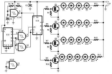
17 LEDs in four groups bar-mode sequence Suitable for shop-windows animation etc.
Published:2012/11/9 0:27:00 Author:muriel | Keyword: 17 LEDs, four groups , bar-mode sequence
View full Circuit Diagram | Comments | Reading(2207)
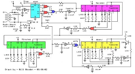
Binary Coded Decimal (BCD) Clocks
Published:2012/11/9 0:26:00 Author:muriel | Keyword: Binary Coded Decimal (BCD) , Clocks
View full Circuit Diagram | Comments | Reading(1185)
7-Segment LED Counter
Published:2012/11/9 0:22:00 Author:muriel | Keyword: 7-Segment, LED Counter
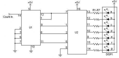
This simple counter can be used to count pulses, as the basis for a customer counter (like you see at the doors of some stores), or for anything else that may be counted. The circuit accepts any TTL compatible logic signal, and can be expanded easily (see Notes). (View)
View full Circuit Diagram | Comments | Reading(122)
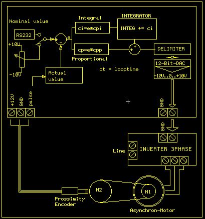
PID Motor control
Published:2012/11/9 0:21:00 Author:muriel | Keyword: PID Motor control
View full Circuit Diagram | Comments | Reading(1065)
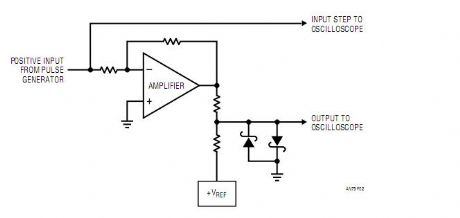
30 Nanosecond Settling Time Measurement for a Precision Wideband Amplifier
Published:2012/11/9 0:21:00 Author:muriel | Keyword: 30 Nanosecond, Settling Time, Precision Wideband Amplifier
View full Circuit Diagram | Comments | Reading(1073)
24 Second Shot Clock
Published:2012/11/9 0:19:00 Author:muriel | Keyword: 24 Second , Shot Clock
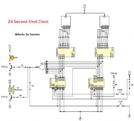
This is a circuit intended to be used in basketball shot clock.Notes:To start in 24 seconds; 24s LOAD SW and Reset SW should be push simultaneously. If not, the count will start in 99. Pulse input can be connected to 555 astable multivibrator but must be calibrated for real time clock. The PAUSE SW must have a Switch Debouncer so that the counter will count normal when counting is paused and then turn-on.When the count reach 00, the NOR gate will have an output of logic1 that will turn on the two transistor. The buzzer will rung and light will turn on. The two transistors are continuously turn-on not until LOAD SW and Reset SW is push. All have a +5v power supply. (View)
View full Circuit Diagram | Comments | Reading(1860)
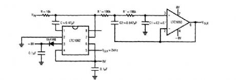
A 1mV Offset, Clock-Tunable, Monolithic 5-Pole Lowpass Filter
Published:2012/11/9 0:18:00 Author:muriel | Keyword: 1mV Offset, Clock-Tunable, Monolithic, 5-Pole Lowpass Filter
View full Circuit Diagram | Comments | Reading(609)
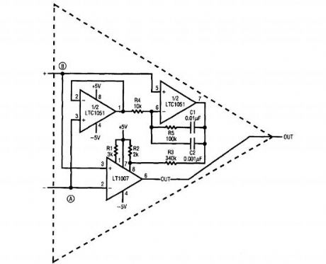
Ultra low noise op amp
Published:2012/11/9 0:16:00 Author:muriel | Keyword: Ultra, low noise, op amp
View full Circuit Diagram | Comments | Reading(1113)
LTC1050 chopper op amp
Published:2012/11/9 0:15:00 Author:muriel | Keyword: LTC1050 , chopper op amp
View full Circuit Diagram | Comments | Reading(1774)
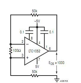
Recommended Drift Test Circuit
Published:2012/11/9 0:14:00 Author:muriel | Keyword: Recommended, Drift Test Circuit
View full Circuit Diagram | Comments | Reading(960)
Typical Thermal Layout Considerations
Published:2012/11/9 0:13:00 Author:muriel | Keyword: Thermal Layout

View full Circuit Diagram | Comments | Reading(746)
| Pages:280/2234 At 20261262263264265266267268269270271272273274275276277278279280Under 20 |
Circuit Categories
power supply circuit
Amplifier Circuit
Basic Circuit
LED and Light Circuit
Sensor Circuit
Signal Processing
Electrical Equipment Circuit
Control Circuit
Remote Control Circuit
A/D-D/A Converter Circuit
Audio Circuit
Measuring and Test Circuit
Communication Circuit
Computer-Related Circuit
555 Circuit
Automotive Circuit
Repairing Circuit