
Circuit Diagram
Index 263
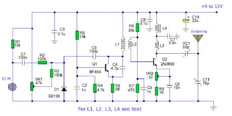
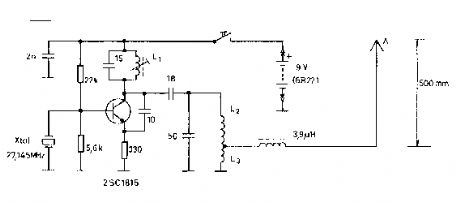
Long Range FM Transmitter circuits
Published:2012/11/23 0:58:00 Author:muriel | Keyword: Long Range, FM Transmitter circuits
View full Circuit Diagram | Comments | Reading(1243)
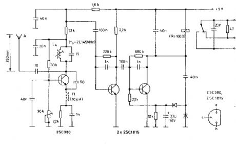
Band pass Filter and RF Preamp
Published:2012/11/23 0:55:00 Author:muriel | Keyword: Band pass Filter, RF Preamp
View full Circuit Diagram | Comments | Reading(1437)
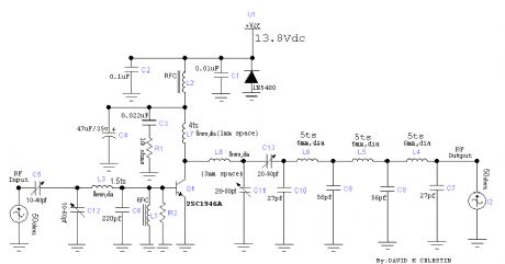
40 Meter Popcorn Superhet Receiver
Published:2012/11/23 0:54:00 Author:muriel | Keyword: 40 Meter, Popcorn Superhet, Receiver
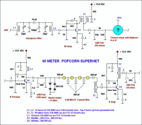
To the right is the schematic for a no-frills, relatively low-cost CW superhet receiver with a 4.00 MHz Intermediate frequency. There is no AGC or RF gain control, however this receiver has good large signal handling capability. This receiver uses just 6 bipolar transistors and an op amp for reasonable volume into headphones. Much of the ideas/design of the various stages must be credited to Wes Hayward as I borrowed heavily from his previous work and through ideas obtained by discussion. If one were to homebrew the diode ring mixers, indeed this would be a very low cost receiver giving reasonable performance which outperforms any NE602 based superhet receivers that I have built or listened to. Below the main schematic is a diplexer diagram that allows the builder to choose from one of two RF and AF diplexers used to terminate the diode ring mixers. (View)
View full Circuit Diagram | Comments | Reading(2159)
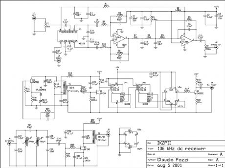
136 kHz direct conversion receiver
Published:2012/11/23 0:54:00 Author:muriel | Keyword: 136 kHz, direct conversion, receiver
1. Introduction
I describe a simple direct conversion receiver, thinked for QRSS and DFCW communications, as companion of ARGO or SPECTRAN programs. I don't pretend to beat the performances of professional or commercial ham radio receiver, the scope is to suggest an easy way for beginner to listen (of course I mean look at) the signals in this poorly populated band. The receiver is useful also as portable receiver, fast turn-on receiver for a quick look an the band or as very low cost (and performances) spectrum analyzer. I currently use this equipment for tests purposes (e.g. visual frequency meter etc.).
2. Circuit description
The front end is described elsewhere prea136.htm The scope is reduce as most as possible the image frequency. I have also tried a different front end, based on a low pass filter with frequency cut-off of 180 kHz. In my QTH I had a lot of undesirables signals on the screen of the PC. The filter is tuned with a signal generator for a bandwidth of 300 Hz, centered on 136.650 kHz. The coupling capacitor between the coils is also tuned for the desired bandwidth. The mixer is the well known NE602. It's not a monster of performances but it provides some gain, it's cheap and easy to find. The rest of audio amplifier is common to other direct conversion receiver. The local oscillator is the original part of my project. The frequency is fixed at 135.500 kHz, so that the image frequency for QRSS portion of the band (137.600 - 137.800 kHz)drop about 4 kHz lower. This permitted to attenuate the image using a simple front end filter. The oscillator is controlled by a 27.100 MHz crystal, the frequency is divided by 200 and the square wave is injected into the mixer. Adjust the trimmer V1 for the best signal to noise ratio (or the best sensitivity). CV1 is tuned for a secure start of oscillations, tune CV2 for the exact frequency of 27.100 MHz. The transformer T1 is winded on an Amidon T50-5 toroidal core. 19 turn primary, 4 turn secondary. There is not an audio amplifier, the output must be connected to the audio board of the computer. If you prefer an audio feedback use an IC amplifier (e.g. an LM386). I usually set-up ARGO offset frequency to read the actual frequency on the screen of the PC. I suggest to use a low noise operational amplifier as U2.
3. Performances
The stability is good since the drifts of the xtal oscillator are divided by 200. The sensitivity is also good since the natural and artificial noise on the band is high. The high selectivity filter in the front end reduce the possibility of overloading of the mixer. In my station the receiver is connected to the antenna through the low pass filter of the transmitter, helping in reducing overload from broadcasting stations. I think that a tuned loop antenna is the optimal companion for this receiver. (View)
View full Circuit Diagram | Comments | Reading(1800)
RC model receivers
Published:2012/11/23 0:53:00 Author:muriel | Keyword: RC model, receivers
View full Circuit Diagram | Comments | Reading(899)
toy car receiver
Published:2012/11/23 0:52:00 Author:muriel | Keyword: toy car , receiver
View full Circuit Diagram | Comments | Reading(1527)
superregenerative receiver
Published:2012/11/23 0:52:00 Author:muriel | Keyword: superregenerative receiver
View full Circuit Diagram | Comments | Reading(1276)
Superregenerative radio receiver
Published:2012/11/23 0:50:00 Author:muriel | Keyword: Superregenerative, radio receiver
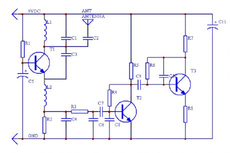
This is a simple RF receiver mainly for low-distance digital radio receiver application. The analog output of this circuit should be connected to a schmitt-trigger signal conditioning circuit with a proper value capacitor (from collector of T3). L1 for 27Mhz is about 10 turns, 6 mm diameter coil body. The circuit is suitable for other frequencies if L1 is changed. (View)
View full Circuit Diagram | Comments | Reading(2816)
Antenna Tuning Unit
Published:2012/11/23 0:48:00 Author:muriel | Keyword: Antenna Tuning Unit
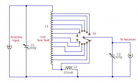
A simple passive (no power required) circuit to match an antenna to a radio receiver. This will be a useful addition to the short wave listener, but in addition a medium wave coil is almost used to tune the medium wave band. (View)
View full Circuit Diagram | Comments | Reading(1483)
30 Watt VHF Amplifier
Published:2012/11/23 0:47:00 Author:muriel | Keyword: 30 Watt, VHF Amplifier
View full Circuit Diagram | Comments | Reading(965)
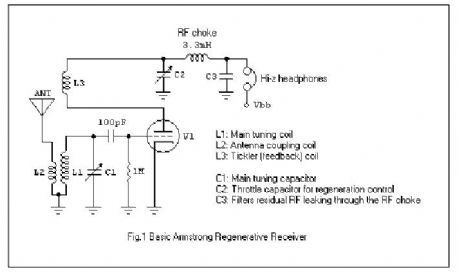
The Modern Armstrong Regenerative Receiver
Published:2012/11/23 0:47:00 Author:muriel | Keyword: Modern , Armstrong , Regenerative Receiver
View full Circuit Diagram | Comments | Reading(1863)
TV Transmitter circuits
Published:2012/11/23 0:46:00 Author:muriel | Keyword: TV Transmitter circuits
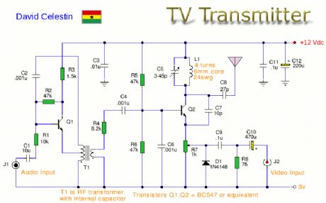
This is an Analogue TV Transmitter. Sound modulation is type FM with a 5.5MHz carrier and video transmission is PAL. Frequency is adjustable via C5 and tunes 54 to 216Mhz with components shown. This is suitable for countries using TV systems B and G. (View)
View full Circuit Diagram | Comments | Reading(2558)
MK484 Radio with Loudspeaker
Published:2012/11/23 0:45:00 Author:muriel | Keyword: MK484, Radio, Loudspeaker
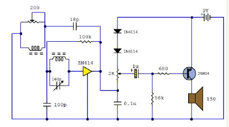
A complete AM radio set based on the MK484 IC (formerly ZN414). It uses a PNP transistor and can drive a 150R loudspeaker. (View)
View full Circuit Diagram | Comments | Reading(1953)
Automatic Repeater
Published:2012/11/23 0:44:00 Author:muriel | Keyword: Automatic Repeater
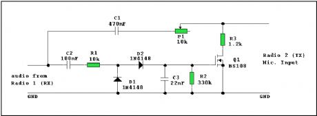
This circuit will be of interest to the radio amateur and anyone posessing two radios, (one of which must be able to transmit i.e. a transceiver). It is a self powered (audio derived) repeater circuit for receiving a signal and re-transmitting it via the other radio. (View)
View full Circuit Diagram | Comments | Reading(1731)
FM Transmitter circuits
Published:2012/11/23 0:43:00 Author:muriel | Keyword: FM Transmitter circuits
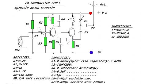
A portable FM transmitter that can be used to replace a FM microphone. (View)
View full Circuit Diagram | Comments | Reading(1051)
SW Regenerative Receiver
Published:2012/11/23 0:42:00 Author:muriel | Keyword: SW Regenerative, Receiver
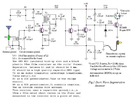
Sensitivity and selectivity are issues that will invariably concern a short wave listener when he wishes to purchase a new receiver. Commercially available communications equipment will undoubtedly fulfill his expectations, but we are talking here of highly priced products. Low-cost alternatives call mainly for homebrewed radios, and in this sense, the regenerative receiver is the common choice due to its simplicity, low parts count and very acceptable performance.
The author is also a short wave enthusiast and for some time used his family's Philips MW/SW vacuum tube radio. Later, he changed to a solid-state Sony ICF-7600, a high selectivity receiver featuring ceramic filters in the IF stages. Then he would discover how much fun he could have building radios on his spare time. After testing a variety of schematics available in books and on the web, the author finally decided to make his own designs.
Back in 2003, an experimental Colpitts-type shortwave regenerative receiver was made public on the web by this servant. It was reported to tune from the 22-meter band up to the 11-meter band with a single set of coils. Operation was found to be satisfactory with the prototype built on a protoboard and a ground plane fixed underneath. Further work with the receiver using different sets of coils revealed a larger usable frequency spectrum.
Fig.1 shows the schematic diagram of an improved version of the early receiver. It will tune signals from 3500kHz up to 26MHz, roughly in three bands, each with a 1.96:1 frequency-ratio. It must be quoted that the said frequency ratio is what the author got for his prototype. It is a function of the maximum-to-minimum capacitance of the variable tuning capacitor and the stray capacitance of the circuit layout. (View)
View full Circuit Diagram | Comments | Reading(3173)
LF Crystal Controlled Oscillator
Published:2012/11/23 0:42:00 Author:muriel | Keyword: LF Crystal, Controlled Oscillator
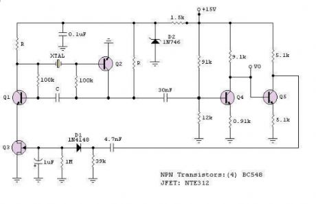
The RF engineer sometimes has to look for an instrument that will check a low frequency quartz crystal unit reliably and rapidly. This is a difficult piece of equipment to find and the engineer often has to consult an electronic circuits handbook for the schematic of a circuit that will perform the task.Unfortunately, there aren't many such circuits in the technical literature currently available, and when found, they don't always work as expected. A circuit that has been found to work at full satisfaction in the frequency range from 10 kHz to 500 kHz is illustrated in Figure 1. (View)
View full Circuit Diagram | Comments | Reading(805)
A Bipolar Regenerative Receiver
Published:2012/11/23 0:40:00 Author:muriel | Keyword: Bipolar, Regenerative Receiver
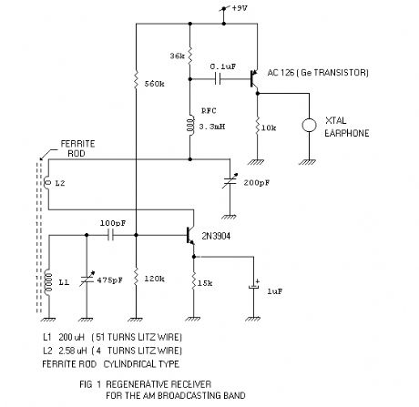
Contrary to what some radio experimenters think, a bipolar regenerative design can be made to work efficiently. The major concern is the low input impedance of the detector-amplifier bipolar stage. Nevertheless, it can be easily compensated with positive feedback or regeneration. A sufficient amount of regeneration can make tuning astonishingly sharp. Another concern is the quality of the detected audio. This, to my knowledge, is subjective. The quality of sound coming out from an earphone can be rated good or fair by two different people. I would suggest that you decide by yourself. So, come on and try the following schematic for the 530 kHz to 1650 kHz AM Broadcasting Band. (View)
View full Circuit Diagram | Comments | Reading(934)
Band 2 Preamplifier
Published:2012/11/23 0:39:00 Author:muriel | Keyword: Band 2, Preamplifier
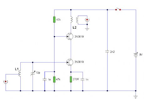
This is a VHF amplifier for the Band 2 Radio Spectrum tuning approximately 88 - 108 Mhz. (View)
View full Circuit Diagram | Comments | Reading(823)
SW Aerial Amplifier
Published:2012/11/23 0:38:00 Author:muriel | Keyword: SW Aerial, Amplifier

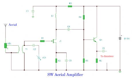
A radio frequency amplifier to boost SW reception. Frequency range approximately 5 to 20 MHz. (View)
View full Circuit Diagram | Comments | Reading(1052)
| Pages:263/2234 At 20261262263264265266267268269270271272273274275276277278279280Under 20 |
Circuit Categories
power supply circuit
Amplifier Circuit
Basic Circuit
LED and Light Circuit
Sensor Circuit
Signal Processing
Electrical Equipment Circuit
Control Circuit
Remote Control Circuit
A/D-D/A Converter Circuit
Audio Circuit
Measuring and Test Circuit
Communication Circuit
Computer-Related Circuit
555 Circuit
Automotive Circuit
Repairing Circuit