
Circuit Diagram
Index 274
Mini FM Radio Transmitter
Published:2012/11/15 0:27:00 Author:muriel | Keyword: Mini, FM, Radio, Transmitter
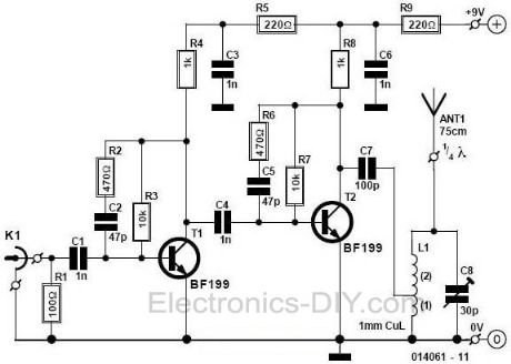
This small FM transmitter with a range of about 50 meters designed for hoby. With lots of mini-transmitters then you have a comprehensive, action-packed radio program. Due to the power supply via the USB port of a high frequency stability is achieved. Alternatively, the receiver, a battery 5 to 12 volts to operate.
Mini FM Radio Transmitter circuit with BF199. Tags: BF199, Mini fm radio Transmitter circuit, radio transmitter circuit, rc transmitter circuit, receiver circuit, rf transmitter circuit, small FM transmitter, transducer circuit, transistor circuit, video transmitter circuit, wireless transmitter circuit (View)
View full Circuit Diagram | Comments | Reading(1952)
Micro Spy PLL FM Transmitter
Published:2012/11/15 0:26:00 Author:muriel | Keyword: Micro, Spy, PLL , FM, Transmitter
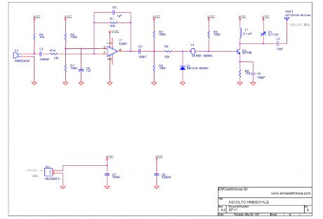
This micro spy PLL FM Transmitter transmits on the 160MHz frequency (if we use a 40MHz quartz) and therefore can be listened through a receiver tuned on this frequency. This circuit can be used to on various frequencies, for example on the FM band 88-108 just modifying some components, among which the quartz (25MHz). Voice is detected by an electret microphone, then it is amplified and filtered by U1 pass-band in order then to be modulated from the carrier section, where through the varicap diode it mixes with the frequency generated by the quartz, that guarantees an adapted stability. Practically the modulating voltage is obtained applying the audio signal to the resonating circuit varicap diode that determines the carrier oscillation. The carrier frequency (160 MHz) must be greater than the modulating frequency (300-3300 Hz) audio band. The transmission is on the fourth harmonic, therefore 160MHz, the oscillation frequency of the driver RF transistor Q1. A small calibration is allowed acting on the L1 inductance and the C1 Trimmer Capacitor. (View)
View full Circuit Diagram | Comments | Reading(1995)
LowPass Filter
Published:2012/11/15 0:23:00 Author:muriel | Keyword: LowPass Filter
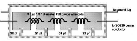
The schematic you find here comes from another site on the internet, but because it's on so many sites, we don't know who actually designed it. However it's a nice one. Capacitors: C1,C4 22pF cer. C2,C3 51pF cer. Coils: L1,L2,L3 #18 bus wire, 1/4 diameter, 3 turns * Form the leads from the capacitors as shown in the little figure below. Then solder them from the pad to the outside ground area. * Be sure that the turns from the coil are seperated by the same distance as the diameter of the wire * Form the leads from the coils as shown in the little figure below. Then solder them in place. * Place the filter in a metal box, with rf-connectors on both ends ( SO239(=PL259), BNC or N-connectors) (View)
View full Circuit Diagram | Comments | Reading(1879)
Low Pass Filter For FM 88-108 MHz
Published:2012/11/15 0:22:00 Author:muriel | Keyword: Low Pass , Filter, FM , 88-108 MHz
View full Circuit Diagram | Comments | Reading(2757)
Long Range FM Transmitter Circuit
Published:2012/11/15 0:21:00 Author:muriel | Keyword: Long Range , FM , Transmitter Circuit
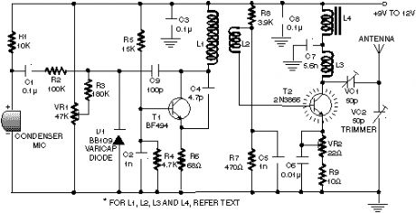
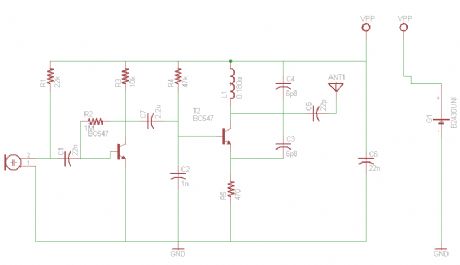
This circuit is a circuit diagram fm transmitter. This circuit is somewhat different from the previous fm transmitter circuit. Transmitter circuit described here has the additional RF power amplifier stage, after the oscillator stage, to increase the power output of 200-250 milliwatts. With a good matching 50-ohm ground plane antenna or multi-element yagi antenna, this transmitter can provide a good enough signal strength to a distance of about 2 kilometers.
The circuit built around transistor T1 (BF494) is the basic low-power variable-frequency VHF oscillator. A varicap diode circuit is included to change the frequency of the transmitter and to provide frequency modulation by audio signals. The output of the oscillator is about 50 milliwatts. Transistor T2 (2N3866) forms a VHF-class power amplifier. This increases the oscillator signals� power four to five times. Thus, 200-250 milliwatts of power produced at the collector of transistor T2. For better results, assemble the circuit on a good quality glass epoxy board and house the transmitter in the case of aluminum. Shield the oscillator stage using aluminum sheets. Transistor T2 must be mounted on the heat sink. Do not switch on the transmitter without a matching antenna. Adjust both trimmers (VC1 and VC2) for maximum transmission power. Adjust potentiometer VR1 to set the fundamental frequency near 100 MHz. Coil winding details are given below: L1 � 4 changes of 20 SWG wire close wound over 8mm diameter plastic former. L2 � 2 changes of 24 SWG wire near top end of L1. (Note: There is no core (ie air core) is used to coil on top) L3 � 7 changed from 24 SWG wire close wound with 4mm diameter air core. L4 � 7 changed from 24 SWG wire-wound on ferrite beads (choking) Potentiometer VR1 is used to change the fundamental frequency whereas potentiometer VR2 is used as power control. (View)
View full Circuit Diagram | Comments | Reading(1186)
Long Range FM Transmitter-2
Published:2012/11/15 0:21:00 Author:muriel | Keyword: Long Range, FM , Transmitter
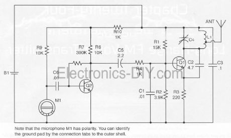
Part List: R1_______15K R2_______3K9 R3_______220R R4,R5____1K R6,R9____10K R7_______390K C1,C6____0.01uF C2_______4.7pF C3_______0.1uF C4_______6-35pf trimmer cap C5_______2.2uF B1_______3V L1_______Coil winding (see below) Q1,Q2____PN2222 M1_______Special FET bypassed microphone Assemble L1 : Form L1 by tightly wrapping eight turns of #16 bus wire on a #8 wood screw. Produces an eight-turn coil with an inner diameter of approximately 0.135 inches and lenght of about 0.625 inches. Insert in the proper hole and solder as shown.
(View)
View full Circuit Diagram | Comments | Reading(1273)
Long Range FM Transmitter
Published:2012/11/15 0:19:00 Author:muriel | Keyword: Long Range, FM , Transmitter
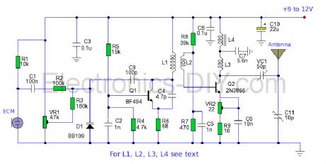
The power output of many transmitter circuits are very low because no power amplifier stages are incorporated. The transmitter circuit described here has an extra RF power amplifier stage, after the oscillator stage, to raise the power output to 200-250 milliwatts. With a good matching 50-ohm ground plane antenna or multi-element Yagi antenna, this transmitter can provide reasonably good signal strength up to a distance of about 2 kilometres. The circuit built around transistor T1 (BF494) is a basic low-power variable-frequency VHF oscillator. A varicap diode circuit is included to change the frequency of the transmitter and to provide frequency modulation by audio signals. The output of the oscillator is about 50 milliwatts. Transistor T2 (2N3866) forms a VHF-class A power amplifier. It boosts the oscillator signal power four to five times. Thus, 200-250 milliwatts of power is generated at the collector of transistor T2.
For better results, assemble the circuit on a good-quality glass epoxy board and house the transmitter inside an aluminum case. Shield the oscillator stage using an aluminum sheet. Coil winding details are given below: L1 - 4 turns of 20 SWG wire close wound over 8mm diameter plastic former. L2 - 2 turns of 24 SWG wire near top end of L1. (Note: No core (i.e. air core) is used for the above coils) L3 - 7 turns of 24 SWG wire close wound with 4mm diameter air core. L4 - 7 turns of 24 SWG wire-wound on a ferrite bead (as choke) Potentiometer VR1 is used to vary the fundamental frequency whereas potentiometer VR2 is used as power control. For hum-free operation, operate the transmitter on a 12V rechargeable battery pack of 10 x 1.2-volt Ni-Cd cells. Transistor T2 must be mounted on a heat sink. Do not switch on the transmitter without a matching antenna. Adjust both trimmers (VC1 and VC2) for maximum transmission power. Adjust potentiometer VR1 to set the fundamental frequency near 100 MHz. This transmitter should only be used for educational purposes. Regular transmission using such a transmitter without a license is illegal in India.
(View)
View full Circuit Diagram | Comments | Reading(1695)
The neutral point voltage open phase voltage relay protection circuit
Published:2012/11/14 19:52:00 Author:Ecco | Keyword: neutral point, voltage, open phase, voltage relay, protection
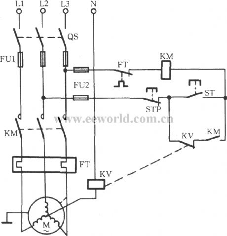
When any one phase of the motor three-phase power supply loses power, if the motor uses Y connection, wherein the neutral point (midpoint) voltage will be significantly improved. Therefore, the midpoint voltage can be used as off -phase fault signal. As shown in figure, the circuit uses voltage relay for protection device.
(View)
View full Circuit Diagram | Comments | Reading(1923)
Resistance-capacitance phase protection circuit
Published:2012/11/14 19:34:00 Author:Ecco | Keyword: Resistance-capacitance , phase protection
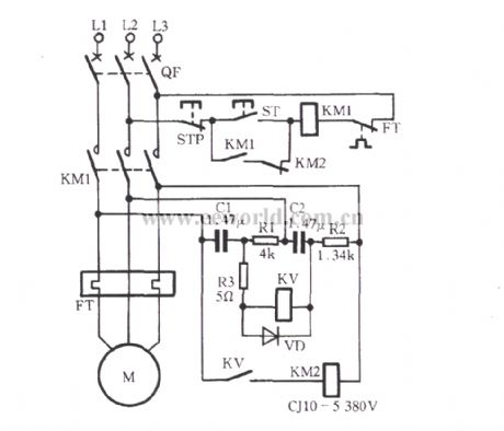
The circuit shown in Figure uses negative sequence voltage generated by unbalanced three-phase power for phase-failure protection. When the three-phase power is symmetric and line voltage has mutual lag 120°electrical angle, the voltage across the relay KV voltage is 0V, so KV has no action. When the three-phase power loses a phase, the voltage is applied to the ends of the coil, KV pulls in, and its normally open contact action to turn on KM2 coil loop, then the normally closed contact KM2 action, KM1 cuts the power supply of motor M.
(View)
View full Circuit Diagram | Comments | Reading(3104)
DA6340 VCR infrared remote control receiver preamplifier circuit
Published:2012/11/14 20:03:00 Author:Ecco | Keyword: VCR, infrared, remote control , receiver, preamplifier
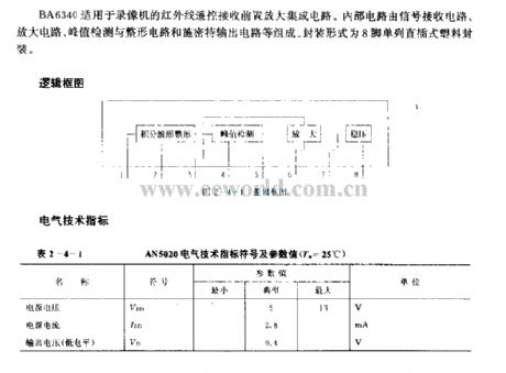
BA6340 is suitable for the VCR 's infrared remote control receiver preamplifier integrated circuit. Internal circuit consists of the signal receiving circuit, amplifier circuit, peak detector, shaping circuit and the Schmitt output circuit, etc. It uses 8-pin single in-line plastic package.
(View)
View full Circuit Diagram | Comments | Reading(1165)
555 automatically pushed coal timing control circuit
Published:2012/11/14 20:07:00 Author:Ecco | Keyword: 555, automatically pushed coal , timing control
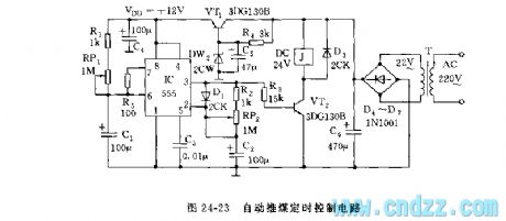
As shown in Figure 24-23, the control circuit is composed of adjustable buck power and multivibrator with adjustable duty cycle and VT2 relay control circuit. R1, RP1 and C1 form charging circuit.
(View)
View full Circuit Diagram | Comments | Reading(935)
△ connection motor phase failure voltage relay protection circuit
Published:2012/11/14 20:18:00 Author:Ecco | Keyword: △ connection, motor , phase failure, voltage relay protection
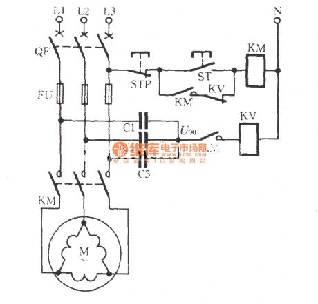
For △ connection motor, you must add neutral point, that is, three Y-shaped capacitors are connected ( impedance element ) with the motor in parallel, then the neutral point of Y shape is connected to the relay protection element, and it is shown in figure. During normal operation of the motor phase power supply, the neutral point voltage U00 is typically less than 10V.
(View)
View full Circuit Diagram | Comments | Reading(1933)
iPod FM Transmitter
Published:2012/11/14 0:57:00 Author:muriel | Keyword: iPod , FM Transmitter
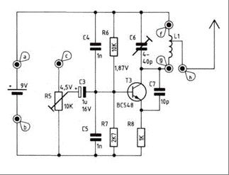
Here are instructions for building your own ipod FM radio transmitter. It works quite easy, there is a power switch on the bottom to turn it on and tune your radio and transmitter to the right frequency. For the antenna you can use a copper wire of 70 cm. The range of this FM transmitter is about 100 to 150 meters (500 feet). With R5 you can adjust the input signal and with C6 you can tune your frequency. Transmitter is supplied by 9V battery.
iPod FM Transmitter parts list: Transistor: T3 ...............................2N2219a Capacitor: C3 ...............................1 μF/16 V C4,C5 .........................1 nF ker. C6 trimmer capacitor...4-40 pF C7 ...............................10 pF ker. Resistor: R5 Trimmer.................10 kΩ R6 .............................. 10 kΩ R7 ...............................2,7 kΩ R8................................1 kΩ Spool L1: Use a 10 cm long Silver wire. The diameter inside the spool should be 3 mm. 7 winds total Length of the spool should be 15 mm (f-g) The antenna is connected to the spool at 3mm from f a: + 9volt b: ground c: audio in Ground your audio input to b For the antenna you can use a copper wire (70 cm) With R5 you can adjust the input signal and with C6 you can tune your frequency.
(View)
View full Circuit Diagram | Comments | Reading(2583)
High Power FM Wireless Microphone
Published:2012/11/14 0:55:00 Author:muriel | Keyword: High Power , FM , Wireless, Microphone
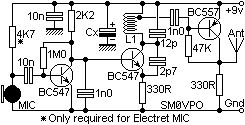
This FM Wireless Microphone has been a very popular project with beginners and experienced constructors alike. It has been used inside guitars and as the basis of a remote control system. I do however, receive many requests for a higher powered circuit and better microphone sensitivity. This High Power FM Wireless Microphone has a better frequency stability, over 1 Km range and is good on microphone sensitivity. This has been achieved by adding an RF amplifier buffer (with 10dB gain) and an AF preamplifier to boost the modulation a little.
Construction is quite simple. L1 is 3.25 turns in spiral form and is an integral part of the PCB foil pattern. The two BC547 transistors can be replaced with (almost) any small-signal NPN transistor, such as the 2N2222. The final stage is a BC557 PNP general purpose device. If you use different devices then you should select the 1M0 resistor for 5-volts DC at the collector of the the first transistor. Select the 47K resistor for 3 � 4 volts on the collector of the third transistor. Here is the V5 component overlay drawing. Note that there is a modification: The PCB is 50mm x 25mm, a little larger than the first version but there are three stages instead of just the one. The first prototype is shown above, beside the battery powering it. The output power is about +10dBm which is about 10dB more than the first FM Wireless Microphone. This would theoretically give it 3.12 times the range (1.6Km) but I have only tested it using a handheld with the TX laying on the bench indoors. But I got a comfortable 700 meters (and a few funny looks from our neighbours). Above you can see the addition of a capacitor added across the 12p tuning capacitor to lower the frequency of the transmitter. Make the capacitor by twisting two lengths of single core insulated hook-up wire, about 2cm long. This will reduce the frequency to the bottom end of the band. Cut short the capacitor to increase the frequency to the desired final frequency. If you cut it a few KHz too high then just twist the gimmick a little tighter. (View)
View full Circuit Diagram | Comments | Reading(1869)
FM Transmitter with Varactor Diode Tuning
Published:2012/11/14 0:54:00 Author:muriel | Keyword: FM Transmitter , Varactor Diode Tuning
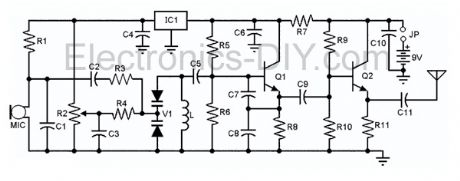
Presented here is a low-power FM transmitter with varactor diode tuning using surface-mount devices (SMD) that will be received with a standard FM radio. Soldering surface mounted devices is not so hard and actually is quite easy. There are many designs for small FM transmitters but they have some problems. First, you need an audio amplifier to get enough modulation. Second, the antenna is attached directly to the collector. Third, the coil L must be wound by hand and adjusted by stretching. It all ads with a weak signal that tends to drift in frequency. In contrast the transmitter schematic we present here eliminates some of those problems, using varactor diode for tuning and modulation, givin great sensitivity without an audio amplifier. (View)
View full Circuit Diagram | Comments | Reading(2052)
FM Transmitter with 2N2218
Published:2012/11/14 0:54:00 Author:muriel | Keyword: FM Transmitter, 2N2218
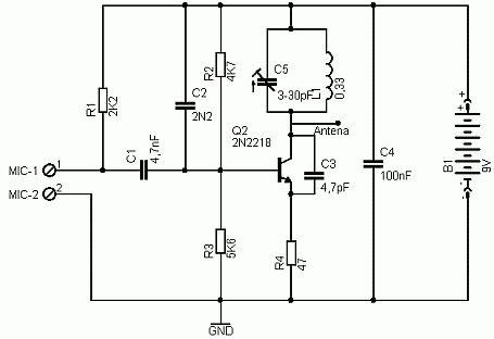
Here's simple FM transmitter circuit using medium power 2N2218 transistor. Micropohone is of electret type that connects to two input terminals and the antenna should be a copper wire from 15 to 40 cm. Below is schematic circuit of the fm transmitter. (View)
View full Circuit Diagram | Comments | Reading(2748)
FM Transmitter Circuit
Published:2012/11/14 0:53:00 Author:muriel | Keyword: FM , Transmitter Circuit
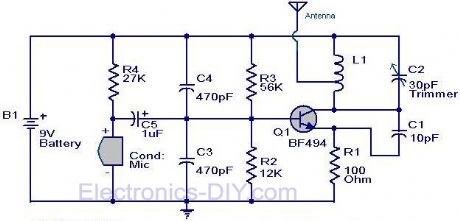
Here is the circuit diagram of the simple FM transmitter using a transistor. Great performance or range is not guaranteed here, because this is an elementary design. General purpose radio frequency transistor BF 494 (Q1) is used here for obtaining FM modulation. A condenser mic is used here to pickup the sound.The condenser mic converts the sound to electrical variations and this variations are fed to the base of Q1 , which performs the amplification as well as modulation.The capacitor C2 and L1 determines the frequency of transmission.The circuit can be powered from a 9V transistor radio battery.
Notes The coil L1 can be made by winding 8 turns of 1mm thick enamel coated copper wire on a ball pen refill. The coil should be tapped at the center for connecting the antenna. A 30 cm wire can be used as an antenna. Remember! This circuit is an elementary circuit.No good performance or range is not guaranteed.Ideal for demo applications only.I got only 8 meter range with some decent sound quality. Battery is strictly recommended because mains powered supply may induce additional noise. (View)
View full Circuit Diagram | Comments | Reading(1286)
FM Transmitter Bug
Published:2012/11/14 0:52:00 Author:muriel | Keyword: FM , Transmitter Bug
The goal of this project is for me personally to learn a little more about fm transmitters and fm bug making (may the HAM radio gods bless me in this pursuit). The ideal outcome of this project is a very small and full functional FM transmitter that we can stick into a plastic mint box. In order to be able to build this, we'll have to learn a lot about amplifiers, LC oscillators, mixers, antennas and FM. This project assumes you're already comfortable build your own PCB boards. If you're not please take a look at the homemade pcb's tutorial before you continue. It will help you out a lot.
So we've already seen mint can MP3 players and mint can amplifiers for guitars and tons of other projects, why not an FM bug transmitter? Well for starters, a tin can would be the worst place to put an fm transmitter! Luckily I stumbled upon this plastic mint box and thought...why not? Two transistor FM transmitters and FM bug circuits are all over the internet and they all share a common design that will be followed in this project as well. The reason I'm not trying to invent something new here is simply because FM transmitters have been redesigned to death. Why not instead have some fun with it? (View)
View full Circuit Diagram | Comments | Reading(909)
FM Telephone Transmitter
Published:2012/11/14 0:51:00 Author:muriel | Keyword: FM, Telephone , Transmitter
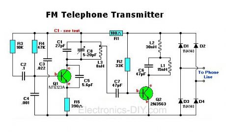
The FM telephone circuit is built on a PC board that is so small it can easily be fitted inside the housing of a telephone making it an instant pseudo-speak earphone. This FM transmitter circuit connects in series with telephone line, steals power from it, and transmits both sides of the conversation to an FM radio tuned between 90 and 95 MHz. (View)
View full Circuit Diagram | Comments | Reading(1891)
FM Broadcast Transmitter
Published:2012/11/14 0:50:00 Author:muriel | Keyword: FM, Broadcast, Transmitter
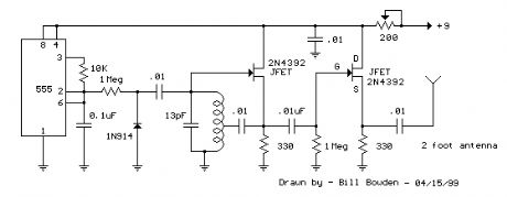
This FM Broadcast Transmitter circuit will transmit a continuous audio tone on the FM broadcast band (88-108 MHz) which could used for remote control or security purposes. Circuit draws about 30 mA from a 6-9 volt battery and can be received to about 100 yards. A 555 timer is used to produce the tone (about 600 Hz) which frequency modulates a Hartley oscillator. A second JFET transistor buffer stage is used to isolate the oscillator from the antenna so that the antenna position and length has less effect on the frequency. Fine frequency adjustment can be made by adjusting the 200 ohm resistor in series with the battery. Oscillator frequency is set by a 5 turn tapped inductor and 13 pF capacitor.
The inductor was wound around a #8 X 32 bolt (about 3/16 diameter) and then removed by unscrewing the bolt. The inductor was then streached to about a 3/8 inch length and tapped near the center. The oscillator frequency should come out somewhere near the center of the band (98 MHz) and can be shifted higher or lower by slightly expanding or compressing the inductor. A small signal diode (1N914 or 1N4148) is used as a varactor diode so that the total capacity in parallel with the inductor varies slightly at the audio rate thus causing the oscillator frequency to change at the audio rate (600 Hz). The ramping waveform at pins 2 and 6 of the timer is applied to the reversed biased diode through a large (1 Meg) resistor so that the capacitance of the diode changes as the ramping voltage changes thus altering the frequency of the tank circuit. Alternately, an audio signal could be applied to the 1 Meg resistor to modulate the oscillator but it may require an additional pullup resistor to reverse bias the diode. The N channel JFET transistors used should be high frequency VHF or UHF types (Radio Shack #276-2062 MPF102) or similar.
(View)
View full Circuit Diagram | Comments | Reading(936)
| Pages:274/2234 At 20261262263264265266267268269270271272273274275276277278279280Under 20 |
Circuit Categories
power supply circuit
Amplifier Circuit
Basic Circuit
LED and Light Circuit
Sensor Circuit
Signal Processing
Electrical Equipment Circuit
Control Circuit
Remote Control Circuit
A/D-D/A Converter Circuit
Audio Circuit
Measuring and Test Circuit
Communication Circuit
Computer-Related Circuit
555 Circuit
Automotive Circuit
Repairing Circuit