
Circuit Diagram
Index 279
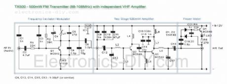
TX-500 - 500mW FM transmitter
Published:2012/11/9 20:46:00 Author:muriel | Keyword: TX-500 , 500mW, FM, transmitter
View full Circuit Diagram | Comments | Reading(1447)
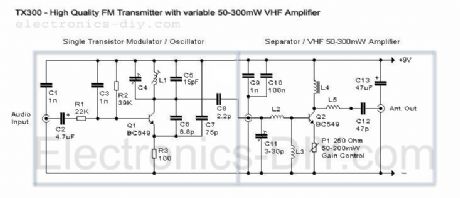
TX-300 - 50-300mW FM Transmitter
Published:2012/11/9 20:45:00 Author:muriel | Keyword: TX-300, 50-300mW , FM, Transmitter
View full Circuit Diagram | Comments | Reading(1051)
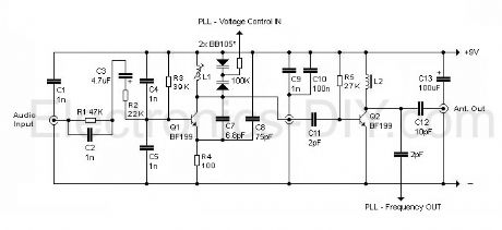
How to use PLL to digitally tune the frequency of the TX200 transmitter?
Published:2012/11/9 20:44:00 Author:muriel | Keyword: TX200 transmitter
View full Circuit Diagram | Comments | Reading(962)
TX200 Power Meter
Published:2012/11/9 20:44:00 Author:muriel | Keyword: TX200, Power Meter
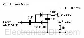
TX200 comes with built-in LED based power meter. This is a very helpful tool that will tell you if your transmitter's oscillator is working properly. If RF signal is transmitted the LED will illuminate. Besides that, it will also give you a quick visual way to check how much power is being transmitted. I highly recommend that you have the transmitter and power meter on the same PCB. If you like to experiment a lot, you will appreciate this inexpensive but externally helpful addition. (View)
View full Circuit Diagram | Comments | Reading(1793)
TX200 - high quality 200mW FM Transmitter
Published:2012/11/9 20:43:00 Author:muriel | Keyword: TX200 , high quality, 200mW, FM , Transmitter
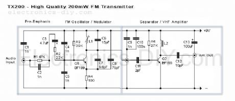
Here is the latest and greatly improved TX200 VFO/VCO FM transmitter. The most versatile transmitter to date that can be turned into high fidelity stereo PLL based 200mW FM transmitter. It is a perfect circuit for transmitting your music around the house and yard. TX200 uses only two coils; one in the oscillator and the other one in the 200mW VHF amplifier so it should be fairly easy for anyone to build. It also includes built-in pre-emphasis and C5 for enhanced sound quality. While assembling the transmitter care must be taken to make sure that C1 is directly connected to L1 and C9 to L2. These caps eliminate the distortions form the DC supply and improve the sound quality greatly. 9V voltage supply is also very important because it provides the exact amount of current to Q1 to produce loud and clear sound quality. I hope that you'll have as much fun as I had while building this transmitter. Enjoy! ;) (View)
View full Circuit Diagram | Comments | Reading(1334)
Single Chip FM Transmitter
Published:2012/11/9 20:42:00 Author:muriel | Keyword: Single Chip , FM , Transmitter
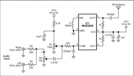
A simple FM transmitter links your home-entertainment system to a portable radio that can be carried around the house and into the back yard. For example, you can play music on the CD changer in your living room, and listen to it on a portable radio by the back-yard barbeque.
IC1 is a voltage-controlled oscillator with integrated varactor. Its nominal frequency of oscillation is set by inductor L1, and a 390nH value places that frequency at 100MHz. Potentiometer R1 then lets you select a channel by tuning over the FM band of 88MHz to 108MHz. Output power is about -21dBm into 50 (most countries accept emissions below 10dBm in the FM band).
The home system's left and right audio signals are summed by R3 and R4, and attenuated by the (optional) potentiometer R2. R2's wiper signal serves as a volume control by modulating the RF frequency. Signals above 60mV introduce distortion, so the pot attenuates down from that level.
In the absence of a standard FM radio antenna, 75cm (30 inches) of wire will suffice as a transmitting antenna. For best reception, it should be mounted parallel with the receiving antenna. The IC operates on a single supply voltage in the range 3V to 5V, but you should regulate the applied voltage to minimize frequency drift and noise. (View)
View full Circuit Diagram | Comments | Reading(1014)
Phone FM Transmitter
Published:2012/11/9 20:36:00 Author:muriel | Keyword: Phone, FM, Transmitter
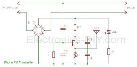
This Phone FM transmitter connects in series to your telephone line and transmits the telephone conversation over the FM band when you pick up the telephone handset. Transmitted signal can be tuned by any FM receiver. The circuit includes an On Air LED indicator and also provides a switch which can be used to turn off the transmitter. A unique feature of the circuit is that no battery is needed to operate the circuit since power is taken from the telephone line.
The transmitter uses only a short piece of wire aerial about 4 / 10 cm long to transmit the signal and some of the RF signal is also radiated through the telephone line itself. The circuit might be used to share or record conversations, but is not intended for illegal use.
(View)
View full Circuit Diagram | Comments | Reading(837)
500mW FM / VHF Transmitter Amplifier / Booster
Published:2012/11/9 20:34:00 Author:muriel | Keyword: 500mW , FM / VHF , Transmitter , Amplifier , Booster
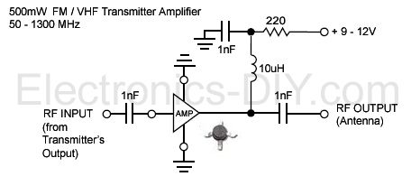
You can easily boost output power and range of BA1404 FM Transmitter by adding this simple high performance 500mW amplifier / booster. The amplifier chip is an integrated circuit containing multiple transistor stages and all other parts conveniently within a single small package. Boosting BA1404 FM transmitter's power has never been easier and the output signal can also directly drive 2N4427 or 2N3886 transistors for 1W or 5W of RF output power. (View)
View full Circuit Diagram | Comments | Reading(3723)
Optional 12V to 3V Voltage Regulator
Published:2012/11/9 20:34:00 Author:muriel | Keyword: Optional , 12V to 3V , Voltage Regulator
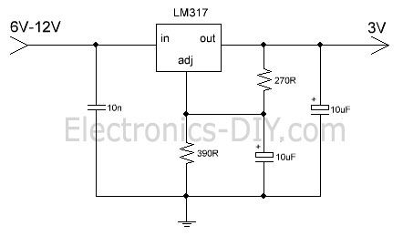
If you need to supply BA1404 FM Transmitter from 12V this simple circuit will do the job. It converts 12V voltage to 3V suitable for BA1404 chip using LM317 voltage regulator. 270 and 390 Ohm resistor determine the output voltage. (View)
View full Circuit Diagram | Comments | Reading(13239)
The directly driving capacitive input A / D converter circuit diagram with INA321/322
Published:2012/11/9 19:36:00 Author:Ecco | Keyword: directly driving , capacitive input , A / D converter
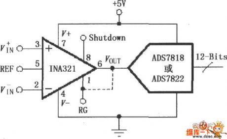
Due the INA321/322 output is in low in resistance, the high-frequency work can directly drive capacitive loads. Input voltage is amplified and output by INA321/322, then it is sent to the 12 - bit high - speed low-power sampling A / D converter ADS7818 or ADS7822. ADS7818 or ADS7822 internal input terminal is the capacitor array (CDAC) digital-analog converter, that is a capacitive input, A / D converter converts the input analog signal to 12-bit digital signal output.
(View)
View full Circuit Diagram | Comments | Reading(1014)
The distributed power supply system circuit diagram
Published:2012/11/9 20:14:00 Author:Ecco | Keyword: distributed power supply , system
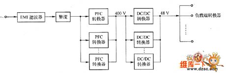
The system consists of a front - end converter and back-end converter: front - end converter (Front End Converter) inlcudes AC / DC converter with power factor correction (PFC) and 400/ 48 V DC / DC converter, both of them are composed of several modules connected in parallel. AC input voltage is rectified by the PFC converter to get 400V DC voltage.
(View)
View full Circuit Diagram | Comments | Reading(1581)
Low-distortion two-phase oscillator circuit diagram
Published:2012/11/9 20:23:00 Author:Ecco | Keyword: Low-distortion, two-phase oscillator
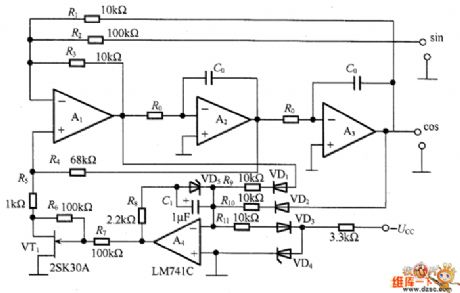
In the circuit, A1 is used as inverting amplifier, the input-output phase difference is 180°, the integrators A2 and A3 have 90 ° phase shift, therefore, the entire circuit has a phase lag of 360 °, if the loop gain is greater than 1, the circuit will generate oscillation. In order to get the oscillation stability, the R5 and VT1 leakage - source equivalent resistors are connected in series.
(View)
View full Circuit Diagram | Comments | Reading(1709)
Simple two-phase oscillator circuit diagram
Published:2012/11/9 20:33:00 Author:Ecco | Keyword: two-phase oscillator
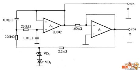
In order to get sine and cosine waves, the circuit is oscillation stabilization circuit without automatic gain control loop, and it can get a stable oscillation output when it is in low frequency. This two-phase oscillator is commonly used as the AC motor signal generator, and it can also be used for the rectangular coordinate transform source or graphic display on the X-Y monitor. In the circuit, A1 constitutex a low pass filter circuit, A2 is an integrator.
(View)
View full Circuit Diagram | Comments | Reading(1538)
Homemade mini - amplifier and speaker circuit diagram
Published:2012/11/9 19:28:00 Author:Ecco | Keyword: mini - amplifier, speaker
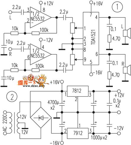
The amplifier part uses fidelity Manifold TDA1521, and its peripheral integrated circuit is extremely simple, and it has overheating, squelch, short circuit and other protection circuits, and it is suitable for homemade beginners. The first class uses the NE5532 for 10 times line amplifier. The coupling capacitor can use domestically CBB capacitors or tantalum capacitors. The previous level power can be gotten by 7815,7915 regulator, and the power transformer should use more than 30W. Bridge rectifier can use 3A full bridge. Amplifier part is shown in Figure 1, the power part of the circuit is shown in Figure 2.
(View)
View full Circuit Diagram | Comments | Reading(3041)
BA1404 HI-FI Stereo FM Transmitter 88 - 108 MHz
Published:2012/11/9 20:33:00 Author:muriel | Keyword: BA1404 , HI-FI, Stereo , FM Transmitter , 88 - 108 MHz

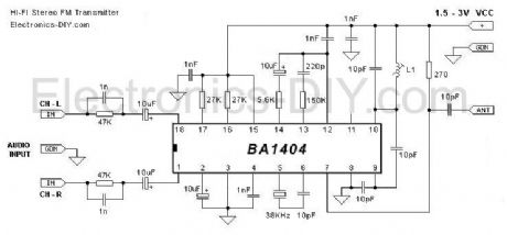
BA1404 Stereo FM Transmitter Components:
BA1404 IC38KHz Crystal L1 - 3.5 Turns Variable Coil 1x PCB 1x 38KHz Crystal Oscillator 1x DIP-18 IC Socket 1x 3.5T Variable Precision RF Coil 1x 10uH Inductor 4x 10uF/50V Gold Audio Capacitors 4x 1nF Ceramic Capacitors 2x 1nF Mylar Capacitors 1x 220pF Ceramic Capacitor 5x 10pF Ceramic Capacitors 2x 47K 1% Metal Film Resistors 2x 27K 1% Metal Film Resistors 1x 150K 1% Metal Film Resistor 1x 5.6K 1% Metal Film Resistor 1x 270 1% Metal Film Resistor (View)
View full Circuit Diagram | Comments | Reading(1716)
Garden Timer with Remote control
Published:2012/11/9 20:31:00 Author:muriel | Keyword: Garden Timer, Remote control
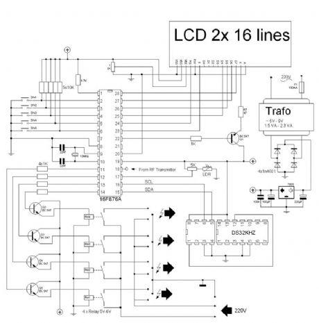
Few years ago we control the lights in the garden with a automatic-timer-switch, very nice but when the evening gets longer or shorter we had to adapt the timer each week. In that time I came in contact with programming microprocessors so my first project was born. The first garden timer was a simple 1 output. The timing was controlled by the PIC and every month I had to change the minutes. So back to the table and design the second garden timer able to control 3 relays - left, mid and right side of the garden. It provided also 4 modes: � always off � always on � from dusk to dawn � from dusk to timer and the timing was dedicated to a RTC DS1307. (View)
View full Circuit Diagram | Comments | Reading(1184)
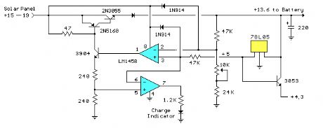
Voltage Regulators (13.6 volts)
Published:2012/11/9 20:28:00 Author:muriel | Keyword: Voltage Regulators, 13.6 volts
View full Circuit Diagram | Comments | Reading(664)
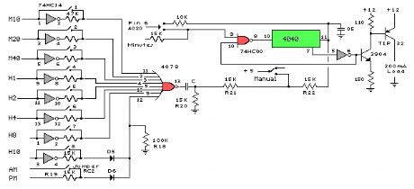
Clock Timer Circuits
Published:2012/11/9 20:27:00 Author:muriel | Keyword: Clock Timer Circuits
View full Circuit Diagram | Comments | Reading(742)
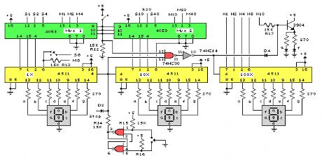
Clock Display Circuits
Published:2012/11/9 20:26:00 Author:muriel | Keyword: Clock Display Circuits
View full Circuit Diagram | Comments | Reading(1019)
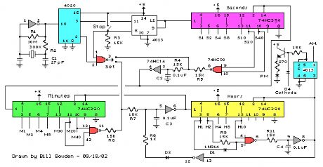
Basic Clock Circuit
Published:2012/11/9 20:25:00 Author:muriel | Keyword: Basic Clock Circuit
View full Circuit Diagram | Comments | Reading(892)
| Pages:279/2234 At 20261262263264265266267268269270271272273274275276277278279280Under 20 |
Circuit Categories
power supply circuit
Amplifier Circuit
Basic Circuit
LED and Light Circuit
Sensor Circuit
Signal Processing
Electrical Equipment Circuit
Control Circuit
Remote Control Circuit
A/D-D/A Converter Circuit
Audio Circuit
Measuring and Test Circuit
Communication Circuit
Computer-Related Circuit
555 Circuit
Automotive Circuit
Repairing Circuit