
Circuit Diagram
Index 269
2 Watt Amplifier
Published:2012/11/19 21:33:00 Author:muriel | Keyword: 2 Watt , Amplifier
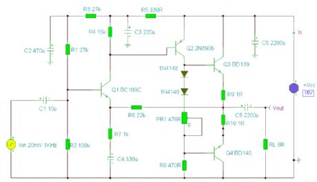
A 2 Watt audio amplifier made from discrete components. (View)
View full Circuit Diagram | Comments | Reading(1093)
Motorcycle Alarm No.8
Published:2012/11/19 21:32:00 Author:muriel | Keyword: Motorcycle Alarm
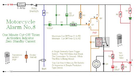
This is a simple motorcycle alarm - with a time limit on the siren. While the thief continues to move the bike - and the normally-open trigger switch continues to open and close - the siren will continue to sound. When the bike stops moving - the siren will cut-off. If Sw1 is open when the thief abandons the bike - the siren will shut off after about ten seconds. If the switch is closed when the bike is abandoned - the siren will turn off after about a minute. Any subsequent movement will re-activate the alarm. (View)
View full Circuit Diagram | Comments | Reading(1089)
Motorcycle Alarm No.7
Published:2012/11/19 21:31:00 Author:muriel | Keyword: Motorcycle Alarm
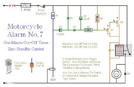
This is a simple motorcycle alarm - with a time limit on the siren. While the thief continues to move the bike - and the normally-open trigger switch continues to open and close - the siren will continue to sound. When the bike stops moving - the siren will cut-off. If Sw1 is open when the thief abandons the bike - the siren will shut off after about ten seconds. If the switch is closed when the bike is abandoned - the siren will turn off after about a minute. Any subsequent movement will re-activate the alarm. (View)
View full Circuit Diagram | Comments | Reading(877)
Power Failure Alarm
Published:2012/11/19 21:30:00 Author:muriel | Keyword: Power Failure, Alarm
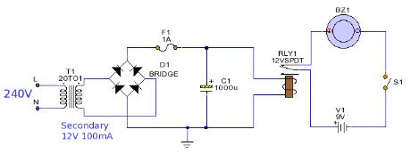
This is a very basic alarm designed to let you know when the electricity supply fails. The alarm is powered from a battery which uses no current consumption at all in standby, a battery should therefore last its full shelf life. (View)
View full Circuit Diagram | Comments | Reading(2391)
3 Zone Duress Alarm
Published:2012/11/19 21:30:00 Author:muriel | Keyword: 3 Zone , Duress Alarm
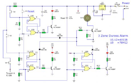
This is a 3 zone alarm for use in high risk areas or possible duress situations. Typical examples being banking or betting booths. The alarm consists of 3 normally open push button switches which can be hidden or in plain view. Once pressed the alarm will latch and a LED will light showing which zone has pressed the alarm. (View)
View full Circuit Diagram | Comments | Reading(962)
Two-Zone Intruder Alarm
Published:2012/11/19 21:29:00 Author:muriel | Keyword: Two-Zone , Intruder Alarm
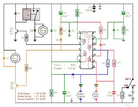
This is a two-zone alarm - with automatic exit, entry and siren cut-off timers. It can be triggered by the usual types of normally-closed input devices - such as magnetic reed contacts - foil tape - PIRs etc. I've used a 12-volt supply in the diagram - but the circuit will work at anything from 9 to 15-volts. All you need do is select a siren, buzzer and relay to suit the voltage you want to use. (View)
View full Circuit Diagram | Comments | Reading(1189)
6 Zone Alarm
Published:2012/11/19 1:40:00 Author:muriel | Keyword: 6 Zone, Alarm
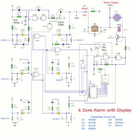
This alarm system has 6 independent zones, 1 timed entry/exit zone, a 7 segment LED display and a test or walkthrough facility. Suitable for a small office or home environment, it can also be adapted to use a combination lock or keypad to set and reset the alarm. (View)
View full Circuit Diagram | Comments | Reading(1202)
Hijack Alarm No. 3
Published:2012/11/19 1:39:00 Author:muriel | Keyword: Hijack Alarm
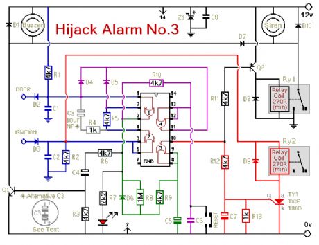
Like the first two Hijack Alarms - this circuit was designed primarily for the situation where a hijacker forces the driver from the vehicle. If a door is opened while the ignition is switched on - the circuit will trip. After a few minutes delay - when the thief is at a safe distance - the Siren will sound. Where it differs from the first two alarms - is in what happens next. I'm obliged to Victor Montanez from the USA who suggested that the engine cut-out should not operate - until the vehicle comes to a stop. That way - the engine will not fail suddenly or unexpectedly. And the hijacker will retain control. I haven't been able to implement Victor's excellent suggestion completely - because I couldn't think of a simple, reliable and universally applicable way of sensing when the vehicle has come to a stop. (View)
View full Circuit Diagram | Comments | Reading(700)
Security Monitor
Published:2012/11/19 1:38:00 Author:muriel | Keyword: Security Monitor

A remote listening circuit. The area to be monitored is connected via a cable and allows remote audio listening. (View)
View full Circuit Diagram | Comments | Reading(1092)
Car Alarm and Immobilizer 2
Published:2012/11/19 1:37:00 Author:muriel | Keyword: Car Alarm, Immobilizer
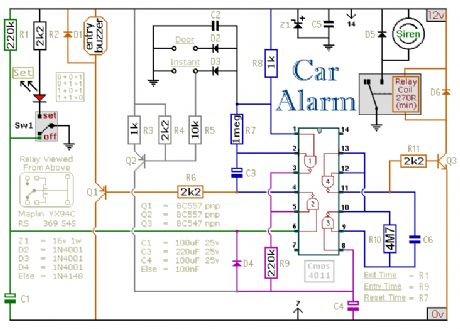
This circuit features exit and entry delays, an instant alarm zone, an intermittent siren output and automatic reset. By adding external relays you can immobilize the vehicle and flash the lights.
(View)
View full Circuit Diagram | Comments | Reading(1075)
Battery Powered Burglar Alarm
Published:2012/11/19 1:36:00 Author:muriel | Keyword: Battery Powered, Burglar Alarm
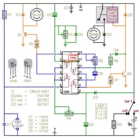
This is a single zone alarm - with independently adjustable Exit, Entry and Siren Cut-Off timers. It will accommodate the usual types of normally-closed input devices - such as magnetic-reed contacts, foil tape and PIRs. When the alarm is activated - the Siren will sound for up to 20-minutes. Then it will switch off - and remain off. The alarm will not re-activate. If you wish - you can use a mains power supply. But the extremely low standby current makes battery power a realistic option. I've used a 9-volt supply in the drawing - but the circuit will work at anything from 5 to 15-volts. All you need do is select a Siren, Buzzer, and Relay to suit the voltage you're using. (View)
View full Circuit Diagram | Comments | Reading(963)
One Time Only Alarm
Published:2012/11/19 1:35:00 Author:muriel | Keyword: One Time Only , Alarm
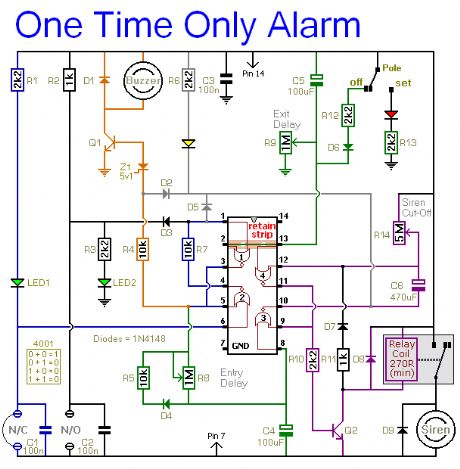
This alarm is designed to sound its Siren only once. That is - when the alarm is activated - the Siren will sound for a preset length of time. Then it will switch off and remain off. The alarm will not re-activate.The basic circuit has a single zone with independently adjustable Exit and Entry delays. The zone will accommodate the usual types of normally-open and normally-closed input devices - such as pressure mats, magnetic-reed contacts, micro switches, foil tape and PIRs.A range of Expansion Modules allow you to add any number of Instant Alarm Zones, Personal Attack Zones and Tamper Zones to your system. There's also an Untimed Output Module. It will keep an internal sounder, strobe-light, lamp or whatever going after the siren has stopped. (View)
View full Circuit Diagram | Comments | Reading(842)
Multi-Zone Transistor Alarm
Published:2012/11/19 1:34:00 Author:muriel | Keyword: Multi-Zone, Transistor, Alarm
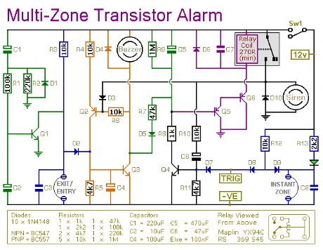
This is a simple transistor-based burglar alarm circuit. Its features include automatic Exit and Entry delays - together with a timed Bell cut-off and Reset. It's designed to be used with the usual types of normally-closed input devices such as - magnetic-reed contacts - micro switches - foil tape - and PIRs. The basic alarm has an Exit/Entry zone and an Instant zone. This will be adequate in many situations. However - larger buildings are best divided into a number of smaller zones. The design allows you to Add As Many Zones As You Like to the basic system. They are Instant Zones - and may be triggered by both normally-open and normally-closed input devices. (View)
View full Circuit Diagram | Comments | Reading(1072)
An SCR Based Burglar Alarm
Published:2012/11/19 1:32:00 Author:muriel | Keyword: SCR , Based Burglar, Alarm
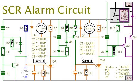
This is a simple SCR based burglar alarm circuit. Its features include automatic Exit and Entry delays - together with a timed Bell cut-off and Reset. It's designed to be used with the usual types of normally-closed input devices such as - magnetic-reed contacts - micro switches - foil tape - and PIRs. The basic alarm has a single zone with Exit/Entry delays. This will be adequate in many situations. However - larger buildings are better divided into zones. The modular design means that you can Add Any Number Of Zones to the system. These Instant zones may be triggered by normally-open as well as normally-closed input devices. (View)
View full Circuit Diagram | Comments | Reading(1063)
Shed/Garage Alarm
Published:2012/11/19 1:31:00 Author:muriel | Keyword: Shed/Garage Alarm
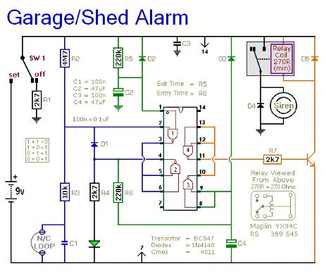
This is a simple single-zone burglar alarm circuit. Its features include automatic Exit and Entry delays. It's designed to be used with the usual types of normally-closed input devices such as - magnetic-reed contacts - micro switches - foil tape - and PIRs. It has an extremely small standby current - making it ideal for battery-powered operation. I've used a 9-volt battery in the diagram - but the circuit will work at anything from 5 to 15-volts. Just choose a relay and Siren suitable for the voltage you want to use. (View)
View full Circuit Diagram | Comments | Reading(811)
Automatic Intruder Alarm
Published:2012/11/19 1:30:00 Author:muriel | Keyword: Automatic Intruder , Alarm
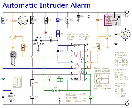
This is a simple single-zone burglar alarm circuit. Its features include automatic Exit and Entry delays and a timed Bell/Siren Cut-Off. It's designed to be used with the usual types of normally-closed input devices such as - magnetic reed contacts - micro switches - foil tape - and PIRs. But it can be Easily Modified to accept normally-open triggering devices - such as pressure mats. (View)
View full Circuit Diagram | Comments | Reading(790)
MotorCycle Alarms 5 & 6
Published:2012/11/19 1:30:00 Author:muriel | Keyword: MotorCycle Alarms
These are two - easy to build - relay-based alarms. You can use them to protect your motorcycle - but they have many more applications. If you use relays with 6-volt coils - they'll protect your Classic Bike . Both alarms are very small. The completed boards occupy about half a cubic-inch - 8 cc. The standby current is zero - so they won't drain your battery. (View)
View full Circuit Diagram | Comments | Reading(779)
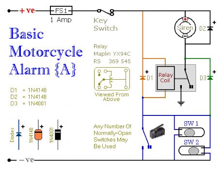
Simple Motorcycle Alarm
Published:2012/11/19 1:29:00 Author:muriel | Keyword: Simple, Motorcycle Alarm
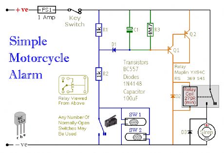
This is a simple - easy to build - transistor based motorcycle alarm. It's designed to work at 12-volts. But - if you change the relay for one with a 6-volt coil - it'll protect your Classic Bike . The standby current is virtually zero - so it won't drain your battery. (View)
View full Circuit Diagram | Comments | Reading(917)
Motorcycle Alarm No. 3
Published:2012/11/19 1:28:00 Author:muriel | Keyword: Motorcycle Alarm
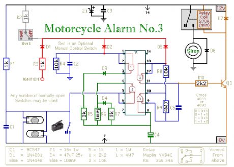
This circuit features an intermittent siren output and automatic reset. It can be operated manually using a key-switch or a hidden switch; but it can also be wired to set itself automatically when you turn-off the ignition. By adding external relays you can immobilize the bike, flash the lights etc. (View)
View full Circuit Diagram | Comments | Reading(1311)
Motorcycle Alarm No. 2
Published:2012/11/19 1:26:00 Author:muriel | Keyword: Motorcycle Alarm
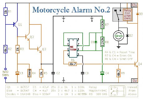
This circuit features an intermittent siren output and automatic reset. It can be operated manually using a key-switch or a hidden switch; but it can also be wired to set itself automatically when you turn-off the ignition. By adding external relays you can immobilize the bike, flash the lights etc. Ron has used my Asymmetric Timer as the basis for his design. (View)
View full Circuit Diagram | Comments | Reading(909)
| Pages:269/2234 At 20261262263264265266267268269270271272273274275276277278279280Under 20 |
Circuit Categories
power supply circuit
Amplifier Circuit
Basic Circuit
LED and Light Circuit
Sensor Circuit
Signal Processing
Electrical Equipment Circuit
Control Circuit
Remote Control Circuit
A/D-D/A Converter Circuit
Audio Circuit
Measuring and Test Circuit
Communication Circuit
Computer-Related Circuit
555 Circuit
Automotive Circuit
Repairing Circuit