
Circuit Diagram
Index 267
200mW Amplifier
Published:2012/11/21 1:44:00 Author:muriel | Keyword: 200mW , Amplifier
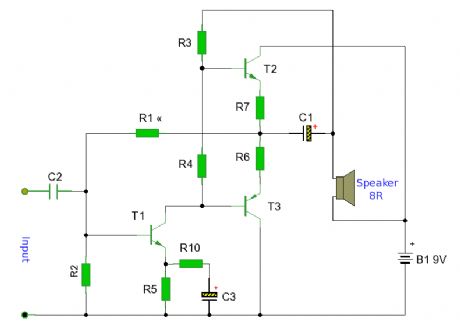
A small battery driven amplifier with 200mW output. This is a suitable amplifier for portable radios and other battery powered equipment. (View)
View full Circuit Diagram | Comments | Reading(990)
32 Watt Amplifier
Published:2012/11/21 1:43:00 Author:muriel | Keyword: 32 Watt, Amplifier
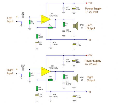
A 32 Watt per channel stereo power amplifier made using the TDA2050V monolithic integrated circuit. (View)
View full Circuit Diagram | Comments | Reading(1084)
24 Watt Class A Amplifier
Published:2012/11/21 1:42:00 Author:muriel | Keyword: 24 Watt , Class A , Amplifier
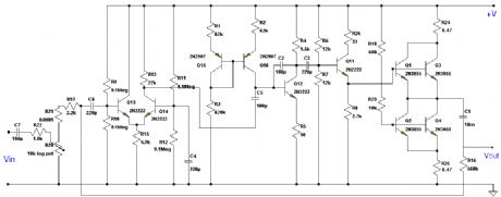
A 24 Watt Class A Amplifier made from discrete semiconductors, built and tested by Marc Klynhans from South Africa. (View)
View full Circuit Diagram | Comments | Reading(1107)
Three Band Active Tone Control
Published:2012/11/21 1:41:00 Author:muriel | Keyword: Three Band, Active Tone, Control
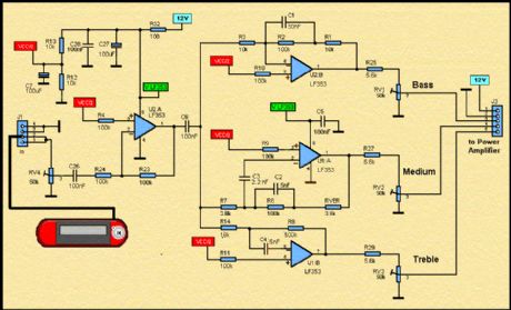
Here, it is a diagramm of an active loudspeaker. The LF353 of, National Semiconductor, is going to split audio signal into three bands. SANYO'S LA47536 is going to amplify these signals. In stereo mode, we shall have the action of eight high speakers who are going to create a very important sound pressure. (View)
View full Circuit Diagram | Comments | Reading(0)
The GEM: Class-A//AB Amplifier
Published:2012/11/21 1:40:00 Author:muriel | Keyword: Class-A//AB, Amplifier
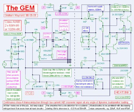
The GEM is an audio power amplifier embodying simultaneously active Class A and Class AB output stages for 100+ Watts into a 4 ohm loudspeaker. The front end pcb will drive up to 100+W variants, or the 200+ Watts version into a 4 ohm loudspeaker load. (View)
View full Circuit Diagram | Comments | Reading(1314)
Buffer Amplifier
Published:2012/11/21 1:39:00 Author:muriel | Keyword: Buffer Amplifier
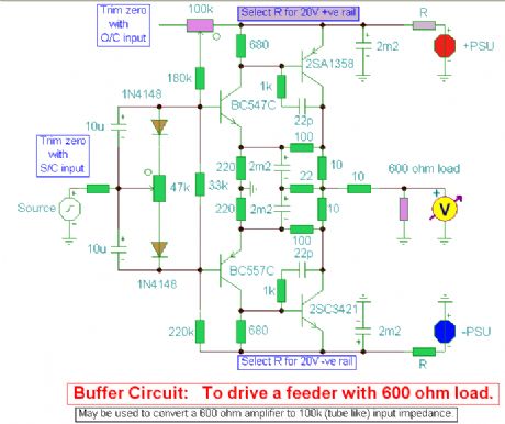
A hifi preamplifier designed to convert high output impedance amplifiers to 600 ohm outputs. (View)
View full Circuit Diagram | Comments | Reading(1612)
Resistor detected motor reversing control circuit
Published:2012/11/20 21:10:00 Author:Ecco | Keyword: Resistor detected motor , reversing control
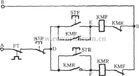
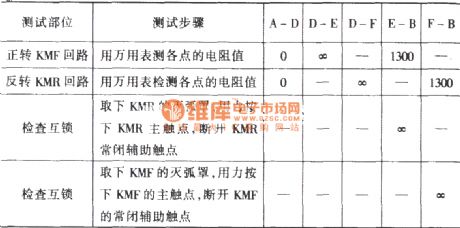
Motor reversing control circuit has more joints, so it is easy to make mistakes in the newly installed or renovated cases. Resistor method for detection can avoid accidents, and the circuit is shown in the figure. The multimeter dial in R × 100Ω stopper, under normal circumstances, the values between the various points of the circuit are shown in the following table.
(View)
View full Circuit Diagram | Comments | Reading(785)
Eight-way remote control transmitter CS901
Published:2012/11/20 21:07:00 Author:Ecco | Keyword: Eight-way , remote control, transmitter
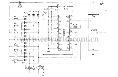
The keys SA1 ~ SA8 and diodes VD1 ~ VD13 form Octal matrix input circuit for the eight encoded input circuit of remote control transmitter circuit. Because the SM5262's pin 7 to 13 are used for the address / data common terminals, if ther are used as the data input terminals, the circuit has a total of six data input terminals, when all of them are used for data input, they can form a total of 26 = 64, i.e. 64-channel remote control transmitter.
(View)
View full Circuit Diagram | Comments | Reading(1052)
The Anti Shake circuit with NAND gate
Published:2012/11/20 21:04:00 Author:Ecco | Keyword: Anti Shake, NAND gate
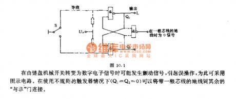
Dither signal may occur in the conversion of digital electronic signal from chain mechanical switch, and it may cause misoperation, so the illustrated circuit may be used for this.
(View)
View full Circuit Diagram | Comments | Reading(837)
Pressure gauge circuit with magnetic components
Published:2012/11/20 20:30:00 Author:Ecco | Keyword: Pressure gauge, magnetic components
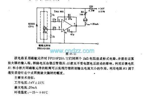
The circuit uses magnetic components FP210P250, and they form a bridge circuit with two 1kΩ resistors and connected to the input terminal of the operational amplifier. Bridge voltage is stablized by regulator in order to make it independent from supply voltage fluctuations. It uses the distance between feedback resistors R1 and small iron piece magnetic components to realize stroke control the size of the output current.
(View)
View full Circuit Diagram | Comments | Reading(1365)
Great Wall programmed box fan circuit
Published:2012/11/20 20:34:00 Author:Ecco | Keyword: Great Wall , programmed box fan
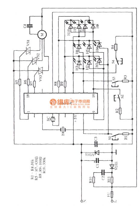
Great Wall FS36-40 fan uses programmable technology, and it has three wind species, three wind speeds and four-time segment timing shutdown function. It also has 10W lights at night, and the circuit is shown as the figure. The circuit uses IC chip RTS-1A with fewer external components and manual operation and automatic operation. H1 ~ H10 are light emitting diodes.
(View)
View full Circuit Diagram | Comments | Reading(1699)
Automatically series reactance start three-phase motor circuit 2
Published:2012/11/20 0:39:00 Author:Ecco | Keyword: Automatically, series reactance, start, three-phase motor
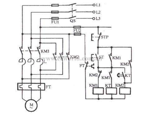
As shown in figure, pressing the start button ST, then the KM1 coil will pull in, and the main contacts are connected to reactors group L, the motor M gets to the buck start state. At the same time, due to the closure of the the KM1 auxiliary contacts, time relay KT gets electric timing. When the delay time reaches KT's tuning time, KT contacts are closed, KM2 coil gets electric, the normally closed contact cuts KM1 coil loop, then the KT coils have also de-energized, KM2 normally open contact action to protect themselves.
(View)
View full Circuit Diagram | Comments | Reading(1115)
Homemade fast hand dryer circuit
Published:2012/11/20 1:27:00 Author:Ecco | Keyword: Homemade, fast hand dryer

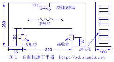

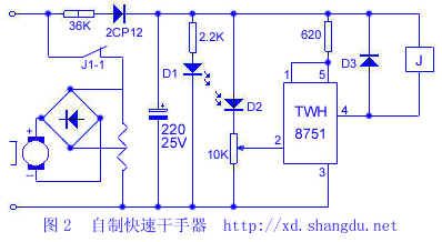
When it is illuminated, the IC's pin 1 is in high potential, TWH8751 is cutoff, J loses power, J1-1 disconnects. When the hand gets into and blocks the light, D2 shows a large resistance, pin 2 of the IC is in a low potential, the IC output end gets conduction, J1-1 is turned on, the electric wire and the motor are energized.
(View)
View full Circuit Diagram | Comments | Reading(1947)
Three-phase motor speed measured with a multimeter
Published:2012/11/20 1:58:00 Author:Ecco | Keyword: Three-phase , motor speed , multimeter
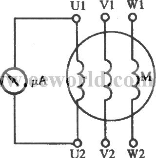
In the Figure, μA uses the multimeter 50μA block ( it is also available to use 1mA block ). It is connected with any winding of three-phase stator windings, then slowly turning the motor rotor can make rotor run in the uniform speed. There is always a certain amount of remanent magnetization of the used motor, when the rotor is rotated, the magnetic force will cut lines, then the electromotive force is induced in the stator windings, there is current flowing through the ammeter swing.
(View)
View full Circuit Diagram | Comments | Reading(1622)
Single phase shaded pole motor commutation circuit
Published:2012/11/20 2:17:00 Author:Ecco | Keyword: Single phase , shaded pole, motor commutation
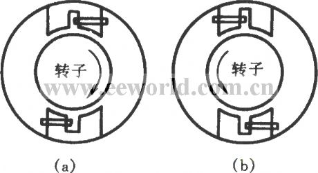
Due to the stator structure and particularity of working principle, shaded pole motor can not use interchangeable winding terminals to change direction like the split-phase capacitor motor. The shaded pole motor's shaded pole split-phase effect can make the original magnetic field without rotating nature change into an approximation rotating magnetic field.
(View)
View full Circuit Diagram | Comments | Reading(1316)
Water tower automatic water supply protection circuit
Published:2012/11/20 2:21:00 Author:Ecco | Keyword: Water tower , automatic water supply rotection
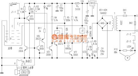
VT1, VT2, VT3, J1 are the main components of the pumping circuit, the working principle is not difficult to make a self- analysis for reader. Water protection circuit is mainly composed of the probe D and VT4, if the pumping time interval is too long, the tube memory water leakage is below D, and the water circuits A , D are open, VT4 gets saturated conduction, so that VT1 base pole clamp is at low potential. When the towers level falls to the lower limit B or less, due to the extremely low level of VT1 base, it can not be turned and therefore can not pumping.
(View)
View full Circuit Diagram | Comments | Reading(1505)
Op-Amp Mic Preamp
Published:2012/11/19 23:47:00 Author:muriel | Keyword: Op-Amp, Mic, Preamp
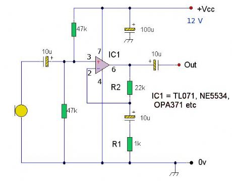
A high quality microphone preamplifier using a single power supply, suitable for dynamic or electret microphones. The op-amp used can be any low noise, high performance type, e.g. NE5534,TL071, OPA 371 etc (View)
View full Circuit Diagram | Comments | Reading(2599)
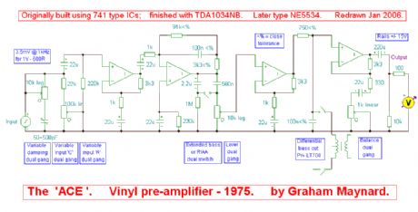
Vinyl Pre-Amplifier
Published:2012/11/19 23:44:00 Author:muriel | Keyword: Vinyl , Pre-Amplifier
View full Circuit Diagram | Comments | Reading(1025)
The GEM Class-A//AB Amplifier
Published:2012/11/19 23:43:00 Author:muriel | Keyword: GEM, Class-A//AB , Amplifier
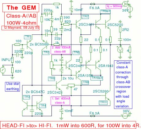
A Class A // Class AB amplifier rated 100 Watts when driving a 4 ohm loudspeaker. (View)
View full Circuit Diagram | Comments | Reading(1302)
Headphone Amplifier
Published:2012/11/19 23:42:00 Author:muriel | Keyword: Headphone, Amplifier
An amplifier to drive low to medium impedance headphones built using discrete components. (View)
View full Circuit Diagram | Comments | Reading(0)
| Pages:267/2234 At 20261262263264265266267268269270271272273274275276277278279280Under 20 |
Circuit Categories
power supply circuit
Amplifier Circuit
Basic Circuit
LED and Light Circuit
Sensor Circuit
Signal Processing
Electrical Equipment Circuit
Control Circuit
Remote Control Circuit
A/D-D/A Converter Circuit
Audio Circuit
Measuring and Test Circuit
Communication Circuit
Computer-Related Circuit
555 Circuit
Automotive Circuit
Repairing Circuit