
Circuit Diagram
Index 323
Simple water detector circuits
Published:2012/9/24 4:07:00 Author:muriel | Keyword: water, detector

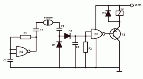
This simple water detector circuit uses alternative voltage in order to prevent the corrosion of the electrodes. It is easy to build and uses N1 as a trigger Schmitt gate which generate the AC. If between the electrodes is a electricity conductor, for example an aqueous solution, then because of the rectification action of D1 and D2, the C4 capacitor is charging.When the capacitor voltage reaches switching threshold of the N2 trigger Schmitt, the relay will trigger and connect, for example a drain pump. The pump will be disconnected as soon as the electrodes won’t touch the liquid.
Simple water detector circuit schematic
Water detector componentsR1 = 470KR2 = 10M … 22MC1 … C4 = 2.2nFN1, N2 = 1/2 4093D1 … D3 = 1N4148T1 = pnp transistor (BC557)?
10 Responses to “Simple water detector circuit”
(View)
View full Circuit Diagram | Comments | Reading(1561)
Simple water detector circuit
Published:2012/9/24 4:06:00 Author:muriel | Keyword: water, detector
This simple water detector circuit uses alternative voltage in order to prevent the corrosion of the electrodes. It is easy to build and uses N1 as a trigger Schmitt gate which generate the AC. If between the electrodes is a electricity conductor, for example an aqueous solution, then because of the rectification action of D1 and D2, the C4 capacitor is charging.When the capacitor voltage reaches switching threshold of the N2 trigger Schmitt, the relay will trigger and connect, for example a drain pump. The pump will be disconnected as soon as the electrodes won’t touch the liquid.
Simple water detector circuit schematic
Water detector componentsR1 = 470KR2 = 10M … 22MC1 … C4 = 2.2nFN1, N2 = 1/2 4093D1 … D3 = 1N4148T1 = pnp transistor (BC557)?
10 Responses to “Simple water detector circuit”
(View)
View full Circuit Diagram | Comments | Reading(292)
LM317 audio amplifier
Published:2012/9/24 4:06:00 Author:muriel | Keyword: audio, amplifier
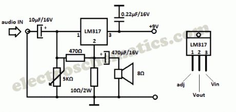
You probably know that LM317 IC is used as an adjustable voltage regulator, but did you know it can be used as an audio amplifier? This is a class A audio amplifier built with LM317 that delivers a maximum 1W audio power.
Use a good heatsink for the LM317 IC and adjust the 5K variable resistor so that you have 4.5V on 10Ω resistor (or LM317 pin 2, Vout).
LM317 amplifier schematic
Source: vegmatic1966′s Youtube Channel
Video explanation of the working principle
?
19 Responses to “LM317 audio amplifier”
(View)
View full Circuit Diagram | Comments | Reading(2958)
Solar Battery Charger Circuits
Published:2012/9/24 4:05:00 Author:muriel | Keyword: Solar, Battery Charger
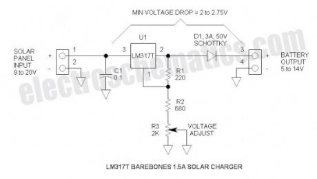
This is the most simple and affordable solar battery charger that the hobbyist can make. It has a few drawbacks over other similar controls, but offers numerous advantages. It is intended for charging lead-acid batteries, but may also be used for charging any battery at a constant voltage. Voltage output is adjustable.Advantages & Disadvantages of this solar charger
+ Simple, small & inexpensive
+ Uses commonly available components
+ Adjustable voltage
+ ZERO battery discharge when sun is not shining
– High drop-out voltage—may be marginal for 6V application
– Current limited to 1.5A
– No LED indicators—no bells or whistles
Solar battery charger specifications
Solar panel rating: 20W (12V) or 10W (6V)
Output voltage range: 5 to 14V (adjustable) (may be reduced further by shorting R2)
Max power dissipation: 10W (includes power dissipation of D1)
Typical dropout voltage: 2 to 2.75V (depending upon load current)
Maximum current: 1.5A (internally limits at about 2.2A)
Voltage regulation: ±100mV (due to regulation of series rectifier)
Battery discharge: 0mA (this control will not discharge the battery when the sun doesn’t shine)
Solar battery charger schematic
6V Applicaton
Output Voltage: Set for 7V
Input voltage:
Battery discharged (6V): 8.75V Min @ 1.5A (this is a little high for panels that are characterized for 6V applications)
Battery charged (7V): 9V Min @ 10mA (e.g.)
12V Application
Output Voltage: Set for 14V
Input voltage:
Battery discharged (12V): 14.75V Min @ 1.5A (Available from solar panel characterized for 12V operation)
Battery charged: (14V): 16V Min
Minimum Head Voltage
This is also referred to “drop-out voltage.” The input voltage must exceed the output voltage by about 2.75V @ 1.5A. Fortunately, when the battery discharged, the output voltage is lower so the solar panel voltage will also be lower.
When fully charged, the battery voltage will be high, but the current is very low—at this point, the drop-out voltage reduces to about 2V and the open circuit solar panel voltage also comes into play. The schottky rectifier was selected to reduce this head voltage requirement—the voltage drop of the schottky is about 0.5V @ 1.5A or about half that of a typical silicon rectifier.
More advanced controls have a much lower head voltage requirement and will function better under marginal conditions.
Maximum Power Dissipation
The power is limited by the thermal resistances of both the LM317T and the heat sink. To keep the junction temperature below the 125°C Max, the power must be limited to about 10W. If a smaller or less effective heat sink is used, the maximum power dissipation must be de-rated. Fortunately, the LM317 has internal temperature limiting so that if it gets too hot, it shuts down thus protecting itself from damage. Max power comes into effect when charging a 12V battery @ 1.5A: e.g. battery voltage = 12V, solar panel = 18V. P = (18V – 12V) * 1.5A = 9W. So thermally, it is carefully matched to the current rating.
If a solar panel that is characterized for 12V is applied with a 6V battery, the maximum current must be reduced to about 0.7A: e.g. battery voltage = 6V, solar panel voltage = 18V. P = (18V – 6V) * 0.7A = 9.6W. In this case, (View)
View full Circuit Diagram | Comments | Reading(3702)
Sound Level Meter Circuit
Published:2012/9/24 4:04:00 Author:muriel | Keyword: Sound, Level Meter
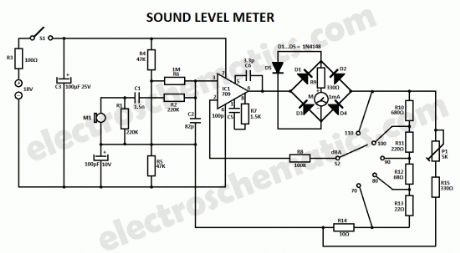
This sound level meter circuit can be used to control the intensity of a sound recording or in a disco. It has 5 measurement domains between 70 and 120 dB; reading accuracy is 0.5 dB. Microphone M1 is used to receive the acoustic signal and is coupled to C1, C2, R1 and R2. This components, together with the microphone’s capacity and with the input impedance of the amplifier form an input filter. The filtered signal goes to operational amplifier IC1 whose sensitivity can be switched with S2 corresponding to the five measuring domains.D1 … D4 diodes rectifies the alternating voltage at the amplifier output and feeds the indicator tool through R9. D5 is used in order to protect the sound level meter indicator against high voltages; it limits the rectifier’s output voltage when the sound level is too high.
On normal conditions the input current is about 2 mA that is why the circuit can be powered with 2 x 9V batteries. S1 switch is used to disconnect the sound level meter device after measurement. The indicator tool should have a graded scale in dB with the maximum value of +10.
Sound Level Meter Schematic
?
4 Responses to “Sound Level Meter Circuit”
(View)
View full Circuit Diagram | Comments | Reading(2379)
Simple Arduino LED projects
Published:2012/9/24 4:02:00 Author:muriel | Keyword: Arduino, LED

In this article I will add some simple Arduino LED projects starting with basic ones like how to turn on an LED, blinking, and more. Every step will have the code, the schematic, photos of the project and sometimes a video tutorial.
Let’s start with the simplest led project which consists in turn on an LED. You can use an external one or use the one soldered on the board (pin 13).Turn ON an LED Sketch This is a very simple arduino project where a led is turned on by setting the pin 13 as output, then write it with a high value, in our case that means that pin 13 will deliver 5 volts.void setup() {
pinMode(13, OUTPUT); // set pin 13 as output
digitalWrite(13, HIGH); // set pin 13 as high or 1
}
void loop() {
// left empty
}
If you want to turn on more leds then set other pins as OUTPUT and HIGH.Next lets blink some leds.
Blinking leds sketchvoid setup() {
pinMode(13, OUTPUT); // set pin 13 as output
pinMode(12, OUTPUT); // set pin 12 as output
}
void loop() {
digitalWrite(13, HIGH); // set pin 13 as high or 1
digitalWrite(12, LOW); // set pin 12 as low or 0
delay(1000); // wait 1000 ms
digitalWrite(12, HIGH); // set pin 13 as high or 1
digitalWrite(13, LOW); // set pin 12 as low or 0
delay(1000); // wait 1000 ms
}
“Knight Rider” effect sketchint del=100; // sets a default delay time
void setup() {
// initialize the digital pins as outputs:
for (int i = 2; i<=8 ; i++) {
pinMode(i, OUTPUT);
} // end of for loop
} // end of setup
void loop() {
for (int i = 2; i<=8; i++) { // blink from LEDs 2 to 8
digitalWrite(i, HIGH);
delay(del);
digitalWrite(i, LOW);
}
for (int i = 7; i>=3; i--) { // blink from LEDs 8 to 3
digitalWrite(i, HIGH);
delay(del);
digitalWrite(i, LOW);
}
}
Fading LED sketchint ledPin = 9; // LED connected to digital pin 9
void setup() {
// nothing happens in setup
}
void loop() {
// fade in from min to max in increments of 5 points:
for(int fadeValue = 0 ; fadeValue <= 255; fadeValue +=5) {
// sets the value (range from 0 to 255):
analogWrite(ledPin, fadeValue);
// wait for 30 milliseconds to see the dimming effect
delay(30);
}
// fade out from max to min in increments of 5 points:
for(int fadeValue = 255 ; fadeValue >= 0; fadeValue -=5) {
// sets the value (range from 0 to 255):
analogWrite(ledPin, fadeValue);
// wait for 30 milliseconds to see the dimming effect
delay(30);
}
}
More arduino led projects will be added soon. Thank you!?
2 Responses to “Simple Arduino LED projects”
(View)
View full Circuit Diagram | Comments | Reading(1563)
Simple and Useful LED circuits
Published:2012/9/24 4:02:00 Author:muriel | Keyword: LED
Due to the advantages like low voltages, long life, cheap, reliable, fast on-off switching etc, the LED’s are used in many applications. The various applications of LED are,
All kinds of visual displays i.e. seven segment displays and alpha numeric displays. Such displays are commonly used in the watches and calculators.
In the optical devices such as optocouplers.
As on-off indicator in various types of electronic circuits.
Some LED’s radiate infrared light which is invisible. But such LED’s are useful in remote controls and applications like burglar alarm.
Other simple applications of LED are :
Sometimes you need to know which wire/node is positive polarity and which wire/node is negative polarity.The LED as a polarity indicator circuit is show in above diagram. In the diagram as you can see two LED’s are placed in opposite directions so when one LED is ON the other LED will be OFF. I have used Red and Green LED’s. ?When node A is positive green LED glows while when node B is positive, Red LED glows. This indicates polarity of the input d.c voltage .
The above shown circuit is LED as continuity tester. This circuit is used for checking continuity of cables, connectors and switches. When A and B terminals are shorted, the LED glows due to battery connected inside indicating the presence of continuity.
To prevent the reverse biased destruction rectifier diode D is used. The presence of voltage is instead of ?series resistor, a capacitor is used whose reactance Xc which is ( 1/2 πfC )Ω limits the current. Advantage of using capacitor is that it does not consume any power hence total power dissipation is less.
When fuse is working, it provides short circuit path bypassing LED circuit. So LED is OFF. If fuse opens the line voltage drives the LED through capacitor and thus LED glows. Thus blown fuse condition is indicated.
Not only these there are many useful applications of diode.What do you say..?? ??
8 Responses to “Simple and Useful LED circuits”
(View)
View full Circuit Diagram | Comments | Reading(2196)
The amplifier circuit with macroaxis and low current
Published:2012/9/20 22:00:00 Author:Ecco | Keyword: amplifier , macroaxis, low current
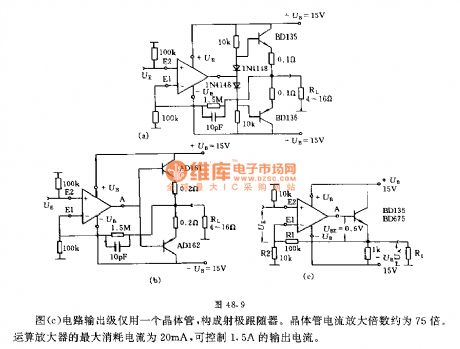
Figure A shows the amplifier circuit using a high-output-power and small-distortion complementary transistor. Two diodes can significantly reduce the controlling dead zone. The emitter of two transistors is connected to a strong negative feedback, the dead zone can be further reduced.The circuit shown in Figure b is simpler than the circuit shown in Figure a, and it also uses strong negative feedback to reduce the dead zone.The output stage of circuit shown in Figure c only uses one transistor to form a emitter follower. The transistor current magnification is about 75 times. The op amp maximum current consumption is 20mA to control 1.5A output current.
(View)
View full Circuit Diagram | Comments | Reading(1376)
Pre-amplifier circuit with a high input resistance
Published:2012/9/20 21:46:00 Author:Ecco | Keyword: Pre-amplifier , high input resistance
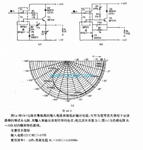
The circuits shown in Figures a and b have a high input resistance and low output resistance, and they can be used as a broadband amplifier for oscilloscopes and other test head circuits. Their input and output have the same potential, the voltage amplification factor is 1. Figure c shows the amplitude and phase characteristic curve when the load resistance RL = 50Ω.The main technical indications:Input resistance (25 ℃ pm ) > 10 9 ΩBroadband frequency (-3dB, load resistor RL = 50 Ω ) > 100MHzOutput resistance of < 10 Ω
(View)
View full Circuit Diagram | Comments | Reading(1332)
Selective amplifier circuit
Published:2012/9/20 21:38:00 Author:Ecco | Keyword: Selective amplifier

The general selective amplifier uses double T network which requires high-precision component parameters. But the circuit shown in Figure can avoid the question. The frequency f0 is determined by C1 at low pass and C2 at high pass.
(View)
View full Circuit Diagram | Comments | Reading(995)
Fuel tank oiling liquid level automatic control circuit with frogs sound
Published:2012/9/20 21:30:00 Author:Ecco | Keyword: Fuel tank, oiling liquid level, automatic control , frogs sound
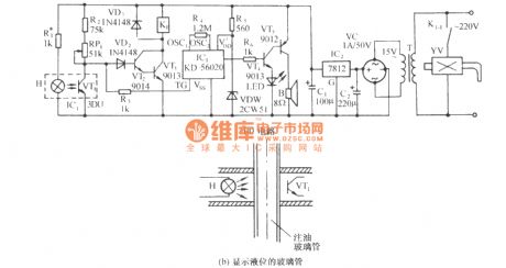
As shown in figure, the circuit is composed of optocoupler, relay control solenoid valve circuit, frogs calling circuit and AC buck rectifier circuit and other components. Typically, the side wall of the tank has a glass tube to display liquid level. If a photocoupler is mounted on the tube ( Figure b ), and it can be moved up and down on the tube, it can achieve the automatic control liquid level of oil filling. When the liquid level reaches the set height, it can also issue frog sound.
(View)
View full Circuit Diagram | Comments | Reading(1506)
Cultural treasures anti-metal closing audible and visual alarm circuit
Published:2012/9/20 21:25:00 Author:Ecco | Keyword: Cultural treasures , anti-metal closing , audible and visual alarm
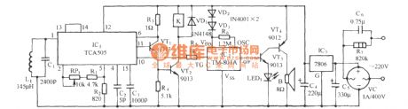
As shown in the figure, the circuit consists of electromagnetic inductive proximity switch, relay control circuit, whistle analog voice circuit and AC buck rectifier circuit. This circuit can be used for prevention of burglary in museum, artifacts or treasures Collection Room. When someone uses metal artifacts to open the cabinet, the circuit will automatically send alarm whistles and start relay control circuit to turn on the light or camera equipment.
(View)
View full Circuit Diagram | Comments | Reading(1717)
Simple Solar Lamp circuit
Published:2012/9/21 3:26:00 Author:Ecco | Keyword: Simple, Solar Lamp
Here is the simple solution to make an automatic Solar powered lamp. It automatically switches on two high power White LEDs in the evening and stays on for 6 hours using a 6 volt 4.5 Ah rechargeable battery.A 12 volt solar panel is used to charge the battery during day time. The battery is connected to the input line through the NO and Common contacts of the relay. Diodes D1 and D2 drops 1.4 volts and charge indicator LED uses 1.8 volts. Relay also drops some voltage so that around 8 volts will be available for charging the battery. The high value (4700uF) Capacitor C1 act as a “buffer” for the clean switching of the relay and also prevents “relay clicking” when the input voltage reduces momentarily.
Simple Solar Lamp Circuit diagram
During day time, the solar panel generates 12 volt DC which makes the relay active and the NO (Normally Open) contact makes connection with the common contact. This completes the current path to the battery. Two 1 Watt power LEDs are connected to the NC (Normally Connected) contacts of the relay. When the relay energize, the NC contact breaks and LEDs do not get power. Resistor R2 ( 18 Ohms 1 Watt) drops the LED current to 330 mA. The LEDs are rated 350 mA at 3.6 volts. With 3 volts and 250 mA current, these LEDs can give adequate brightness.
1 Watt Power LED
In the evening, current from the solar panel stops and relay de – energize. At the same time, the NC contact of the relay gets power from the battery through the common contact and LEDs turn on. Theoretically, the battery can power 12 hours with 350 mA current, but the battery voltage and current reduces drastically. So it is better to turn off the lamp after 5 or 6 hours using the switch S1.Use a small 6 volt 100 Ohms PCB relay to make the lamp unit compact. The Solar Lamp circuit including the relay can be enclosed in a small box. If a reflector is fixed behind the White LEDs, intensity of light can be increased. Use jack and socket to connect the solar panel with the circuit.?
16 Responses to “Simple Solar Lamp circuit”
source: electroschematics.com (View)
View full Circuit Diagram | Comments | Reading(2431)
Power LED Lamp
Published:2012/9/21 3:25:00 Author:Ecco | Keyword: Power , LED Lamp
Here is a High power White LED lamp circuit that gives ample light in a room. It is an energy saving lamp and consumes very little power to give sufficient light. The lamp is directly powered from AC hence it is compact and easy to fix inside the switch board box.The Power LED Lamp circuit uses 1 Watt White LED as the light source. Luxeon type high watt LEDs are now available. It is rated 3.6 volts and consumes maximum 350 milli amperes current. To get sufficient brightness of the LED, more than 200 mA current is required. The AC power is dropped by three 105K (1uF) AC capacitors to low voltage AC. Three capacitors (C1through C3) are connected in parallel to increase current so around 210 mA current will be available.
The low volt AC is then rectified by the bridge comprising D1 through D4 and made ripple free by C4. Since the LED voltage is 3.6 V, Zener diode is used to regulate the DC to a safer level. Capacitor C5 act as a buffer to store current to give maximum brightness to the LED. Resistor R1 removes stored current from the AC capacitors when the circuit is unplugged and resistor R2 protects the circuit from transients and inrush current.
Power LED Lamp Circuit diagram
1 Watt Power LED
Caution: It is important to note that this circuit can give a lethal shock if handled carelessly. Most points are at mains potential, so that take utmost care while handling. Do not construct this if you are not experienced in handling AC circuits. Do not troubleshoot or test when it is connected to mains.?
39 Responses to “Power LED Lamp”
source: electroschematics.com
(View)
View full Circuit Diagram | Comments | Reading(2300)
Battery Status Indicator circuit
Published:2012/9/21 3:25:00 Author:Ecco | Keyword: Battery Status, Indicator
If an LED indicator is present in battery powered gadgets such as Emergency lamps, it will consume power even if the gadget is not using. This will reduce the battery voltage since the LED takes around 2 volts. So it is necessary to charge the battery continuously to keep the battery voltage level. This circuit eliminates this and the LEDs turn on only in two conditions. That is in the over charged and over discharged conditions only.
The circuit is basically a voltage controlled switch using Zener diodes. Two state LED indication is provided using a Bicolour LED. Zener diode ZD1 and the PNP transistor T1 forms the over discharge indicator switch. When the battery voltage is above the breakdown point of ZD1 (around 5 volts), it conducts and keeps T1 out of conduction. So the Red half of the bicolur LED remains off. When the battery voltage reduces below 5 volts, Zener turns off allowing T1 to conduct and Red LED turns on. This indicates that the battery is going to the over discharged state.
Zener diode ZD2 and NPN transistor T2 forms the Over charge indicator switch. When the battery voltage is below 6.8 volts (maximum voltage level), ZD cease to conduct and T2 remains off. So that the Green half of the LED also remains off. When the battery voltage increases above 7 volts due to overcharging, ZD2 conducts followed by T2 and Green LED turns on. This is the over charged state. In short, if the battery voltage is between 5 and 7 volts, both LEDs remain off. This reduces the chance of power consumption.
Battery Status Indicator Circuit
Setting
A variable power supply is necessary for the calibration. Provide 5 volts and adjust VR1 till Red LED turns on. At this point, Green LED remains off. Increase the voltage to 7volts and adjust VR2 till Green LED turns on. At this point, Red LED should remain off. Reduce the voltage to 6 volts. Both LEDs should be in the off state.?
21 Responses to “Battery Status Indicator circuit”
source: electroschematics.com
(View)
View full Circuit Diagram | Comments | Reading(2176)
Battery over discharge Indicator
Published:2012/9/21 3:25:00 Author:Ecco | Keyword: Battery , over discharge , Indicator
Most of the battery voltage indicators always remain on even if the load is off. The LED indicator and the circuit consume current which reduces the battery charge and the charger should be continuously switched on to keep the charge of the battery. Here is an ideal solution to prevent this. The indicator turns on only if the load is running. It gives a Red LED indication when the battery voltage reduces below 4.7 volts. So that the load can be switched off to prevent deep discharge of the battery.
The circuit uses the OpAmp CA3140 as a voltage comparator and SCR 2P4M as switch. The inverting input of IC1 gets half supply voltage(3V) from the potential divider R2-R3 and its non inverting input gets a higher voltage through R1. Capacitor C1 maintains stable voltage level at the non inverting input of IC1.Power supply to the IC is obtained through the SCR 2P4M when the load switches on.
Output voltage of IC1 is used to drive the deep discharge indicator LED.As long as the output voltage from IC1 is above 5 volts, Zener conducts and keep the PNP transistor off. So that LED remains off. When the battery voltage reduces below 5 volts, output voltage of IC1 also reduces to 5 volts or less. This makes the Zener out of conduction and T1 turns on and LED lights to indicate low battery level.
Battery over discharge indicator circuit
Setting
Normally IC1 will be off since SCR is not conducting. The gate of SCR (point A) should be connected after the load switch so that SCR fires only when the load turns on. Before connecting the circuit to the battery, adjust the breakdown point of Zener using a variable power supply. Give 5 volts and slowly adjust VR till LED turns on. This is the breakdown point of Zener. It will be around 5 volts. If Zener is still conducting, reduce its value to 4.1 volts. CA3140 is a low power BiMOS Op Amp and its output will be nearly full supply voltage. Once the SCR triggers, it latches itself and remains conducting even if the gate voltage is removed. SCR can be switched off by removing power through S1.?
3 Responses to “Battery over discharge Indicator”
source: electroschematics.com (View)
View full Circuit Diagram | Comments | Reading(1890)
High Volt LED Flasher
Published:2012/9/21 3:24:00 Author:Ecco | Keyword: High Volt, LED Flasher
Here is a Flasher circuit that directly derives power from AC to give brilliant flashes at the rate of one flash per second. It uses a Diac as the main element to flash the LED through current pulses.
230 Volt AC is reduced to 50 volt DC by the dropping capacitor C1 and is rectified by the full wave bridge D1 through D4.Resistor R1 removes stored current from C1 when the circuit is unplugged and resistor R2 protect the circuit from inrush current.
The main element in the circuit is the Diac DB3.It is a semiconductor device that acts as a Voltage-Controlled switch. If a low voltage is applied to the Diac, it remains as an open switch passing little current. All diacs have a break down voltage VBO which is between 28 volts and 36 volts. If the applied voltage is above the minimum VBO, the Diac enters into the” Negative Resistance” region and heavy current passes through it. Diacs are commonly used in pulse generator circuits for driving SCRs and Triacs.
In the circuit, Diac forms a Relaxation Oscillator along with capacitor C2.When the capacitor C2 gets current, it charges slowly through R3.When the voltage in C2 increases above the VBO of Diac( 28 V), Diac conducts and current passes through the LED and it turns on. At the same time C2 discharges and the Diac becomes non conducting. Again C2 charges and the process repeat. This gives brilliant flashes at the rate of one per second.
High Volt LED Flasher Circuit
Values of R3 and C2 determine the flash rate. With 100K resistor and 22 uF capacitor, the frequency will be around 1Hz. Value of the LED current limiter R4 is also important to determine the flash rate. Higher value above 220 Ohms will reduce the flash rate since the capacitor takes more time to discharge.If the current through LED is too high, increase the value of R4 to 1.5 K and adjust the flash rate by reducing the value of R3.
Caution: This circuit is extremely dangerous because there is no galvanic isolation from mains. Most nodes are at mains lethal potential and hence dangerous. Do not try to construct this circuit, if you have no experience in handling high voltage circuits.?
One Response to “High Volt LED Flasher”
source: electroschematics.com (View)
View full Circuit Diagram | Comments | Reading(1659)
RF Network Cable Tester
Published:2012/9/21 2:34:00 Author:Ecco | Keyword: RF Network, Cable Tester
Here is an ideal Network Cable tester to check whether RF signal is present in the Network Cable or not. It is a non contact version tester and can detect the presence of RF signal from a distance of two feet. It can be used to check all kinds of signal cables like Ethernet cable, Modem cable, Dish TV cable etc. The circuit lights an LED at the moment it accepts RF energy around the cable.The Network Cable Tester circuit has two parts. The front end has an RF detector followed by a signal amplifier. Coil L1, diode D1, capacitor C1 and resistor R1-R2 forms the signal detector section. L1 is a 0.5 mm inner diam coil made up of 10 turns of 22 SWG enameled copper wire. D1 is the high frequency Schottky signal diode. C1 decouples the signals. The signal amplifier is built using the popular BiMOS operational amplifier CA3140. It has gate protected MOSFET inputs.
The IC has low input current requirements as low as 5pA. It is a high speed device and can work between 5 to 36 volts. When the antenna (A telescopic antenna used in pocket radio) come close to the cable, coil L1 accepts the RF energy and the fast recovery diode D1 passes this energy into the inverting input of IC1 . IC is designed as an inverting amplifier with feedback. Resistor R3 determines the degree of feedback. When IC1 gets a positive pulse, its output becomes high lighting the LED. This indicates the presence of RF signal in the cable.
Network Cable Tester Circuit Diagram
BAT43 Datasheet
IC CA3140
BAT 43 Schottky Diode
?
2 Responses to “RF Network Cable Tester”
source: electroschematics.com (View)
View full Circuit Diagram | Comments | Reading(1704)
Storm Detector circuit
Published:2012/9/21 2:34:00 Author:Ecco | Keyword: Storm Detector
This storm detector circuit is very easy to build. It has a sensitive amplifier and one antenna, that togheter can detect storms at large distance. The antenna has 220 turns of enamelled copper on a square wooden frame with a side of 85 cm. The wire diameter is not so important, 0.4 mm is enough. In parallel with the end windings a capacitor is connected in order to obtain a tuned antenna on a frequency between 4 to 5 kHz. The antenna is connected through 2 twisted wires to the amplifier. The output signal can be applied to an audio amplifier or an oscilloscope in order to hear or see the signal.
Storm Detector Circuit Diagram
Storm Detector Components ListR1 = 100KΩR2 = 100KΩR3 = 1.8KΩR4 = 600ΩC1 = 10nFC2 = 10µF/25VC3 = 100µF/6.3VT1 = T2 = BC547, 548, 549?
One Response to “Storm Detector circuit”
(View)
View full Circuit Diagram | Comments | Reading(2055)
Dark activated relay circuit
Published:2012/9/21 2:34:00 Author:Ecco | Keyword: Dark activated relay
This Dark activated Switch can trigger a relay to operate an AC lamp at Sunset. The lamp remains on till morning and then turns off. This eliminates the need of switching the Porch lamp or Backyard lamp daily and also helps to light the premises of the house when the occupants are out of station.The circuit utilizes the light sensing property of LDR to activate the circuit. The LDR (Light Dependent Resistor) has very high resistance as high as 10 Meg ohms in dark which reduces to a few Ohms in bright light.
Variable resistor VR and the LDR forms a potential divider that gives a variable voltage to the inverting input (pin2) of IC1. The non inverting input (pin3) of IC1 gets a fixed voltage (half supply voltage) from the junction of the potential divider R1 and R2. Feedback Resistor R3 gives some hysteresis so that the relay turns on when the light level falls to a particular value and does not turns off again until the light level rises above this value. This prevents spurious switching by sensing mild changes in the light level. This also prevents relay clicking when the light level gradually falls at sunset.
During day time LDR gets sunlight and it conducts. This reduces the voltage at pin2 of IC1. Since this voltage level is lesser than the voltage at pin3, output of IC1 goes high to make the PNP transistor T1 off. Thus relay remains off during day time.
When the light level decreases at sunset, LDR cease to conduct and the voltage level at pin 2 increases above the voltage level at pin3.Output of IC1 then turns low and T1 conducts. This activates the relay and the AC load connected to the NO (Normally Open) contacts of the relay turns on. This condition remains until LDR illuminates in the morning and then the lamp turns off. Diode D1 protects T1 from back e.m.f when T1 switches off.
VR can be used to adjust the sensitivity of LDR at the particular light level, say at 6 pm to turns on the lamp.
Dark activated Relay Circuit diagram
IC uA 741 and Transistor BC 557 / 558
?
11 Responses to “Dark activated relay circuit”
source: electroschematics.com
(View)
View full Circuit Diagram | Comments | Reading(1069)
| Pages:323/2234 At 20321322323324325326327328329330331332333334335336337338339340Under 20 |
Circuit Categories
power supply circuit
Amplifier Circuit
Basic Circuit
LED and Light Circuit
Sensor Circuit
Signal Processing
Electrical Equipment Circuit
Control Circuit
Remote Control Circuit
A/D-D/A Converter Circuit
Audio Circuit
Measuring and Test Circuit
Communication Circuit
Computer-Related Circuit
555 Circuit
Automotive Circuit
Repairing Circuit