
Circuit Diagram
Index 333
High Speed Logic Astable Multivibrator (MC74HC04)
Published:2012/9/16 21:26:00 Author:Ecco | Keyword: High Speed , Logic , Astable Multivibrator
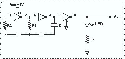
The MC74HC04 IC is a low cost CMOS Hex Inverter. I used this type mainly because, it is what I have, although you can use LS type but, with a little modification or exemptions. (View)
View full Circuit Diagram | Comments | Reading(2553)
LED VU Meter with LM3914N
Published:2012/9/16 21:26:00 Author:Ecco | Keyword: LED, VU Meter
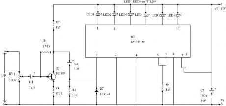
The circuit is based on an LM3914N bar graph display driver device (IC1), which can be used to drive up to ten LEDs. This is connected so that with OV12 at the input only the first LED indicator switches on. This simple peak reading VU meter circuit uses six LEDs to indi-cate six signal levels at 14, 8, 3, 0, +3, and +6dB, or any other levels having the same spacing (e.g. 17, 11, 6, 3, 0, and +3dB, if preferred). About 24mV peak to peak is needed in order to activate the highest LED indicator, so the circuit is sufficiently sensi-tive to be used with any normal item of audio equipment. (View)
View full Circuit Diagram | Comments | Reading(4126)
VU Meter with Audio Mixer circuit
Published:2012/9/16 21:25:00 Author:Ecco | Keyword: VU Meter , Audio Mixer
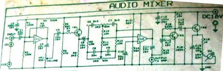
This is audio mixer circuit. The circuit is for one channel input, if you need, for example 5 channel mixer, then you need to build 5 similar circuits. (View)
View full Circuit Diagram | Comments | Reading(4459)
VU meter with LM3915
Published:2012/9/16 21:24:00 Author:Ecco | Keyword: VU meter
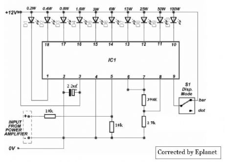
This nifty sound level meter is a perfect one chip replacement for the standard analog meters. It is completely solid state and will never wear out. The whole circuit is based on the LM3915 audio level IC and uses only a few external components. (View)
View full Circuit Diagram | Comments | Reading(5499)
Thermometer circuit with AD595
Published:2012/9/16 21:24:00 Author:Ecco | Keyword: Thermometer circuit
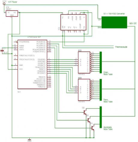
the entire circuit is comprised of integrated circuits. This makes for some easy organization when it goes to the circuit board for soldering. In addition, I used only 3 of the pins on the 3rd nixie tube for the hundreds position in the display. Since I was only using three, I decided to save a 74141 IC and just use a few high voltage transistors (MPSA42). I figure the thermometer will very unlikely be in any situation where a temperature between 0 and 399 will ever need to be displayed, and if it is, the electronics will probably not work anyways. (View)
View full Circuit Diagram | Comments | Reading(2487)
Digital Thermometer circuit up to 150°C
Published:2012/9/16 21:23:00 Author:Ecco | Keyword: Digital Thermometer, 150°C
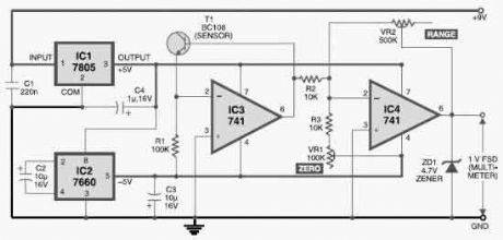
This digital thermometer circuit can measure temperatures up to 150°C with an accuracy of ±1°C. The temperature is read on a 1V full scale-deflection (FSD) moving-coil voltmeter or digital voltmeter. Operational amplifier IC 741 (IC3) provides a constant flow of current through the base-emitter junction of npn transistor BC108 (T1). The voltage across the base-emitter junction of the transistor is proportional to its temperature. (View)
View full Circuit Diagram | Comments | Reading(1482)
Heat Sensor Circuit using LM741
Published:2012/9/16 21:23:00 Author:Ecco | Keyword: Heat Sensor
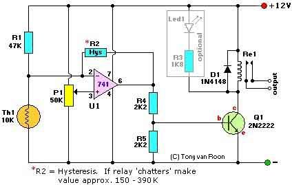
The following page outlines detail information on how to step by step design a Simple Heat Sensor Circuit. This circuit design utilized LM741 as the operational amplifier. (View)
View full Circuit Diagram | Comments | Reading(5981)
Very simple Delay circuit
Published:2012/9/16 21:21:00 Author:Ecco | Keyword: simple Delay
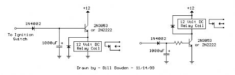
The two circuits di atas illustrate opening a relay contact a short time after the ignition or ligh switch is turned off. The capacitor is charged and the relay is closed when the voltage at the diode anode rises to 12 volts. The circuit on the left is a common collector or emitter follower and has the advantage of one less part since a resistor is not needed in series with the transistor base. However the voltage across the relay coil will be two diode drops less than the supply voltage, or about 11 volts for a 12.5 volt input. (View)
View full Circuit Diagram | Comments | Reading(1262)
Car Exhaust Meter
Published:2012/9/16 21:20:00 Author:Ecco | Keyword: Car Exhaust Meter
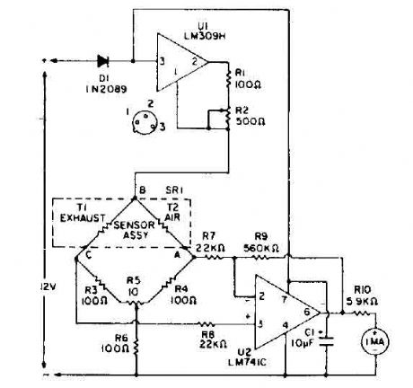
Bridge circuit contains two resistors lOO-ohm (R3 and R4), and two thermistors (Tl and T2). At room temperature, the resistance of T1 and 1'2 is about 2000 ohms. When they are each heated to 150 ° C by an RNA 10 current, the resistance value decreases to 100 ohms. So. the four elements include a bridge circuit. CO is a characteristic that conducts heat from a thermistor at a rate different from that of air. A thermistor, TI, is exposed to automobile exhaust, while the other, 1'2, is isolated in an environment of clean air. Unlike thermal conduction bridge imbalance. A voltage difference is caused between points A and C. A differential amplifier. VI, amplifies this difference and leads to the counter with a current sufficient to read the percentage of CO and air-fuel ratio. A control panel before the balance, R5, balances the bridge and calibrates the instrument. The calibration is performed when both thermistors are exposed to outside air. (View)
View full Circuit Diagram | Comments | Reading(0)
AVR Microcontroller Digital Clock with ATtiny2313
Published:2012/9/16 21:19:00 Author:Ecco | Keyword: AVR Microcontroller , Digital Clock
Usually we see Digital clock on LCD or 7 segmen. But, this AVR Digital Clock which is designed by Ficara Emilio displayed on Oscilloscope. The project use ATtiny 2313 as the main controller. What an interesting microcontroller project. Source code and schematic available for download. (View)
View full Circuit Diagram | Comments | Reading(2455)
Digital Clock circuit with CMOS 4047
Published:2012/9/16 21:18:00 Author:Ecco | Keyword: Digital Clock, CMOS
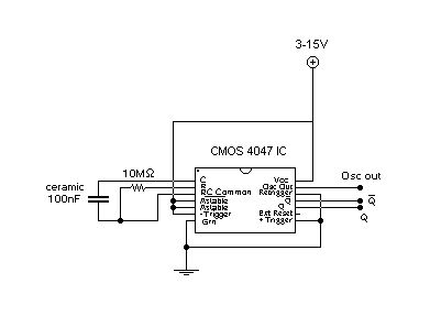
This circuit provides a digital square wave that can be viewed directly or used to drive other circuits. It used the CMOS 4047 Low-Power Monostable/Astable Multivibrator. As used in Tom Duncan's Adventures with Digital Electronic's Book, to drive CMOS Decade of 4-bit binary counters. (View)
View full Circuit Diagram | Comments | Reading(1651)
Clock circuit using SX 28 internal oscillator
Published:2012/9/16 21:18:00 Author:Ecco | Keyword: Clock circuit, internal oscillator
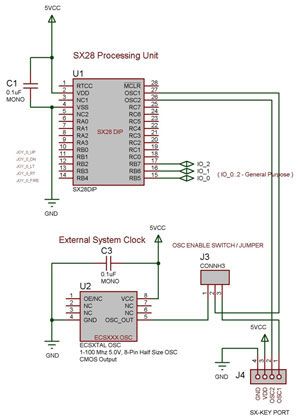
The SX 28 internal oscillator Is not that fast so an external oscillator can be hooked up to the processor as shown in the diagram to increase the operation cycles per second. (View)
View full Circuit Diagram | Comments | Reading(1212)
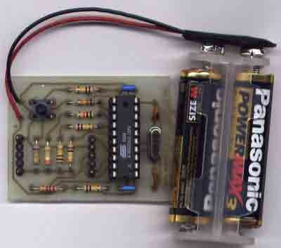
Digital Up-Down Counter with CD40110BE
Published:2012/9/16 20:52:00 Author:Ecco | Keyword: Digital Up-Down Counter
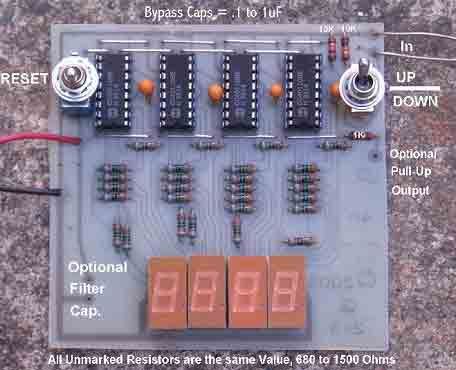
This circuit board design uses a CD40110BE, and Up/Down Counter ICs. The CD40110BE is a dual-clocked up/down counter with a special preconditioning circuit that allows the counter to be clocked, via posting going inputs, up or down regardless of the state or timing of the other clock line. (View)
View full Circuit Diagram | Comments | Reading(5061)
digital voltmeter with LED display (ICL7107)
Published:2012/9/16 20:51:00 Author:Ecco | Keyword: digital voltmeter , LED display
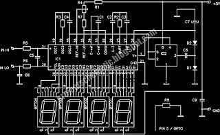
This is a design circuit for digital voltmeter with LED display. Itas ideal to use for measuring the output voltage of your DC power supply. It includes a 3.5-digit LED display with a negative voltage indicator. It measures DC voltages from 0 to 199.9V with a resolution of 0.1V. The voltmeter is based on single ICL7107 chip and may be fitted on a small 3cm x 7cm printed circuit board. The circuit should be supplied with a 5V voltage supply and consumes only around 25mA. (View)
View full Circuit Diagram | Comments | Reading(4597)
12V Analogue Battery Volt Meter
Published:2012/9/16 20:50:00 Author:Ecco | Keyword: 12V , Analogue Battery , Volt Meter
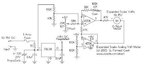
This circuit is used to measure the voltage on a 12V (nominal) lead acid rechargeable battery system. It was specifically designed for use in solar powered systems, but is general enough that it can be used for automotive or other 12V systems. Lead acid batteries normally spend their working lifetime in the voltage range of 11-15 Volts. This meter circuit was designed to show the voltage range of 10-15V on an analog meter movement, it can be used to show the battery charge state from empty to full. (View)
View full Circuit Diagram | Comments | Reading(1880)
Water Softener Circuit
Published:2012/9/16 20:50:00 Author:Ecco | Keyword: Water Softener
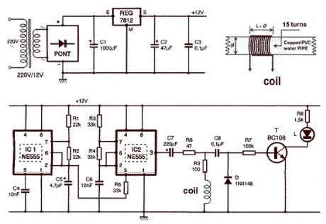
That circuit is based at a technique to remove or neutralize the salt in water, and protect the pipes at home as well as the washing machines or our selves from salt. Its called water softener and its automated circuit using two 555 timers. (View)
View full Circuit Diagram | Comments | Reading(0)
Delay circuit with NE555 timer
Published:2012/9/16 20:48:00 Author:Ecco | Keyword: Delay , timer
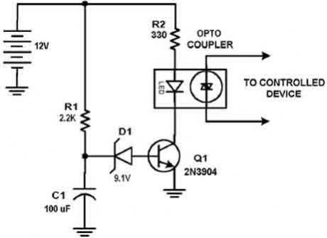
This circuit design was used to switch on device via a LED photocell arrangement (optocoupler) using components R1, C1, D1 and Q1. It produces a delay on powering up to ensure correct sequencing of certain equipment. A very simple delay timer using a single transistor and an R-C timing circuit.
(View)
View full Circuit Diagram | Comments | Reading(0)
The simplest Electronic Door Lock
Published:2012/9/16 20:37:00 Author:Ecco | Keyword: simplest , Electronic Door Lock
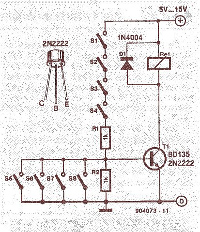
To put the relay in tension the 4 buttons S1 S4 must be pressed. If anyone of the 4 butoons S5 S8 are pushed the relay donts tension ( dont receives supply voltage ). The supply voltage must be equal to the working voltage of the relay. One transistor like BD135 can commute up to 0.5A, in the same tine 2N2222 can do only 0.2A.
(View)
View full Circuit Diagram | Comments | Reading(1514)
Wireless Keylogger circuit
Published:2012/9/16 20:37:00 Author:Ecco | Keyword: Wireless Keylogger
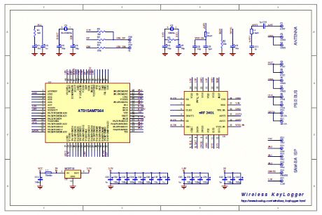
The Wireless Keylogger consists of two main building blocks: the transmitter, and the receiver. The actual keylogging takes place in the transmitter, which is in fact a PS/2 hardware keylogger, with a built-in 2.4 GHz wireless module. Captured keystroke data is transmitted through the radio-link in real-time, rather than getting stored. The receiver on the other hand, is a wireless acquisition unit with a USB interface. All keystroke data received from the transmitter is sent to the host computer via USB. From the software side, this data is available through a virtual COM port, allowing any terminal client to be used for visualizing keystroke data. (View)
View full Circuit Diagram | Comments | Reading(0)
Anti-bag-snatching alarm circuit
Published:2012/9/16 20:34:00 Author:Ecco | Keyword: Anti-bag-snatching, alarm
This circuit, enclosed in a small plastic box, can be placed into a bag or handbag. A small magnet is placed close to the reed switch and connected to the hand or the clothes of the person carrying the bag by means of a tiny cord. If the bag is snatched abruptly, the magnet looses its contact with the reed switch, SW1 opens, the circuit starts oscillating and the loudspeaker emits a loud alarm sound. (View)
View full Circuit Diagram | Comments | Reading(1180)
| Pages:333/2234 At 20321322323324325326327328329330331332333334335336337338339340Under 20 |
Circuit Categories
power supply circuit
Amplifier Circuit
Basic Circuit
LED and Light Circuit
Sensor Circuit
Signal Processing
Electrical Equipment Circuit
Control Circuit
Remote Control Circuit
A/D-D/A Converter Circuit
Audio Circuit
Measuring and Test Circuit
Communication Circuit
Computer-Related Circuit
555 Circuit
Automotive Circuit
Repairing Circuit