
Circuit Diagram
Index 320
Overflow Indicator circuit
Published:2012/9/25 1:03:00 Author:muriel | Keyword: Overflow Indicator
This Simple circuit can monitor overflow of water from the Overhead tank. The sensor placed close to the lid of the overhead tank always monitor the presence of water coming through the lid and gives a music tone when it senses the over flow. ROM IC UM66 is used to generate melody tone.The circuit is easy to construct. Sensor can be a small piece of common PCB with line tracks. Points A and B are connected to two adjacent tracks using thin plastic wire. Normally T1 is not conducting and no current flows through it. This keeps T2 also non conducting. When water falls on the sensor, electrical conductivity occurs between points A and B though water. This gives base bias to T1 and it conducts to charge C1. When the voltage level in C1 increases, T2 gets base bias and conducts. It gives power to the melody generator IC UM66. Since UM 66 requires 3 volts, Zener diode ZD is used to regulate the supply of UM 66 to 3 volts. Output pulses from UM 66 are amplified by T3 and the Speaker gives Music tone. The music tone continues till the overflow water ceases.
Overflow Indicator Circuit
The unit can be placed in the room for easy monitoring. Fix the sensor close to the lid of the overhead tank. Connect the sensor with the points A and B using long plastic wire. Since the copper tracts in the sensor may corrode due to weathering, periodic cleaning or replacement is necessary. To avoid this two brass pins or screws can be used. But these should be arranged closely with minimum spacing of 2mm between them. Then only current passes through water and the brass pins. (View)
View full Circuit Diagram | Comments | Reading(890)
Solar Power System Guard
Published:2012/9/25 1:01:00 Author:muriel | Keyword: Solar Power,System,Guard
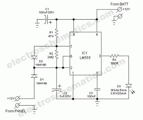
The common home solar power system, in principle consists of a roof-mounted solar panel, a charge controller and a storage battery bank plus direct or electronic inverter powered electric lighting units. In some situations, the solar panel is mounted on a mast extended from ground and this may become an obstacle during night time.Here, ultra simple circuit of an obstacle indicator is presented. Just assemble the circuit on a piece of general-purpose circuit board and then enclose it in small ABS box. Next, attach the unit on the solar panel mast using suitable clamps. This little circuit takes power from the 12V battery of the solar system and switch on a blinking white light spot, when dc power supply from the solar panel is absent, ie at night time!The solar power system guard circuit is a gated astable multivibrator wired around the”evergreen” tiny timer chip LM555(IC1). The thing that makes this design special is the ultra-low current consumption. The white clear glass type LED (D3) flashes only very briefly each time with a duty cycle near 10%. The circuit is gated through diode D1 such that the flashing only begins when sufficient supply from the solar panel is absent.
Solar Power Illumination System Circuit
(View)
View full Circuit Diagram | Comments | Reading(2281)
LED Chaser circuits
Published:2012/9/25 1:00:00 Author:muriel | Keyword: LED, Chaser
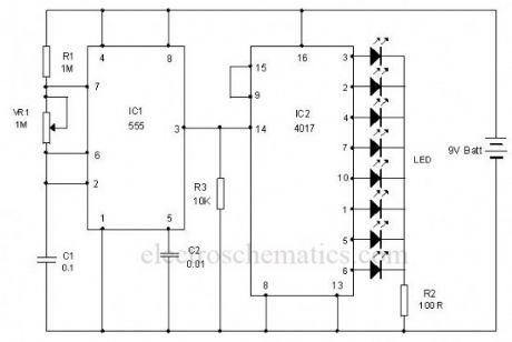
This is the circuit of a simple LED chaser. The LEDs lights one by one for a period of 1second and the cycle repeats giving the running light appearance. The circuit uses two ICs (one is 555) to drive the LEDs.IC1 (NE555) is the popular timer IC wired in the Astable Multivibrator mode. Resistors R1, VR1 and capacitor C1 act as the timing components and the output pulses are available from the output pin 3 of IC1. These pulses are given to the input pin 14 of the Johnson decade counter IC CD4017. Out of the 10 outputs of IC2, eight outputs are used to drive the LEDs. The ninth output pin 9 is connected to the reset pin 15 to stop the counting. So that the cycle repeats. With the value of C1, each LED remains on for 1second. When one LED turns off, the second on turns on. This cycle repeats giving the running light appearance. Resistor R3 keeps the input pin 14 of IC2 low after each pulse.VR1 adjusts the speed of LED chasing.
LED Chaser Circuit
(View)
View full Circuit Diagram | Comments | Reading(2769)
LED Chaser circuit
Published:2012/9/25 1:00:00 Author:muriel | Keyword: LED,Chaser

This is the circuit of a simple LED chaser. The LEDs lights one by one for a period of 1second and the cycle repeats giving the running light appearance. The circuit uses two ICs (one is 555) to drive the LEDs.IC1 (NE555) is the popular timer IC wired in the Astable Multivibrator mode. Resistors R1, VR1 and capacitor C1 act as the timing components and the output pulses are available from the output pin 3 of IC1. These pulses are given to the input pin 14 of the Johnson decade counter IC CD4017. Out of the 10 outputs of IC2, eight outputs are used to drive the LEDs. The ninth output pin 9 is connected to the reset pin 15 to stop the counting. So that the cycle repeats. With the value of C1, each LED remains on for 1second. When one LED turns off, the second on turns on. This cycle repeats giving the running light appearance. Resistor R3 keeps the input pin 14 of IC2 low after each pulse.VR1 adjusts the speed of LED chasing.
LED Chaser Circuit
(View)
View full Circuit Diagram | Comments | Reading(2702)
IC 555 Design Note
Published:2012/9/25 0:59:00 Author:muriel | Keyword: 555,Timer IC
The popular Timer IC 555 is extensively used in short duration timing applications. IC 555 is a highly stable integrated circuit functioning as an accurate time delay generator and free running multivibrator. But one of the serious problem in 555 timer design is the false triggering of the circuit at power on or when voltage changes. The article describes how IC555 is designed perfectly to avoid false triggering.
Functional aspects of pins
Trigger Pin 2
Usually pin2 of the IC is held high by a pull up resistor connected to Vcc. When a negative going pulse is applied to pin 2, the potential at pin 2 falls below 1/3 Vcc and the flip-flop switches on. This starts the timing cycle using the resistor and capacitor connected to pins 6 and 7.
Reset pin 4
Reset pin 4 can be controlled to reset the timing cycle. If pin 4 is grounded, IC will not be triggered. When pin4 becomes positive, IC becomes ready to start the timing cycle. Reset voltage is typically 0.7 volts and reset current 0.1 mA. In timer applications, reset pin should be connected to Vcc to get more than 0.7 volts.
Control Voltage pin 5
Pin5 can be used to control the working of IC by providing a DC voltage at pin5. This permits the control of the timing cycle manually or electronically. In monostable operation, the control pin5 is connected to ground through a 0.01 uF capacitor. This prevents the timing interval from being affected by AC or RF interference. In the Astable mode, by applying a variable DC voltage at pin 5 can change the output pulses to FM or PWM.
Threshold pin 6 and Discharge pin 7
These two inputs are used to connect the timing components- Resistor and Capacitor. The threshold comparator inside the IC is referenced at 2/3 Vcc and the trigger comparator is referenced at 1/3 Vcc. These two comparators control the internal Flip-Flop of the circuit to give High or Low output at pin 3.When a negative going pulse is applied to pin 2, the potential at pin2 drops below 1/3 Vcc and the trigger comparator switches on the Flip-Flop. This turns the output high. The timing comparator then charges through the timing resistor and the voltage in the timing capacitor increases to 2/3 Vcc.( The time delay depends on the value of the resistor and capacitor. That is, higher values, higher time).When the voltage level in the capacitor increases above 2/3 Vcc, the threshold comparator resets the Flip-Flop and the output turns low. Capacitor then discharges through pin 7.Once triggered, the IC will not responds to further triggering until the timing cycle is completed.
The time delay period is calculated using the formula T= 1.1 Ct Rt. Where Ct is the value of Capacitor in PF and Rt is the value of Resistor in Ohms. Time is in Seconds.
How to eliminate false triggering?
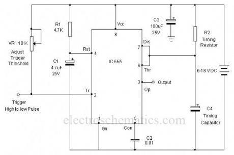
The circuit diagram shown below is the simple monostable using IC 555. To eliminate the false triggering resistor R1 and Capacitor C1 are connected to the reset pin 4 of the IC. So the reset pin is always high even if the supply voltage changes. Moreover capacitor C3 connected close to the Vcc pin 8 acts as a buffer to maintain stable supply voltage to pin 8. Using this design, it is easy to avoid false triggering to a certain extent.
555 Monostable circuit
(View)
View full Circuit Diagram | Comments | Reading(2298)
Telephone Tapping Indicator
Published:2012/9/25 0:58:00 Author:muriel | Keyword: Telephone,Tapping, Indicator
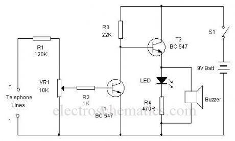
This simple circuit can indicate a misuse or tapping of Telephone line through a loud alarm. The circuit is too simple and can be easily assembled on a common PCB.Line voltage of Telephone lines is around 48 volts DC in the On hook state. When the handset is lifted, this voltage reduces to 12 volt DC. This change in voltage level is used to activate the circuit. When the switch S1 is closed, circuit becomes active and the telephone enters into the armed state. The high volt DC from the telephone line passes through R1 and VR1 and bias T1 into conduction. As a result, the collector of T1 goes to ground potential to inhibit T2 from conduction. Buzzer and LED thus remain off.When the handset is lifted, the DC voltage from the telephone lines drops to 12 volts. This turns off T1 and T2 conducts. Buzzer beeps and LED lights indicating that the telephone is using.
Telephone Tapping Indicator Circuit
(View)
View full Circuit Diagram | Comments | Reading(909)
Door ajar alarm circuit
Published:2012/9/25 0:58:00 Author:muriel | Keyword: Door,ajar,alarm circuit
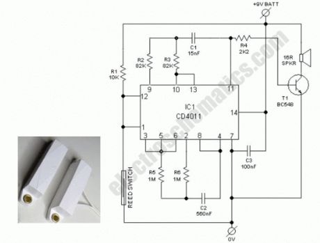
Ever accidentally left your front door ajar and had a pet escape? Here is a smart solution to this problem. The circuit is fairly simple but a great example of using a tiny circuit to get the job done. All you need is a CD4011 IC plus a handful of components. In this door ajar alarm/beeper circuit, a bar magnet-reed switch combination is used as the door sensor. When the door is closed, as per mechanical arrangement, the bar magnet near the reed switch close its switch contacts. Now the beeper circuit built around CD4011 (IC1) is disabled by the logic low state at its input terminals (pins 1&12).When door is opened the beeper is enabled by the logic high state and the speaker starts beeping intermittently at a rate of about 0.5 secs on/0.5 secs off. Frequeny of this gated aural output is near 450 Hz. After assembling, enclose the circuit including the reed switch, in a plastic enclosure and mount it on the door frame.Next fit the bar magnet in the door exactly in alignment with the reed switch so that when door is closed the bar magnet is at the close vicinity of the reed switch. For powering the circuit, use an alkaline type 9V compact battery.
Door ajar beeper/alarm circuit schematic
(View)
View full Circuit Diagram | Comments | Reading(1321)
Light Controlled Bistable circuit
Published:2012/9/25 0:57:00 Author:muriel | Keyword: Bistable,Controlled,Light

This circuit can control AC loads such as Lights, Fans etc through the remote handset of TV. The circuit uses the popular timer IC 555 in the Bistable mode.In the Bistable mode output IC555 keeps two states, either low or high. When a negative pulse is applied to the trigger pin 2 of 555, the output turns high and remains as such in the latched state. If a positive pulse is applied to the Threshold pin 6, its output turns low and remains as such. This property is used to control the AC load.
Light Controlled Bistable Schematics
The negative and positive pulses are given to the trigger and threshold pins of 555 through the light activated phototransistors T1 and T2. The collector of T2 is connected to the trigger pin 2 through diode D1. Similarly the emitter of T2 is connected to the threshold pin 6 through diode D2. When the IR beam of remote is focused momentarily to T2, it conducts and takes the trigger pin 2 to ground potential. This triggers IC1 and its output goes high. T3 then conducts and relay turns on. Load connected to the NO contacts of the relay gets electrical continuity and turns on. When the IR beam is focused on T1, Current passes from its emitter into the threshold pin6 and the output of IC1 turns low and the relay de-energize to switch off the load.
Setting: Keep both Photo transistors in Black tubes to avoid ambient light falling on them. This is necessary for the proper functioning of the circuit. Since the remote emits pulsating IR beam, use only the On/Off button to give continuous IR beam. Press the button only once to activate the circuit. Keep the photo transistors facing two directions so that IR rays will not interfere them. The circuit can also be activated through torch and Laser pointer. Adjust VR1 and VR2 to set the sensitivity of Phototransistors at the particular light level in the room. That is, the circuit should not be activated in day light. (View)
View full Circuit Diagram | Comments | Reading(1787)
LED workbench lighting
Published:2012/9/25 0:54:00 Author:muriel | Keyword: LED,workbench,lighting

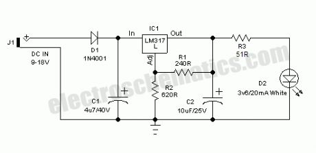
Here is a very useful workbench lighting unit for electronics hobbyists. The portable inspection lamp circuit consists of an on-board voltage regulator and a high-bright 5mm white LED. Any 9 to 18 volt dc rated ac mains adaptor, capable to source about 100 mA of output current can be used to power this portable inspection lamp.After contruction the led workbench light circuit should be enclosed in a suitable plastic bottle cap as illustrated here. The miniature lens shown is an optional component. In the prototype, plastic made lens lifted from a discarded torch was used!The adjustable 3-pin voltage regulator IC1 (LM317L) in TO-92 pack, is here tuned to supply an output of near 4.5 volt dc. This supply is directly fed to the white LED (D2) through the current limiter resistor R3 (51 Ohm). Diode D1 (1N4001) works as an input polarity protection guard and two small electrolytic capacitors (C1 and C2) connected at the input and output pins of IC1 improves the overall stability of the regulator circuit. Use a standard RCA or EP socket as the input terminal J1.
LED workbench lighting lamp circuit schematic
(View)
View full Circuit Diagram | Comments | Reading(2022)
Automatic emergency light circuits
Published:2012/9/25 0:54:00 Author:muriel | Keyword: Automatic,emergency light
This low cost automatic emergency lighting circuit turns on a lamp during power failures. It is powered by a NiCad battery that is being charged by the main power line when there is no blackout. The circuit design is very simple and can be made by almost anyone. How does the automatic emergency light works
The voltage from the step down transformer is rectified by diode D1 and filtered by C1. The NiCad battery gets charged with about 100 mA via the diode D2 and resistor R1. The battery must have a capacity of at least 2 Ah to tolerate the charging rate.
When the main power supply fails during a blackout, the charging current is interrupted and a current flows from the base of T1 via resistor R2 which triggers the transistor to conduct and the two emergency lamps light up. When the main power returns, the charging current flows again through D2 and the transistor turns the lamps off.
The “TEST” button S1 is used to check the function of the circuit. If the secondary coil of the transformer delivers a higher voltage level, replace R1 with a higher value resistor to avoid exceeding the maximum charging current allowed for the NiCad battery being used.
Emergency light parts220V to 4.5V / 2A TransformerD1 = 1N4004D2 = 1N4001R1 = 33Ω/1WR2 = 470ΩC1 = 470µF/16VT1 = 2SB242La1, La2 = 2.5V bulbsBattery = 2.5V / 2Ah Nicad
Automatic Emergency Lighting Circuit Diagram
(View)
View full Circuit Diagram | Comments | Reading(2097)
Jumbo Flashing LED Lights
Published:2012/9/25 0:52:00 Author:muriel | Keyword: Flashing,LED Lights
This is a flashing led lights circuit powered from a 12V DC power supply that uses the well known 555 IC. Flashing lights have many and varied applications in life. They are used as warning lights on highways to increase road safety, as beacons on towers, as advertising signs on shop windows,and so on.
Mechanically operated flashers have a short life and many of them generate lot of electrical interference by sparking at the switch contacts. On the other hand, neon lights are power hungry types.
How does the flashing led lights works
12VDC powered true solid-state circuit of the Jumbo LED flasher presented here is wired around LM555(IC1). This IC workes as a low frequency oscillator, drives 5 to 10mm sized, 4 to 40 Red LEDs through a medium power npn transistor 2N2222 (T1).
LM555 IC is configured in a different style by adding a potential divider at its control terminal (Pin 5) to shift the comparator reference levels either higher or lower than the nominal 1/3, 2/3 levels. User can change the LED flashing rate by adjusting the P1.
LED Flashing Lights Circuit Schematic
(View)
View full Circuit Diagram | Comments | Reading(2874)
PC Power Box with E-fuse
Published:2012/9/25 0:52:00 Author:muriel | Keyword: PC,Power Box

This little circuit will help you to remove all surplus small ac mains adaptors from your desktop. The circuit is nothing, but a smart dc power box directly powered by the smps of your desktop personal computer. Regulated, clean and protected +12VDC is available at the output of this unit. In addition, a USB power port is provided to re-charge portable devices including cellphones and music players, etc.How does the pc power box worksAll you need is to open your system box and connect an unused 4-pin drive power connector from the system smps to this circuit. +12V (Yellow wire) from the smps is processed by a resettable electronic fuse built around components T1, T2 and T3 and feed to the output terminal. Similarly the +12V is down converted to stable +5V by fixed 3 pin regulator IC1.As a result, +12V (500 -750mA max, based on the electrical characteristics of T2 used) and +5V (1A max) DC supplies are available for external use, without affecting the normal pc functions. Switch S1 is the power on/off cum reset switch. Resistor R3 sets the maximum allowable output current rate and T1 disables the output power switch T3, when output load current exceeds the set value.
Smart dc power box circuit schematic
(View)
View full Circuit Diagram | Comments | Reading(1510)
Positive Trigger Timer circuit
Published:2012/9/25 0:52:00 Author:muriel | Keyword: Positive,Trigger,Timer
This 555 Timer is designed unusually to give a positive output through a control over its reset pin. Usually the timer IC 555 is triggered by applying a negative going pulse to its trigger pin 2. This timer is triggered through a positive pulse in its reset pin.
In the Monostable mode IC 555 starts timing cycle when a negative pulse is applied to its trigger pin2. The timer starts oscillations only when its trigger pin goes to ground potential. The reset pin 4 is usually connected to positive rail to keep the timer ready to oscillate.
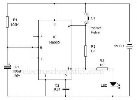
Here an alternate mode of operation is experimented. At power on, the voltage level in the capacitor C1 is less than 1/3 Vcc. This resets the internal Flip-Flop of IC and its output goes high and LED turns on.C1 then charges through R1. When the voltage level in C1 rises to 2/3 Vcc, output of IC turns low and LED turns off. This low output from pin 3 pulls the reset pin 4 to a low state and IC latches to off condition. The latching state continues even if the capacitor C1 discharges through the discharge pin 7 and voltage in C1 drops below 1/3 Vcc.
Positive Trigger Timer circuit
(View)
View full Circuit Diagram | Comments | Reading(3666)
LED Scanner circuit
Published:2012/9/25 0:50:00 Author:muriel | Keyword: LED,Scanner
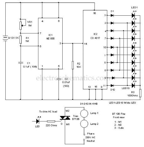
Here is a simple LED chaser simulating a scanner through the back and forth light effect. It used high bright White LEDs to give the chaser effect. The circuit uses an oscillator to produce fast pulses and a decade counter to drive the LEDs.IC1 is designed as an astable multivibrator to give continuous positive pulses to the decade counter. Variable resistor VR1, R1 and C1 form the timing components. By adjusting VR1, it is possible to change the speed of the scanning LEDs.
Output pulses from IC1 are fed to the clock input of the decade counter IC2. Resistor R2 keeps the clock input of IC2 low after each positive to negative transitions of input pulses. This is necessary because sometimes the clock input of the decade counter stays positive and does not accept input pulses.
LED Scanner Circuit
Note: This circuit can be used to drive AC loads like 60 watts bulbs for decoration purpose. For that slight modification is necessary. Connect the cathode of LED to the gate of a Triac (BT136) through a 220 ohms resistor. Connect bulb to the M2 pin of triac in series with the phase line as shown in the diagram. Six 60 watts bulbs can be connected serially to each triac (BT136 is rated to 400 watts). (View)
View full Circuit Diagram | Comments | Reading(2199)
Invisible Infrared Alarm Circuit
Published:2012/9/25 0:49:00 Author:muriel | Keyword: Invisible,Infrared,Alarm Circuit
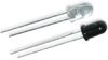
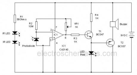
This circuit uses Invisible Infrared light to detect the movement of people through the door. A short beep will be generated when the infrared beam breaks. So it is ideal to monitor the passages in shops, banks etc where many people are moving.
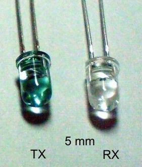
Two Infrared LEDs always emit continuous infrared beam to the Photodiode. The IR LEDs and Photodiode are placed on the opposite frames of the door and properly aligned. Resistor R1 is the current limiter giving around 70 mA current through the LEDs which is necessary to increase the output of IRLEDs.IC1 is designed as Current to Voltage converter with the reverse biased photodiode connected to its inverting input. The non inverting input is directly grounded.
Resistor R2 and VR1 forms the feedback loop to adjust the sensitivity of the IC. Normally the Photodiode generates a small current by accepting the energy from the infrared Beam. This tiny current will be amplified by IC1 and gives a high output. This forward biases T1 and it conducts. The emitter current from T1 keeps T2 off since it is a PNP transistor. Since T2 is off, Buzzer remains silent. In short, in the standby mode, LED glows indicating the active state of circuit and buzzer remains off.
Infrared Invisible Alarm Circuit
When a person crosses the infrared beam, Photodiode turns off and the output of IC1 turns low. T1 then cutoff and T2 forward biases. This activates the buzzer for a short period.
IR LED and Photodiode
Note: Proper alignment of infrared LEDs and Photodiode is necessary. After orienting the IR LEDs to the photodiode, adjust VR1 till Red LED turns on and buzzer stops beeping. This is the standby mode. Mask photodiode with hand. Buzzer should beep. The circuit is ready to use.?
16 Responses to “Invisible Infrared Alarm Circuit”
(View)
View full Circuit Diagram | Comments | Reading(2262)
Humidity Control Switch circuit
Published:2012/9/25 0:47:00 Author:muriel | Keyword: Humidity Control,Switch
This humidity controlled switch circuit turns on and off an electrical load (for example a heater) depending on the moisture content of the surrounding air. The moisture is “sensed” with the help of a plate capacitor C2. This capacitor is similar to the old air dielectric plate capacitors in your vintage AM radio. It uses 2 ICs: LM358 and 4001.How does the humidity controlled switch works
At a certain humidity level, the circuit switches on the load. The moisture level is converted to a voltage through R3 in the first part of the circuit.The first opamp A1 functions as a high impedance. The second opamp A2 functions as a comparator with a hysteresis of about 15%.
The variable scale of the potentiometer P1 produces voltages from 0.6V to 3 volts and proportional to moisture levels from 20 to 100%. The P1 therefore sets the moisture level where the circuit activates. Once the moisture level reaches above the set level, the triac TR1 triggers and the attached load (heater) turns on.
The current consumption of the circuit is around 13 mA while activated. If you use it to control a heater, you can plug in two 100 watt bulbs. If you use light bulbs as heating element, enclose them in a metal container.
Moisture Controlled Switch Circuit Schematic
(View)
View full Circuit Diagram | Comments | Reading(1282)
12 Volt Dual Power Supply circuit
Published:2012/9/25 0:46:00 Author:muriel | Keyword: 12 Volt,Dual,Power Supply

Here is the standard dual power supply using the Positive and Negative Voltage regulator ICs. It can give +12 volt and – 12 volt DC with a common ground.This power supply is ideal to power amplifier circuits that require well regulated dual power supply. It can give 1 ampere current to the circuit.14-0-14 volt 1 Ampere step down transformer is used to drop 230 volt AC to 14 volt DC which is then rectified using the standard full wave bridge rectifier comprising D1 through D4.Smoothing capacitors C1 and C2 remove the ripples from low volt AC.Two regulator ICs are used to generate + 12 volt and – 12 volt DC. IC1 is 7812 positive regulator giving +12 volt regulated output .
12 Volt Dual Power Supply Circuit
(View)
View full Circuit Diagram | Comments | Reading(3992)
Remote Controlled Alarm circuit
Published:2012/9/24 22:28:00 Author:muriel | Keyword: Remote,Controlled,Alarm
A very interesting remote controlled alarm circuit using TSOP1736. Routing of an electric cable to attach a calling bell switch near the bed of an old age/patient is not a good idea. Here is an ultra simple battery operated remote controlled alarm to help old age members/patients in bed, especially at home/hospital. Any tv/video infrared remote control handset (36Khz) can be used to arm the alarm!How does the remote controlled sound alarm worksAt the heart of the circuit is the popular integrated infrared sensor TSOP1736.The TSOP1736 is a miniaturized receiver for infrared remote control systems. PIN diode and preamplifier are assembled on lead frame, the epoxy package is designed as an infrared filter. Further, a bandpassfilter, an integrator stage and an automatic gain control are used to suppress unwanted noise disturbances.When a person needs immediate attention of someone, he should firmly press and hold any button in the keyapad of the remote control handset and aim the handset towards the sensor (IRRX) of the alarm circuit. Instantly, the active piezo-buzzer stars beeping in tune with the modulated infrared signals emitted by the handset. Sametime, a good visual alert is provided by the red colored 10mm LED(D2).
After construction, enclose the whole remote controlled siren unit in a transparent cabinet with the Infrared sensor at the front side of the box. Now power the circuit through a suitable 9V compact alkaline battery. Insertion of an ordinary on/off toggle switch in the positive rail is a good idea. After successful testing, mount the unit in a proper point at the wall of the room/hall, as per the requirement. Finally, the lab prototype is connected to a multidirectional 5V dc buzzer. However, you can use an ordinary 5V dc buzzer or any kind of 5V active piezo-sounder.
Remote Controlled Audio Alarm Circuit Schematic
(View)
View full Circuit Diagram | Comments | Reading(737)
Regulated Charger circuit
Published:2012/9/24 22:27:00 Author:muriel | Keyword: Regulated,Charger
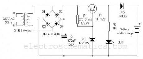
Most of the battery chargers do not have current and voltage regulation provisions. The step down voltage is simply used for charging. These chargers develop internal resistance so the output voltage drops when the battery is connected to the charger. Moreover, fluctuations in the AC line also affect the charging process. This current and voltage regulated charger eliminates these drawbacks and can provide well regulated 12 volt DC for charging.
0-15 1 Ampere step down transformer drops 230 volt AC into 15 volt AC which is rectified through the bridge rectifier comprising D1 through D4. The rectified DC is then made ripple free by C1 and send to the collector of the medium power NPN transistor T1 to give regulated output. Resistor R1 and Zener diode ZD are used for both voltage and current regulation. Output current from the emitter of T1 depends on the value of R1 which can be changed according to the requirement using the ohms law. 12 volt Zener diode gives constant 12 volts to the base of T1 so that output voltage remains 12 volt irrespective of the input fluctuations. Diode D5 is polarity protector that prevents short circuiting if the polarity of the battery is reversed. LED indicates the charging process.
Regulated Charger Circuit
(View)
View full Circuit Diagram | Comments | Reading(1550)
Temperature Alarm circuits
Published:2012/9/24 22:27:00 Author:muriel | Keyword: Temperature Alarm
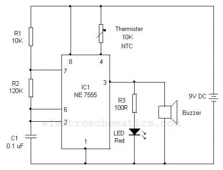
This simple Over heat alarm is to monitor heat generating devices such as motor, inverter etc. The alarm will beep and LED blinks when the temperature of the device increases abnormally.The circuit is a simple Astable multivibrator using the low power CMOS timer IC 7555 which is the low power version of the popular 555 IC. The reset pin 4 of IC1 is used to activate the alarm. The astable will work only if the reset pin 4 becomes high. The reset pin is connected to the positive rail through the 10 K NTC thermister. The NTC (Negative Temperature Coefficient) thermister offers high resistance in cold and its resistance becomes low to few ohms when the temperature in its vicinity increases. So when the temperature is low (as adjusted by the position of the thermister near the device) reset pin of IC1 remains low and astable is in off position and buzzer remains silent. When the temperature near the thermister increases, its resistance decreases and provides voltage to the reset pin of IC1 and the astable starts working.
Temperature alarm circuit
(View)
View full Circuit Diagram | Comments | Reading(2522)
| Pages:320/2234 At 20301302303304305306307308309310311312313314315316317318319320Under 20 |
Circuit Categories
power supply circuit
Amplifier Circuit
Basic Circuit
LED and Light Circuit
Sensor Circuit
Signal Processing
Electrical Equipment Circuit
Control Circuit
Remote Control Circuit
A/D-D/A Converter Circuit
Audio Circuit
Measuring and Test Circuit
Communication Circuit
Computer-Related Circuit
555 Circuit
Automotive Circuit
Repairing Circuit