
Circuit Diagram
Index 304
10W Mini Audio Amplifier Circuit
Published:2012/10/12 22:26:00 Author:muriel | Keyword: 10W, Mini, Audio Amplifier Circuit
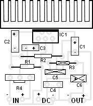
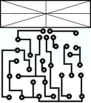
Componets ListR1 : 6 OhmR2 : 220 OhmR3 : nothingR4 : 10 KOhm pontesiometerC1 : 2200 uF / 25VC2 : 470 uF / 16VC3 : 470 nF / 63VC4 : 100 nFC5 : nothingC6 : nothingIC1 : TDA 2003 (View)
View full Circuit Diagram | Comments | Reading(1580)
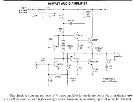
10-W audio amplifier
Published:2012/10/12 22:25:00 Author:muriel | Keyword: 10-W, audio amplifier
View full Circuit Diagram | Comments | Reading(3549)
10-14W Class A amplifier
Published:2012/10/12 22:24:00 Author:muriel | Keyword: 10-14W, Class A amplifier
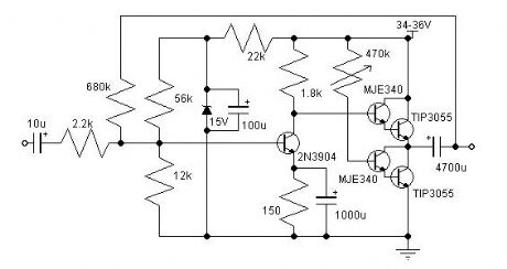
I have built this amplifier and it does sound good. It requires a preamp as it hasn't got much gain. It requires big heat sinks and a large transformer and a great power supply and careful wiring, but in the end it is extremely simple and it sounds very good. The zener diode rejects any ripple coming from the power supply, But you still only want a ripple of 10mV max. The ripple reaching the input is amplified, so the zener gets rid of that, but whatever ripple there is will still reach the power stage. (View)
View full Circuit Diagram | Comments | Reading(1298)
100W Audio Amplifier
Published:2012/10/12 22:22:00 Author:muriel | Keyword: 100W, Audio Amplifier


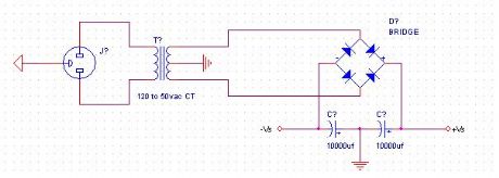
When I was around 17 years old, I acquired electronic habilities during my free time. Music also being one of my hobbies, I decided to use my electronic knowledge to build an audio amplifier. While my amplifier is not the most powerful that exists, it outputs a good quality of sound. It also has succesfully passed the party test . This means it has played as loud as possible without (intolerable) distortion for many hours hours, in a 3-4 ohms load.
Power-supply:I used a 110 volts to 50 volts ac transforer with a center tap. (this means +50 volts and -50volts). Next, I rectify the current with a diode bridge(big enough for 8A), and I filter with 2 big capacitors of 10000uf each.
(View)
View full Circuit Diagram | Comments | Reading(1055)
10 Watt Amplifier Schematic
Published:2012/10/12 22:18:00 Author:muriel | Keyword: 10 Watt, Amplifier
View full Circuit Diagram | Comments | Reading(1336)
1.5w 12v audio amplifier
Published:2012/10/12 22:17:00 Author:muriel | Keyword: 1.5w, 12v, audio amplifier

View full Circuit Diagram | Comments | Reading(3390)
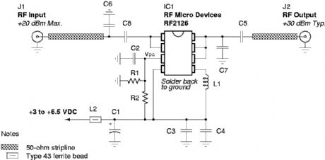
One Watt 2.45 GHz Linear Amplifier
Published:2012/10/12 22:14:00 Author:muriel | Keyword: One Watt, 2.45 GHz , Linear Amplifier

View full Circuit Diagram | Comments | Reading(968)
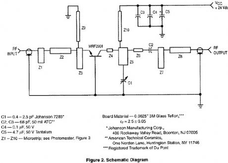
1 Watt 2.3 GHz RF Amplifier Using a MRF2001
Published:2012/10/12 22:13:00 Author:muriel | Keyword: 1 Watt, 2.3 GHz, RF Amplifier
View full Circuit Diagram | Comments | Reading(962)
LM3860,325W Audio Amplifier
Published:2012/10/12 22:11:00 Author:muriel | Keyword: LM3860,325W, Audio Amplifier
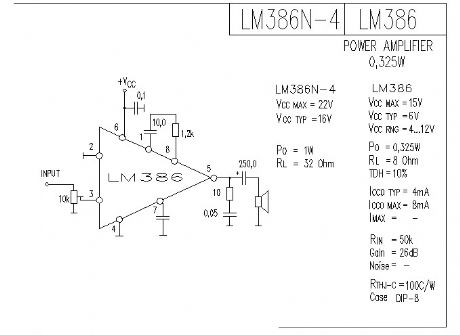
The LM386 is a power amplifier designed for use in low voltage consumer applications. The gain is internally set to 20 to keep external part count low, but the addition of an external resistor and capacitor between pins 1 and 8 will increase the gain to any value from 20 to 200.
The inputs are ground referenced while the output automatically biases to one-half the supply voltage. The quiescent power drain is only 24 milliwatts when operating from a 6 volt supply, making the LM386 ideal for battery operation.
(View)
View full Circuit Diagram | Comments | Reading(1879)
The counter circuit diagram using UGN-3501T Hall sensor
Published:2012/10/12 21:53:00 Author:Ecco | Keyword: counter , Hall sensor
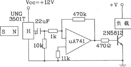
UGN-3501T has a high sensitivity, it can experience a small change in the magnetic field, thus detect the presence or absence of black metal. We use this characteristic for counting. When Ball rolls across the position of the Hall sensor, the sensor outputs a pulse with 20mV peak, and the pulse signal can drive 2N5812 transistor after being amplified by μA741 opamp, so that complete conduction and cutoff process. Then the counter is connected to 2N5812 output end to constitute counters.
(View)
View full Circuit Diagram | Comments | Reading(1966)
The voltage output angle detection circuit using angel sensor signal conditioner UZZ9000 and magnetoresistive sensor KMZ41
Published:2012/10/12 21:46:00 Author:Ecco | Keyword: voltage output , angle detection , angel sensor , signal conditioner , magnetoresistive sensor
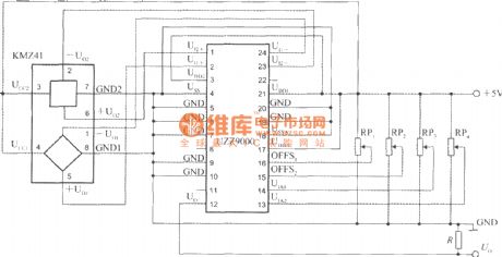
It uses the +5 V power supply, RP1 ~ RP2areoffset voltage adjustment potentiometers, RP3 ~ RP4 aregain adjustment potentiometers. R is the pull-down resistor of output end. The output voltage can be sent to a digital voltmeter to show the measured angle value.
(View)
View full Circuit Diagram | Comments | Reading(2283)
The typical application circuit of capacitive sensor signal conditioner CS2001
Published:2012/10/12 21:43:00 Author:Ecco | Keyword: typical application, capacitive sensor, signal conditioner
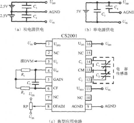
Figure (a) shows the ± 2.5V dual supply wiring diagram, Figure (b) shows a single +5 V power supply wiring diagram. C3, C4 are decoupling capacitors. In the Figure (c), CF is a capacitor for adjusting the bandwidth, RP is a potentiometer for adjusting the gain. CS2001 output voltage is Uo, AGND end leads are followed by digital voltage table ( DVM ).
(View)
View full Circuit Diagram | Comments | Reading(1905)
Temperature measurement circuit with 5-channel low-power programmable sensor signal processor AD7714 and thermocouple
Published:2012/10/12 21:37:00 Author:Ecco | Keyword: Temperature measurement , 5-channel , low-power , programmable sensor, signal processor , thermocouple
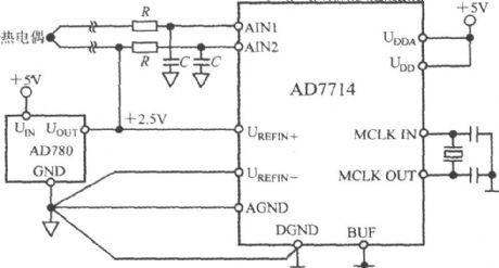
In this application, AD7714 operates in buffered mode, allowing the front terminal to connetc with decoupling capacitor in order to filter the noise on the thermocouple lead. In buffer mode, the AD7714 common mode range is narrow, the differential voltage of thermocouple is in suitable common-mode voltage range, and AD7714's AIN2 input terminal should be biased to +2.5 V reference voltage.
(View)
View full Circuit Diagram | Comments | Reading(1551)
The monostable circuit
Published:2012/10/12 21:54:00 Author:Ecco | Keyword: Monostable
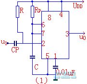
The monostable circuit only has stable state. Under the action of external triggering pulse, the circuit is changed to transient state from the steady state, after transient state maintains for some time, it returns to steady state and generates a rectangular pulse at the output terminal.
(View)
View full Circuit Diagram | Comments | Reading(830)
The typical application circuit of 5 - channel low-power programmable sensor signal processor AD7714
Published:2012/10/11 21:25:00 Author:Ecco | Keyword: typical application , 5 - channel , low-power , programmable sensor, signal processor

The AD7714's UDD, UDDA end can be connected to +3 V or +5 V power supply. The analog input terminal is configured to three differential pair of inputs. AD780 provides precision +2.5 V reference voltage. CS terminal is connected to DGND, AD7714 is configured as a 3-wire serial interface. Master clock provides quartz crystal ( or ceramic resonator ). In some special applications, the UDD and UDDA end are respectively driven by two independent power supply.
(View)
View full Circuit Diagram | Comments | Reading(1057)
The pressure measurement system circuit using 5 - channel low-power programmable sensor signal processor AD7714
Published:2012/10/11 21:38:00 Author:Ecco | Keyword: pressure measurement system , 5 - channel, low-power , programmable sensor, signal processor
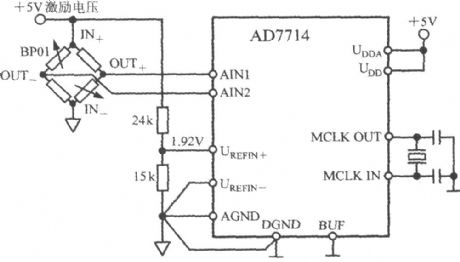
BP01 is a pressure sensor produced by Sensym Company. BP01 is connected as a bridge circuit, OUT + , OUT - ends output differential voltage. When the pressure sensor is applied to nominal full scale pressure ( 40kPa), the sensitivity of differential output voltage is 3mV / V. If it uses +5 V excitation voltage, the sensor full-scale output range is ± 15mV. The excitation voltage is divided by 24kΩ and 15kΩ resistors to provide 1.92 V reference voltage for AD7714, and the excitation voltage fluctuation does not cause a measurement error of the system.
(View)
View full Circuit Diagram | Comments | Reading(1723)
Temperature sensor current transmission circuit
Published:2012/10/11 21:21:00 Author:Ecco | Keyword: Temperature sensor, current transmission
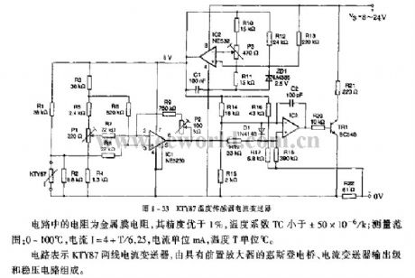
Resistors in the circuit use metal film resistors, and its accuracy is better than 1%, and the temperature coefficient TC is less than ± 50 × 10-6 / k; measuring range: 0 to 100 ° C , the current I = 4 + T/6.25, current unit is mA, and temperature T unit is ℃. The circuit is composed of KTY87 two-wire current transducer, Wheatstone bridge with preamplifier, current transmitter output stage and regulator.
(View)
View full Circuit Diagram | Comments | Reading(2199)
The fourth-order low -pass filter circuit with capacitor element
Published:2012/10/11 21:14:00 Author:Ecco | Keyword: fourth-order, low -pass, filter , capacitor element
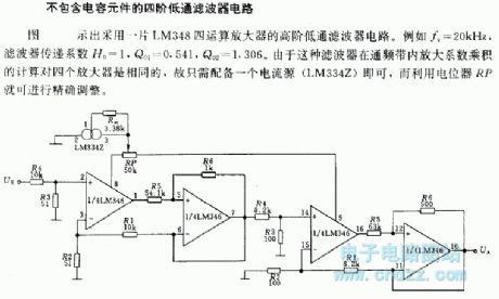
The figure shows a high-order low - pass filter circuit using a LM348 quad operational amplifier. For example fc = 20kHz, filter transfer coefficient H0 = 1, Q01 = 0.541, Q02 = 1.306. Because the amplification coefficient product calculation of filter in the pass band for the four amplifiers is identical, it is simply equipped with a current source (LM334Z), and precise adjustment can be carried out using the potentiometer RP.
(View)
View full Circuit Diagram | Comments | Reading(1281)
Automatically series resistor start three-phase motor circuit
Published:2012/10/11 21:07:00 Author:Ecco | Keyword: Automatically , series, resistor , start , three-phase motor

Pressing start button ST, the AC contactor 1KM and time relay KT get electric and action, normally open contact 1KM is closed and self-locked, the main contact 1KM action makes motor stator winding connect to resistor group R in series, motor M buck starts. At the same time, KT starts timing. When KT delay reaches the setting time, KT normally open contact close with a delay time, and 2KM coil gets electric, its main contacts 2KM action, then resistor R is shorted connected, the stator windings of the motor will be put into the rated voltage operation.
(View)
View full Circuit Diagram | Comments | Reading(3235)
Telephone Audio Interface
Published:2012/10/11 21:33:00 Author:muriel | Keyword: Telephone Audio, Interface
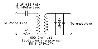
Audio from a telephone line can be obtained using a transformer and capacitor to isolate the line from external equipment. A non-polarized capacitor is placed in series with the transformer line connection to prevent DC current from flowing in the transformer winding which may prevent the line from returning to the on-hook state. The capacitor should have a voltage rating above the peak ring voltage of 90 volts plus the on-hook voltage of 48 volts, or 138 volts total. This was measured locally and may vary with location, a 400 volt or more rating is recommended. Audio level from the transformer is about 100 millivolts which can be connected to a high impedance amplifier or tape recorder input. The 3 transistor amplifier shown above can also be used. For overvoltage protection, two diodes are connected across the transformer secondary to limit the audio signal to 700 millivolts peak during the ringing signal. The diodes can be most any silicon type (1N400X / 1N4148 / 1N914 or other). The 620 ohm resistor serves to reduce loading of the line if the output is connected to a very low impedance.
(View)
View full Circuit Diagram | Comments | Reading(0)
| Pages:304/2234 At 20301302303304305306307308309310311312313314315316317318319320Under 20 |
Circuit Categories
power supply circuit
Amplifier Circuit
Basic Circuit
LED and Light Circuit
Sensor Circuit
Signal Processing
Electrical Equipment Circuit
Control Circuit
Remote Control Circuit
A/D-D/A Converter Circuit
Audio Circuit
Measuring and Test Circuit
Communication Circuit
Computer-Related Circuit
555 Circuit
Automotive Circuit
Repairing Circuit