
Circuit Diagram
Index 318
The bridge excitation circuit of digital pressure signal conditioner MAX1458
Published:2012/9/25 21:46:00 Author:Ecco | Keyword: bridge excitation , digital pressure, signal conditioner
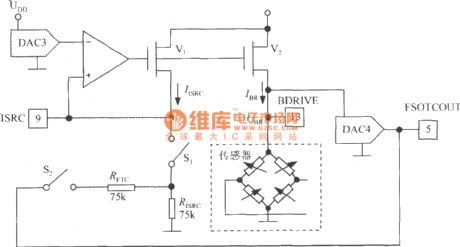
It uses DAC3 output to change the size of the sensor excitation current IBR and achieve fine full-scale calibration. IISRC is reference current which is set by RISRC and the voltage of pin 9. V1 and V2 form a mirror current source, and the current gain is 14 times which enables the excitation current IBR = 14IISRC. The IBR programming range is 0.1 ~ 2mA. The on-off state of analog switches S1, S2 is governed by the configuration register. Obviously, when the full-scale output voltage changes, DAC3 can compensate bridge output voltage by changing BR, thereby correcting the errors of the full scale. DAC4 is used to correct the error of full scale temperature coefficient.
(View)
View full Circuit Diagram | Comments | Reading(881)
Application circuit diagram of pulse width modulator LZ210
Published:2012/9/25 21:51:00 Author:Ecco | Keyword: Application , pulse width modulator
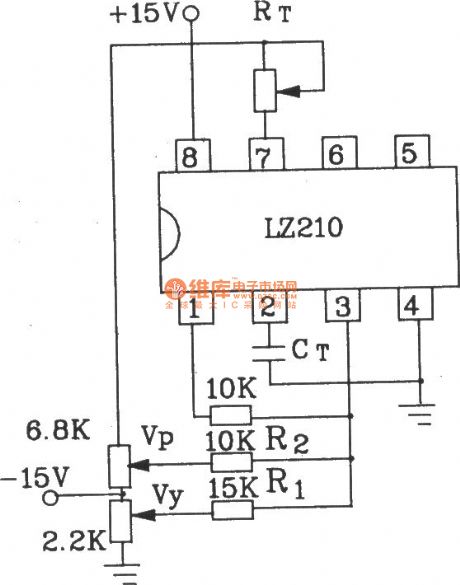
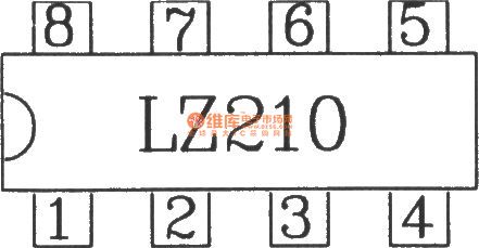
LZ210 is a dedicated long cycle pulse width modulator circuit,and it can convertthe voltage amplitude into a corresponding pulse width variations, and it is used withmatching with zero crossing trigger.The electrical parameters are shownas following:Supply Voltage: DC +15 V.Supply Current : ≤ l2mA.Ramp rate : ≥ 8V ( test conditions : Vcc = 15V)Control voltage:a. 0 ~ +8 V b. -4 ~ +4 VC. -8 ~ 0V d. -8 ~ +8 VOscillation cycle oscillation cycle : When Vcc = 15V, RT = 100kΩ ( see Figure 2-26 ).T = 0.06 ~ 0.12 ms (C t = 200p)T = 9 ~ 76 ms (C t = 0.1μ)T = 1 ~ 800 ms (C t = 1μ)T = 900 ~ 6 400ms (C t = 10μ)T = 24 000 ~ 120 000ms (C t = 220μ)The LZ210 uses 8-pin dual in-line package, and it isshown in the figure.
(View)
View full Circuit Diagram | Comments | Reading(1055)
Small power DC motor control component KCZ1 electrical schematic diagram and external wiring
Published:2012/9/25 22:08:00 Author:Ecco | Keyword: Small power, DC motor, control component , electrical schematic, external wiring
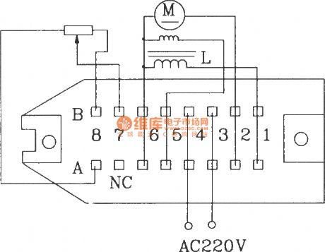
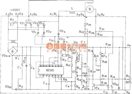
KCZ1 small power DC motor control components are suitable for small power DC motor speed control with 200V rated voltage, and it has negative feedback voltage and excitation output, and the components have small size and good speed regulation performance. The components can also be used as a DC power supply.The electrical parameters are shown as following:Grid voltage: (220 ± 10)%.Rated output voltage: DC 200V.Rated output current: 5A, the largest value is 9A (< 10ms ).Output excitation voltage: DC 220V.Output excitation current: 0.5A.External speed potentiometer : 2.2k12 multi-turn potentiometer.Speed ratio: up to 20:1.Allowing ambient temperature: - l0 ~~ +50 ℃.
(View)
View full Circuit Diagram | Comments | Reading(4853)
Car Battery Monitor 12 Volt
Published:2012/9/25 21:48:00 Author:muriel | Keyword: Car Battery, Monitor, 12 Volt


Here is an interesting Car Battery Monitor circuit of a low power electronic dc voltmeter circuit that can be used with car electric systems that run on 12 volt batteries. The voltmeter is an expanded scale type that indicates small voltage steps over the 10 to 16 volt range for 12 volt batteries.At the heart of the circuit is a ubiquitous dot-bar volt meter LM3914N (IC1). This IC is operated in the expanded-scale mode so that the circuit responds in the 10-16V range. IC1 outputs a steady voltage on pin 7 from the internal voltage reference. This is fed via voltage dividers VR2and R2 to the internal reference input pins(4&8) to set the range that the meter is sensitive to. The measured voltage is fed in on pin 5 via the voltage divider consisting of R1 and VR1. This divider scales the input voltage down to a range that is useful to IC1.
Car Battery Monitor schematic for 12V batteries
It is possible to set the meter to read equal steps across a variety of upper and lower voltages. Different colored LEDs can be used for the voltage level indicators(D1-D10). It will be necessary to have an adjustable regulated DC lab power supply and a good quality digital volt meter (DVM) to perform the calibration. Connect the external volt meter across pins 6 and 4 of IC1 and adjust VR2 for a reading of 1.2 volts. Center the settings of VR1 and VR3. If the span between the end points of VR1 is 4.5V, the circuit is ready to use as a 10.5 to 15V scale battery monitor. (View)
View full Circuit Diagram | Comments | Reading(1471)
Cashbox or Locker Alarm
Published:2012/9/25 21:48:00 Author:muriel | Keyword: Cashbox, Locker, Alarm circuit
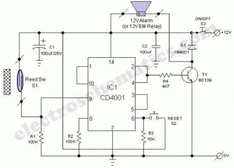
The locker alarm circuit or cashbox watcher can be used to protect a cashbox/locker from unauthorised access. This tried and tested design forms a fool-proof,remotely operated alarm/electromagnetic relay driver that receives its control signal from a standard reed switch. The circuit works off a 12V dc power supply.After construction, enclose the whole circuit, including the power supply (preferably with a backup facility) in a tamper proof metallic box and keep it in a secure location. For optimum safety, use key lock type switches for power (S3) and reset(S2) control. Now open your cashbox/locker and fix a strong permanent magnet in its door and the reed switch(S1) in the door frame so that when door is closed, the magnet is very near to S1. Now connect the terminals of reed switch to the input of the main circuit using a strong two-core cable.Operation of the locker alarm circuit, built around CD4001(IC1) is straight forward. When switch S3 is turned to ON state,the 12V supply is extended to the whole circuit.Normally, when cashbox/locker is closed, the reed switch is also closed due to the presence of bar magnet and hence the the output (at pin 10) of IC1 (Quad 2-input NOR gate pack) is in logic low state.When the cashbox/locker is opened, reed switch also opened and the output state changes to logic high level to enable the bistable latch realised using next two NOR gates (Final NOR gate is not used here). As a result, driver transistor (T1) activates to drive the output load. A ready made 12V electronic hooter or a standard 12V electromagnetic relay can be used as the output load. Push-to-on type switch (S2) is the reset switch for the bistable circuit.
Locker Alarm Circuit Diagram/Schematic
(View)
View full Circuit Diagram | Comments | Reading(2391)
Adjustable Timer circuit 1-10 minute
Published:2012/9/25 21:47:00 Author:muriel | Keyword: Adjustable, Timer circuit, 1-10 minute
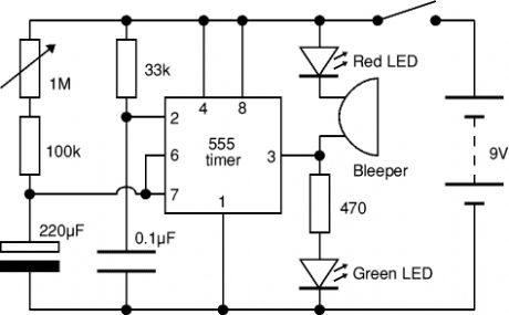
The Adjustable Timer circuit starts timing when switched on. The green LED lights to show that timing is in progress. When the time period is over the green LED turns off, the red LED turns on and the bleeper sounds. The time period is set by adjusting the variable resistor. It can be adjusted from 1 to 10 minutes (approximately) with the parts shown in the diagram. You can mark the times on a scale drawn on the box.Please note that the range of time periods is only approximate. With perfect components the maximum time period should be 4? minutes, but this is typically extended to about 10 minutes because the 220μF timing capacitor slowly leaks charge. This is a problem with all electrolytic capacitors, but some leak more than others. In addition the actual value of electrolytic capacitors can vary by as much as ±30% of their rated value.
Adjustable 10 minute timer schematic
(View)
View full Circuit Diagram | Comments | Reading(2027)
Mini Emergency Light circuit
Published:2012/9/25 21:47:00 Author:muriel | Keyword: Mini, Emergency Light
This is an LDR based Emergency Lampthat turns on a High watt White LED when there is darkness in the room. It can be used as a simple emergency lamp in the child’s room to avoid the panic situation in the event a sudden power failure.It gives ample light in the room.The circuit is too simple so that it can be enclosed in a small box. A 12 volt miniature battery is used to power the circuit. Two transistors T1 and T2 are used as electronic switches to turn on / off the white LED. When there is sufficient light in the room, LDR conducts so that the base of the PNP transistor T1becomes high and it remains off. T2 also remains off since its base is grounded. In this state, White LED remains off. When the light falling on the LDR decreases, it cease to conduct and T1 forward bias providing base current to T2. It then turns on and White LED switches on.
Mini Emergency Light Circuit Schematic
White LED used in the circuit is 1 watt High bright Luxeon LED. Since 1 watt White LED consumes around 300 milli ampere current, it is better to switch off the lamp after few minutes to conserve battery power. (View)
View full Circuit Diagram | Comments | Reading(2092)
USB Lamp circuit
Published:2012/9/25 21:46:00 Author:muriel | Keyword: USB, Lamp
Here is a simple USB lamp powered from the USB socket of PC. It uses 5mm high bright White LEDs to give ample light to work in the Keyboard if the room light is not sufficient. No PCB is required to make this circuit.The circuit is too simple and can be wired through lead-to-lead soldering. The LEds are connected to current limiting resistors R1 through R4.The cathode of all LEDs are joined together and soldered to the black wire of USB cable. Free leads of all the resistors are joined together and connected to the Red wire of USB cable. You can use a discarded USB cable with Class A type connector. Cut the Green and White wires of the USB cable and use only Red and Black wires. USB socket of PC provides 5 volts so that the LEDs give bright light. LEDs can be fixed in the Key board by drilling 5 mm holes.
USB Lamp Circuit Schematic
USB Cable
Class A USB Connector (View)
View full Circuit Diagram | Comments | Reading(1732)
Tilt Sensor Alarm Circuit
Published:2012/9/25 21:45:00 Author:muriel | Keyword: Tilt, Sensor Alarm
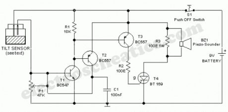
Ultra simple circuit of the tilt sensor alarm presented here can be fabricated using readily available inexpensive components. The circuit is a true transistor based design. Home made Tilt sensor for this circuit is an ordinary little glass/plastic bottle with two metal needles inserted through its cap, and a small quantity of water inside.You can also try your own ideas to make the tilt sensor. A 9V alkaline battery is enough for powering the whole circuit.
Tilt Sensor Circuit Schematic
Usually, transistor T1 is in inactive state. When the sensor assembly is tilted, both needles inside the sensor (bottle) are short circuited by the water and a positive voltage is available at the base of T1 and it becomes active. Activation of T1 causes the activation of next transistors T2 and T3. After this, T2 supplies constant bias for T1 to make it latched and T3 triggers the SCR(T4) which inturn energises the active piezo-sounder(BZ1). Once activated the circuit can be deactivated by depressing the power/reset switch S1.
Preset pot P1 is deliberately added here to adjust the circuit sensitivity. This may become necessary if you are trying a different (readymade) tilt sensor. Similarly,SCR(T4) and piezosounder (BZ1) may be replaced with near equivalent parts. Resistor R3 (100-150 Ohm) is optional. (View)
View full Circuit Diagram | Comments | Reading(1479)
LED Night Lamp circuit
Published:2012/9/25 21:44:00 Author:muriel | Keyword: LED, Night, Lamp
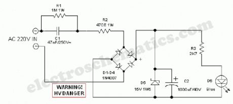
The design of the LED night lamp circuit (bedroom light) is similar to that of many commercially available products. However, the light circuit does not use any kind of bulky and noisy stepdown transformers, but a capacitive potential divider is inserted in a simple manner to provide a constant current for driving the light source. Here a high-efficiency, low current blue LED is used as the light source. The design is safe, simple and stable!
Night Lamp Circuit Schematic
When input power (AC 220V) is available, capacitor C2 is charged through C1 and R2 and bridge rectifier assembly D1-D4. Zener diode D5 limits the voltage across C2 to a safe value of near 15V. This low voltage dc supply is then fed to the LED (D6) via current limiting resistor R3. When the input supply is removed, LED stays on unchanged for a short time and then diminishes gradually. No instant darkness when the supply is switched off!
After construction, enclose the circuit in a small plastic box. Drill a 5mm hole in the centre of the enclosure and fit the LED in a suitable LED holder in the 5mm hole. Finally fit a supply input socket and, optionally an on/off switch at the rear/side of the enclosure.
WARNING! Great care should be taken when working with this led night lamp circuit since it is connected directly to the fatal mains supply. (View)
View full Circuit Diagram | Comments | Reading(2776)
Line Following Robot Sensor
Published:2012/9/25 21:44:00 Author:muriel | Keyword: Line Following, Robot, Sensor

This Line Following Robot sensor or surface scanner for robots is a very simple, stamp-sized, short range (5-10mm) Infrared proximity detector wired around a standard reflective opto-sensor CNY70(IC1). In some disciplines, a line following robot or an electronic toy vehicle go along a predrawn black line on a white surface. In such devices, a surface scanner, pointed at the surface is used to align the right track.IC1 contains an infrared LED and a phototransistor. The LED emit invisible infrared light on the track and the phototransistor works as a receiver. Usually, black colored surface reflects less light than white surface and more current will flow through the phototransistor when it is above a white surface. When a reflection is detected (IR light falls on the phototransistor) a current flows through R2 to ground which generates a voltage drop at the base of T1 to make it conduct. As a result, transistor T2 start conducting and the visual indicator LED(D1) lights up. Capacitor C2 works as a mini buffer.After construction and installation, the scanner needs to be calibrated. Initially set P1 to its mechanical centre position and place the robot above the white portion of the track. Now slowly turn P1 to get a good response from D1. After this, fine tune P1 to reduce false detection caused by external light sources. Also ensure that the LED remains in off condition when the sensor module is on the blackarea. Repeat the process until the correct calibration is achieved.
The red color LED (D1) is only a visual indicator. You can add a suitable (5V) reed relay in parallel with D1-R4 wiring after suitable alterations to brake/stop/redirect the robot. Similarly, the High to low (H-L) transition at the collector of T2 can be used as a signal to control the logic blocks of the robot. Resistor R1 determines the operating current of the IRLED inside IC1. The sensing ability largely depends on the reflective properties of the markings on the track and the strength of the light output from IC1.
Line Follower Robot Scanner Schematic
(View)
View full Circuit Diagram | Comments | Reading(3180)
Door Timer Circuit with Alarm
Published:2012/9/25 21:42:00 Author:muriel | Keyword: Door Timer, Alarm circuit

We are in a digital era! Now we can add some intelligence to our doors and gates without too much investments. Just assemble this little door timer circuit built around a few cheap and simple components and link it to any door/gate as per your requirement and taste. If the door/gate remains in open condition for a prefixed time an acoustic sounder starts beeping to raise an alert. Enough?At the heart of the circuit is CD4060, which is a 14-stage ripple-carry binary counter/divider plus oscillator. Here CD4060 is configured as an independent timer. In standy by state, ie when switch S1 is in closed condition, the reset terminal ( pin12) of CD4060 is at a high level and the timer is in inactive mode. When the door is opened, S1 also opened as per the mechanical arrangement and CD4060 gets activated.After a short period,transistor T1 conducts to power the active piezo-sounder. Red LED in parallel with the piezo-buzzer also lights up instantly. When the door(and hence S1) is closed, circuit returns to standby state automatically.The open door alarm circuit works off 9V (PP3/6F22) battery supply. Assemble the circuit on a small PCB and enclose in a plastic box of appropriate size. Mount the switch S1 in the door/gate frame and connect it to the circuit through external cable. If possible use a key-lock type switch for power on/off function (S2).
Note: Preset delay time can be changed by changing the value of timing resistor R3. SK1 is an optimised connection terminal for attaching a standard 6-9Volt electromagnetic relay.
Door Timer Circuit Schematic
(View)
View full Circuit Diagram | Comments | Reading(1403)
Motion Sensor Switch for alarm, light or water sprinkler
Published:2012/9/25 21:42:00 Author:muriel | Keyword: Motion Sensor, Switch, alarm, light, water sprinkler

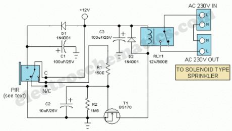
The Motion Sensor Switch circuit is a motion sensor controlled automatic water sprinkler but you can easily add an alarm/light function too. Before beginning the construction contact your nearest electronics component vendor and procure a readymade box-type Passive Infrared (PIR) Motion Sensor unit. Such units, packed in a compact enclosure with power input and relay output terminals are widely available. In prototype, an unbranded (Made in China) PIR Motion sensor with the following specifications are used.
Detection Range:10Meter Maximum
Supply Input:12V DC, <500mA
Relay Output :Common(C),Normally Closed(N/C),Normally Opened(N/O)
Relay ON time: 15 Secs (Not Adjustable)
Now install the PIR module hanging from a 3 metre high mast (to cover 10 metre radius area) and connect its supply and relay terminals to our finished and enclosed circuit, observing right polarity. A 4-core screened cable can be used for this interconnection. Power the circuit from a regulated 12VDC adaptor/solar power box.
Whenever the PIR module detect movement of a live body its relay output toggles and the switching mosfet (T1) in the circuit is switched to on via resistor R1 and related parts. As as result, the EM relay at the output of T1 is activated and the electric sprinkler gets its supply through the relay (RLY1) contacts. This contacts (or spare contacts) can also be used to activate a high-power warning alarm.
Motion Sensor Switch Circuit Schematic
(View)
View full Circuit Diagram | Comments | Reading(4361)
Electronic GateKeeper circuit
Published:2012/9/25 21:41:00 Author:muriel | Keyword: Electronic GateKeeper
This circuit can do the job of a Gatekeeper and intimates you if someone passes through the gate. The alarm can be an AC bell or a Lamp. The alarm turns on for 1 minute and stops if the light barrier is restored again.Infrared rays are used as the light barrier to activate the alarm system based on a Phototransistor. The high gain NPN Darlington phototransistor L14F1 conducts when its face is illuminated with IR rays. This brings its collector to ground potential. IC1 is used as a simple voltage comparator with a potential divider R2 and R3 connected to its inverting input. So that half supply voltage (6 volts) is available to its inverting input. Its non inverting input is connected to the collector of the phototransistor. Normally the output of IC1 will be low since T1 is conducting. When the IR beam breaks, the collector of T1 becomes high and the voltage at the non inverting input of IC1 increases above the voltage at the inverting input and output becomes high. This triggers the relay driver T2 and relay turns on. Capacitor C1 gives a short delay at the non inverting input of IC1 to prevent false triggering. Capacitor C2 keeps the base of T2 high for a short time even if the IR rays restore.
Electronic Gate Keeper Schematics
(View)
View full Circuit Diagram | Comments | Reading(828)
Flashing LED circuit with LDR
Published:2012/9/25 21:40:00 Author:muriel | Keyword: Flashing, LED circuit, LDR
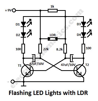
In this flashing led lights circuit, the LDR or photoresistor is connected in such way that when the light intensity varies it will influence the flashing frequency and the brightness of the LEDs. T1, T2 = BC547, BC548, BC549 (any NPN transistor).
You can arrange the LEDs D1 to D4 in cross in order to obtain interesting effecs. The whole flashing led circuit is powered from a 9 volt battery and can be built small enough so it will fit in a matchbox.
Schematic of Flashing Lights with photoresistor
(View)
View full Circuit Diagram | Comments | Reading(2874)
Retriggerable Monostable Circuit
Published:2012/9/25 21:39:00 Author:muriel | Keyword: Retriggerable, Monostable Circuit
CD 4047 is the low power Monostable / Astable Multivibrator that requires only an external capacitor and a resistor to give the output pulses.The values of these components determine the output pulse width in the Monostable mode and output frequency in the Astable mode.Monostable mode
Monostable mode can be obtained by triggering the + input of the IC using a low to high pulse or by a high to low pulse at the – input. The IC can be retriggered by applying simultaneous low to high pulse in both the + and – inputs.
Astable mode
This can be obtained by keeping a high / low level at the Astable input. Output frequency depends on the timing components.
Pin connections of CD4047
CD 4047 is a low power CMOS IC that can operate between 3 to 15 volts DC.
Retriggerable Monostable Circuit diagram
(View)
View full Circuit Diagram | Comments | Reading(1004)
Variable Zener Diode
Published:2012/9/25 21:38:00 Author:muriel | Keyword: Variable, Zener Diode

This variable Zener diode circuit acts like a Zener diode with a breakdown voltage adjustable in a vast domain. The current through the voltage divider R1 and R2 must be higher current through the voltage divider should be higher compared with that of the transistors base. It depends only by R1 and has been set to 8 mA. The breakdown voltage of this simulated Zener diode is adjustable between 5V and 45V. The circuit begins to stabilize at a current of 15 mA. The maximum current for a Zener is 4.7V/250mW is around 50 mA.
If you need to stabilize voltages above 15V, the transistor must be mounted on a heatsink. This measure must be taken if the current consumption of the circuit reaches 40-50 mA.
Variable Zener Circuit Schematic
(View)
View full Circuit Diagram | Comments | Reading(2631)
Voltage Stabilizer circuit with LDR (photoresistor)
Published:2012/9/25 21:37:00 Author:muriel | Keyword: Voltage Stabilizer, LDR, photoresistor
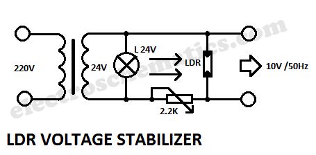
This is a very interesting a.c. voltage stabilizer that uses a LDR or photoresistor to stabilize an alternating current (AC).If the voltage increases then the brightness of the light bulb increases too and the LDR’s resistance will decrease. If the potentiometer is properly adjusted then the AC voltage will stay constant.
The optimal adjustment of potentiometer is done experimental, feeding the circuit with a variable ratio transformer, which can simulate variations of voltage network.
LDR voltage stabilizer circuit schematic
(View)
View full Circuit Diagram | Comments | Reading(1434)
Vibration Sensor/Detector circuit
Published:2012/9/25 21:37:00 Author:muriel | Keyword: Vibration Sensor,Detector

With the help of a simple ceramic piezo-electric detector it is possible to assemble an interesting and useful Impact sensor unit,which can be used to detect impact and vibration on doors, showcases, windows etc. The shock sensor (Ceramic piezo-electric detector) uses a “unimorph” diaphram, which consists of a piezo-electric ceramic disk laminated to a metal disk. The sensor supplies a voltage proportional to the acceleration of the impact or vibration, for example 40mV/G ie output is near 2V for 60G impact.Here a low voltage, low current Impact sensor unit is realised using a standard ceramic piezo-electric detector which drives a monostable multivibrator (IC1) circuit to activate a npn silicon transistor (T1). Open collector output of this transistor switch can be interfaced to an external alarm/switch circuit for further processing. Since current consumption of the circuit is very low (from 5 to 6 mA only) any common 3V button cell can be used to power the sensor unit.When an impact is sensed, the monostable drives the transistor switch to ON , for a finite duration determined by the incircuit values of RC timing components R3 and C2.
The M74HC123 (IC1) is an high speed DUAL retriggerable CMOS MONOSTABLE MULTIVIBRATOR (MMV) fabricated with silicon gate C2MOS technology, with all inputs protected against static discharge and transient excess voltage. There are two trigger inputs, negative edge and positive edge. Here, only one monostable part with positive edge triggering (pin 2) is used. After triggering, the output maintains the monostable state for the time period determined by the external resistor R3 and capacitor C2.
Vibration/Impact Sensor Circuit Schematic
(View)
View full Circuit Diagram | Comments | Reading(2110)
Network RJ45 Cable Tester circuit
Published:2012/9/25 21:36:00 Author:muriel | Keyword: Network, RJ45, Cable Tester

This is a multifunction RJ45 network cable tester. It is the design of the network cable (RJ45) test, and telephone (RJ11). It is cheap and easy to use. It works for network, telephone, cable with RJ45 half “Registered Jack” plug immediately indicate whether a crossover network cable or straight, flashing a yellow or green LED. If something is broken or if you press the button, the tester is in line with the wire test. How does the network cable tester circuit work?The top RJ45 connector sends signals to each of its eight legs. The lower RJ45 connector receives signals from the top RJ45 connector created by the wire.
When the red LED above the orange light LED bar shows the pins in the top RJ45 connector sends a test signal, and when the bottom of the red LED illuminates orange LED bar indicates which of the eight dioceses of the bottom RJ45 connector signal receives in this state where the wire is broken or not connected, none of LEDs in the LED bar will light up orange.
If a short circuit between two or more wires, more than an orange LED lights up when the bottom red LED lights. Each time the button is the active output pin.RJ45 Cable Tester Specifications
For network cable (RJ45) and telephone (RJ11) tests.
Similar test can double-twisted cables 1,2,3,4,5,6,7,8 and Ground, meanwhile, can judge wrong connection, short circuit and open circuit.
ON / OFF button.
With four LED indicator.
Composing the master and remote two tests that can take a role in the testing easier.
Power by 9V battery.
Compact, durable design with a black plastic bag with zipper for storage.
Cable RJ45 network and RJ11 phone port
RJ45 Network Cable Tester Circuit Schematic
(View)
View full Circuit Diagram | Comments | Reading(2869)
| Pages:318/2234 At 20301302303304305306307308309310311312313314315316317318319320Under 20 |
Circuit Categories
power supply circuit
Amplifier Circuit
Basic Circuit
LED and Light Circuit
Sensor Circuit
Signal Processing
Electrical Equipment Circuit
Control Circuit
Remote Control Circuit
A/D-D/A Converter Circuit
Audio Circuit
Measuring and Test Circuit
Communication Circuit
Computer-Related Circuit
555 Circuit
Automotive Circuit
Repairing Circuit