
Circuit Diagram
Index 321
Automatic Lawn Light with LDR
Published:2012/9/24 22:26:00 Author:muriel | Keyword: Automatic,Lawn Light,LDR
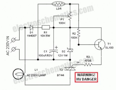
Circuit of a compact and true solid-state automatic lawn light is described here.The circuit can be used to switch on incandescent garden light bulbs at desk and switch off them at dawn. A 10 mm encapsulated light dependent resistor (LDR) here works as the twilight detector.The whole circuit can be housed in a very small plastic cabinet.For powering the circuit AC 230V household supply is needed. With a little skill and patience, you can easily modify this circuit to drive a number of white LED strings, instead of the incandescent bulb load at the output.When ambient light is normal, transistor T1 is reverse biased by the low resistance of LDR. Multi-turn palstic trimpot P1 sets the detection sensitivity. If ambient light dims, transistor T1 turns on to drive the triac T2. Now the lamp load at the output of T2 energises.When the ambient light level restores, circuit returns to its idle state and light(s) switched off by the circuit.Working voltage for the circuit is derived directly from the AC supply input through components D1, R1, D2 and C1. This obviates the requirement of a bulky and noisy step-down transformer.
If you wish to operate the light bulb(s) on a little reduced power,just replace the triac T2 with a suitable silicon controlled rectifier (SCR). This may give a long life to the incandescent load. Finally, the LDR should not be mounted to receive direct sunlight. It may be mounted at the top of the enclosure, pointing to the sky say southwards.
LDR Lawn Lights Circuit Schematic
(View)
View full Circuit Diagram | Comments | Reading(4152)
Water Switch Sensor Circuit
Published:2012/9/24 22:25:00 Author:muriel | Keyword: Water,Switch,Sensor
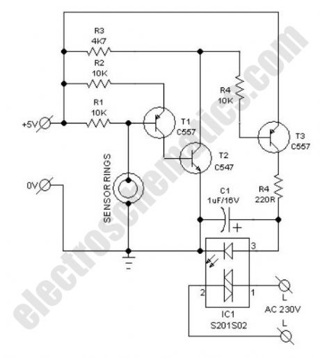
Possible applications for this water switch circuit: rain alarm, watertap leak detector, water level sensor for bathroom water heaters, wetness checker for flower pots and more. This circuit is nothing but a water activated solid-state switch (S201S02) capable of driving ac mains operated loads.How does the water switch circuit worksWorking principle of this circuit is very simple. When the sensor rings are bridged by water, an isolated electric switch turns on to activate the load (an alarm, for instance) connected through its switching contacts. Here, the renowned S201S02 solid-state relay (IC1) is wired as the electronic switch. Any low current 5VDC power unit can be used to feed input supply to the whole circuit.As clearly indicated in the circuit diagram, two closely spaced metal rings are used as the water sensor mechanism. However, one can use two metal needles/injection needles to make the sensor.
Water Switch Circuit Schematic
(View)
View full Circuit Diagram | Comments | Reading(2815)
X’Mas LED Decoration circuit
Published:2012/9/24 22:25:00 Author:muriel | Keyword: X’Mas,LED Decoration
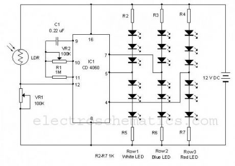
Using this simple circuit, you can make an 18 LED flasher to decorate the X’Mas Tree. The White, Blue and Red LEDs flash at different rates to give a colorful display. It is a light sensitive circuit so that it will turn on in the evening automatically and stays on till morning.The circuit uses the popular Binary counter IC CD 4060 to flash the LEDs at different rates. Components C1, VR2 and R1 form the oscillator and the output pins 7, 5 and 4 become high / low sequentially. When one output turns high, a set of 3 LEDs turn on and when the same output turns off, the second set turns on. This sequence is similar in the other two sets of LEDs also but with different timings. The speed of the Flashing can be controlled through VR2.
Christmas Light Decoration Circuit Schematic
(View)
View full Circuit Diagram | Comments | Reading(3171)
Do It Yourself Solid State Relay
Published:2012/9/24 22:24:00 Author:muriel | Keyword: Solid State, Relay
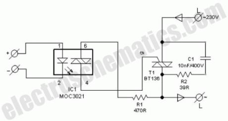
One advantage of solid-state relay (SSR) over conventional electro-magnetic relay (EMR) is its tear and wear free operation. S201S01 from Sharp is a good example. Here is the circuit diagram of a DIY SSR project, which is in fact an isolated triac power controller.The switching output from any dc circuit can be connected to pin 1 of opto-isolator (IC1) through a suitable current limiting resistor. Pin 2 of IC1 is grounded.Pin 6 of IC1 is connected to one main terinal of Triac (T1) through resistor R1 and pin 4 drives the gate terminal of T1.
To limit the rate of change of voltage, a snubber circuit (R2-C1) is added across T1.When current passes through the internal LED of IC1, internal diac is triggered and the diac provides the gate pulse to T1. Now T1 is fired to drive the ac mains operated load at its output.
After construction of the solid state relay on a common pcb, enclose the whole circuit in a very small ABS case. Now drill suitable holes to mount four labelled input and output terminals. Since switching is accomplished by triac T1, don’t touch the internal parts while AC supply is plugged in.
DIY Solid-State Relay Circuit Schematic
(View)
View full Circuit Diagram | Comments | Reading(2323)
Automobile White LED Light
Published:2012/9/24 22:23:00 Author:muriel | Keyword: Automobile,White,LED Light
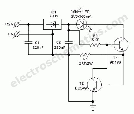
Without any dedicated buck converter/white LED driver IC, you can safely drive many standard Hi-efficieny white LED modules using the battery power available in automobiles. Here is a safe and simple white LED driver designed for 12V automobiles.In the Automobile White LED Light circuit, fixed voltage regulator IC1 (7805) provides a steady voltage of 5V across C2. Resistors R1 limits the current flow through the white LED D1 (3v6/350mA) with the help of transistor T1 (and T2), ie components R1, T1 (and T2) provide a constant current to D1. Use a good heat sink for T1. This LED unit gives a constant light output for input voltages ranging from 8 to 18 volts!
Auto White LED Circuit Schematic
(View)
View full Circuit Diagram | Comments | Reading(2433)
Light Fence Security Beeper
Published:2012/9/24 22:22:00 Author:muriel | Keyword: Light Fence,Security,Beeper

General purpose hobby circuit of a simple light fence security beeper is presented here. This circuit can be used as a door alarm, gate alarm, pathway alarm, etc. Any 12 Volt dc power supply can power the whole circuit.Working of this circuit is straight forward. In standby mode photo transistor T1 receives light from the green LED (D1) and T1 conducts to disable the gated low-frequency astable built around IC1(4093).When this light path is interrupted by any object in the path, T1 stops conducting and IC1 is switched by the low level at its input point (pins 12&13). As a result the piezo-buzzer starts beeping at a slow rate determined by the in circuit values of R3, R4 & C1. Red LED (D2) is a visual warning indicator.With the help of suitable reflector and lens assembly, length of the light path can be increased. A minimum of 1 to 2 metres is possible with a high-bright green LED as D1. A laser pointer can also be used as the light source.
Light Fence Alarm Circuit Schematic
(View)
View full Circuit Diagram | Comments | Reading(2728)
Low Cost LED Blinker circuit
Published:2012/9/24 22:21:00 Author:muriel | Keyword: LED, Blinker
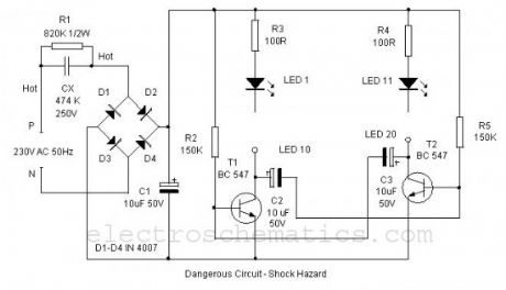
Here is a simple LED Alternate flasher for decoration purpose. The 20 High bright LEDs flashes alternately giving a brilliant colour display. The circuit is low cost and derives DC directly from AC without using a step down transformer. The design is too simple so that the circuit can be assembled on a small piece of common PCB.Power to the circuit is derived from 230 Volt AC through AC capacitor CX which is used to step down 230 volt AC to low volt AC. 474 K 250 Volt AC capacitor gives around 20 volts AC and 40 mA current. This low volt AC is rectified through the Bridge rectifier D1 through D4 and filtered by C1.
The LED driver is an Astable multivibrator using two NPN transistors T1 and T2.The circuit works on the principle of charging and discharging of capacitors C2 and C3. Current from the positive rail flows through first set of LEDs 1- 10 to the collector of T1 through resistor R3. Resistor R3 limits current through the LEDs to protect them.
The current through R3 and LEDs charges capacitor C2. It then discharges through the base of T2 and resistor R5. This gives base current to T2 and it conducts. As a result second set of LEDs 11-20 lights. As the Capacitor C2 discharges completely, T2 turns off and LEDs 11-20 also turns off. The same thing happens in the other side also. This gives alternate flashing of LEDs. Thus the flashing effect is produced through the switching of T1 and T2 by the charge from capacitors.
Low cost LED Blinker circuit diagram
(View)
View full Circuit Diagram | Comments | Reading(2177)
Battery Backup Circuit
Published:2012/9/24 4:25:00 Author:muriel | Keyword: Battery Backup

This Battery backup circuit can be added to surveillance systems like alarms to power the circuit during Mains failure. The battery backup will immediately take up the load without any delay.The circuit is simple to construct. Regulator IC 7809 gives 9 volts regulated DC for powering the circuit as well as to charge the rechargeable battery. LED indicates the power on status. When the mains power is available, diode D1 forward biases and passes current into the battery through R2. Value of R2 is selected to give 90 mA current (9/100 = 0.09A) for slow charging. When the mains power fails, D1 reverse biases and D2 forward biases and backup the circuit. The same circuit can be used in circuits having 6 volt 7.5Ah battery. For 12 volt battery, use 7814 regulator IC and 14 Volt input.
Battery backup circuit diagram
(View)
View full Circuit Diagram | Comments | Reading(4451)
Keyhole Finder circuit
Published:2012/9/24 4:24:00 Author:muriel | Keyword: Keyhole,Finder

This 3 volt Lithium cell operated LED flasher can be used as a key hole finder in darkness. A small lithium button cell can power the circuit more than 6 months continuously with day and night flashes. The circuit can also be used in key stand to search key in darkness.
The circuit is a simple oscillator comprising two complementary transistors BC 547 and BC557. These NPN and PNP transistors are wired as a simple oscillator with components C1 and R1 so that the LED flashes based on the charging and discharging of C1. Current consumption of LED is very low so that a normal 3 volt lithium battery can power the circuit for long time. A miniature 12 volt battery used in Car remote can power the circuit more than 2 years continuously.
Keyhole Finder Circuit
Use a high bright transparent 5 mm Yellow LED and fix the unit near the keyhole.?
7 Responses to “Keyhole Finder circuit”
(View)
View full Circuit Diagram | Comments | Reading(2735)
Relay Driver circuit
Published:2012/9/24 4:24:00 Author:muriel | Keyword: Relay,Driver
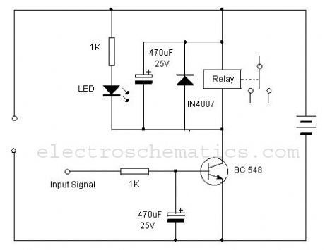
One of the serious problems in relay operated circuits is the relay clicking or chattering during the on/off of the relay driver transistor. This problem is severe if the input circuit is a light / temperature sensor. During the transition of light / temperature levels, the relay clicks which may cause sparking of contacts. By using a simple tip, this problem can be avoided.Below is the circuit of a Relay driver using the NPN transistor BC 548. The relay is connected between the positive rail and the collector of the transistor. When the input signal passes through the I K resistor to the base of the transistor, it conducts and pulls the relay. By adding a 470 uF electrolytic capacitor at the base of the relay driver transistor, a short lag can be induced so that the transistor switches on only if the input signal is persisting. Again,even if the input signal ceases, the transistor remains conducting till the capacitor discharges completely. This avoids relay clicking and the offers clean switching of the relay.
Relay Driver Circuit
(View)
View full Circuit Diagram | Comments | Reading(3056)
Electronic Doorbell Light Schematic
Published:2012/9/24 4:23:00 Author:muriel | Keyword: Electronic, Doorbell, Light

This 6V battery operated doorbell light circuit can be connected in parallel with any existing AC230V doorbell. When anyone push the doorbell switch, the bell sounds as usual and ac mains supply available across the doorbell is routed to the input of this circuit through an opto-coupler(IC1).Conduction of IC1 triggers a monostable, wired around the good old 555 timer (IC2). As a result the high-bright white LED (D2) at the output of IC2 is switched on for a short time. This circuit is highly useful at night/midnight as it gives sufficient indoor light to help you locate switches for room lamp/porch light, etc. On/Off duration of the LED light can be increased/decreased by increasing/decreasing the value of C2.The electronic doorbell light circuit is fully safe because it is perfectly isolated from the fatal ac mains supply by IC1. However, keep to avoid accidental contacts with the front end of the circuit, which is directly connected to the ac supply. Use of a good and convenient ABS enclosure is recommended for this doorbell light unit.
Electronic Doorbell Light Circuit Schematic
?
12 Responses to “Electronic Doorbell Light Schematic”
(View)
View full Circuit Diagram | Comments | Reading(2001)
Quartz Controlled Bedroom Light Switch
Published:2012/9/24 4:22:00 Author:muriel | Keyword: Quartz,Controlled, Bedroom Light, Switch


Here is an ultra simple automatic light switch circuit for bedrooms. After construction,connect the input terminals of this circuit in parallel to the internal buzzer terminals of a Quartz-Alarm Clock. When the clock alarm is activated at a time set by the user, electromagnetic relay in the circuit is energised for a short duration, controlled by the timer IC 555.Contacts of the relay can be used to switch on a bedlamp, table lamp or similar electric light loads. The circuit works off unregulated 12V.U se any12VDC/500mA rated standard ac mains adaptor.When the clock alarm rings, input pulses are fed to the trigger input point (T1+Pin2) of IC1, through an RC filter (C1,R1&C2). Here IC1 is wired as a monostable and dc voltage at its output (Pin 3) terminal goes high instantly after receiving a trigger,and remains in the condition for about10 seconds, as configured by the components values of R3 and C3.
Output from IC1 directly drives the low current relay RL1 through diode D1. Note that diode D2 is here used as a freewheeling diode to suppress the counter emf generated during relay switching.
Automatic Light Switch Circuit Schematic
?
7 Responses to “Quartz Controlled Bedroom Light Switch”
(View)
View full Circuit Diagram | Comments | Reading(1975)
Quartz 1Hz Timebase
Published:2012/9/24 4:21:00 Author:muriel | Keyword: Quartz,1Hz, 1Hz

Here is one basic circuit of a simple but accurate 1Hz timebase generator built around a standard Quartz clock circuit board. Just lift the clock PCB from any cheap quartz clock and carefully remove all extra components like the drive coil, buzzer, alarm switch and clock mechanism (quartz movement), etc.Next wire the circuit as shown in the schematic diagram, observing correct connection points and polarities, and power it from a 5VDC supply. Precision 1Hz clock signal generator is now ready to serve you. With suitable modification(s) at the output you can use this circuit to drive blinkers, beepers and microcontroller based ciruits.
Notes:
1. Stable 1.5-1.6 VDC supply for the clock PCB is derived from the 5VDC input supply with the help of componets R1, D1 and C1. Only use a 10mm Red color (Vf=1.6V) LED for D3.
2. Drive coil outputs (L1&L2) of the clock PCB are joined together to get one second pulse output with the help of two schottky diodes (D1&D2). Such low-drop diodes are crucial for this circuit.
3. The circuit is inverting output type and hence, the output is normally at high level,and pulses low once a second.By adding a second (optional) transistor, this can be reversed, ie non inverting, so that the output is normally at low level, and pulses high once a second.
Quartz 1Hz Timebase Generator Circuit Schematic
?
4 Responses to “Quartz 1Hz Timebase”
(View)
View full Circuit Diagram | Comments | Reading(4433)
Handy Pen Torch circuit
Published:2012/9/24 4:21:00 Author:muriel | Keyword: Pen, Torch

This easy to construct “Handy pen torch” electronic circuit and low component count, uses two power white LEDs for lighting. Low volt (4.8V dc) supply available from the built in rechargeable Ni-Cd battery pack is first converted into two channel (independent) constant current sources by two pieces of the renowned precision adjustable shunt regulator chip LM334 (IC1 and IC2).Around 25 mA at 3.6 volt dc is available at the output of these ICs. This regulated dc supply is used to drive two power white LEDs D4 and D6. Resistors R3 and R5 limlits the output current (and hence the light output) of IC1 and IC2 circuits respectively.Besides these components, one red color LED (D2) is included in the main circuit which works as a battery charging supply input indicator.Resistor R1 limits the operating current of this LED .
Pen Torch Electronic Circuit Schematic
Diode D1 works as an input polarity guard cum reverse current flow preventer. Capacitor C1 is a simple buffer for circuit stabilization. After succesful construction, preferably on a small piece of general purpose PCB, enclose the whole circuit in a suitable and attractive pen torch cabinet. If necessary, drill suitable holes in the cabinet to attatch the dc socket, on/off switch and the input indicator etc. In prototype,commonly available 4.8 volt/500mah Ni-Cd battery pack (for cordless telephones) is used.
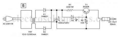
One very simple but reliable ac mains powered battery charger circuit for the handy pen torch is also included here. Basically the pen torch circuit is a constant current charger wired around Transistor T1 (BC636), powered by a 12v/350mA step down transformer and associated componentsD1, D2 and C1.
AC mains powered battery charger for the pen torch
Unregulated 12 volt dc available from the input power convereter circuit, comprising step down transformer(TRF), rectifier diodes (D1,D2) and filter capacitor (C1), is fed to T1 through a current limiting resistor R1. Grounded base PNP transistor T1 here works as a constant current generator. With 22 ohm resistor for R1, the charging current available at the output of the charger is near 50 mA.
Red LED (D3) provides a fixed voltage reference to the base of T1, with the help of resistor R2. (During charging process, Diode D1 in the main circuit prevent reverse current flow from the battery pack when charging input supply is absent.) After construction of the pen torch circuit, fit the assembled unit inside a small plastic enclosure for safety and convenience.?
2 Responses to “Handy Pen Torch circuit”
(View)
View full Circuit Diagram | Comments | Reading(2627)
Sensitive Freezer Alarm with Buzzer
Published:2012/9/24 4:20:00 Author:muriel | Keyword: Sensitive, Freezer Alarm

Here is a simple freezer alarm circuit, but ultra sensitive with a buzzer. The circuit raises an audio alert when the temperature inside the freezer box goes up above a preset level. The circuit requires 9V dc supply and can power from a standard 9V alkaline battery.A negative temperature co-efficient type (NTC type) small thermistor (R1) here works as the freezer status sensor. Related components (T1 and T2) are used to drive a 6 to 9V rated mechanical buzzer. When the sensor detects a temperature shoot, the buzzer starts beeping and remains in that condition, till power to the circuit is removed. For this on/off plus reset function any small dc toggle switch can be inserted at the positive rail.
Freezer Alarm Circuit Schematic
?
2 Responses to “Sensitive Freezer Alarm with Buzzer”
(View)
View full Circuit Diagram | Comments | Reading(1423)
Light Dependent Resistor PC Desk Lamp
Published:2012/9/24 4:19:00 Author:muriel | Keyword: Light, Dependent Resistor, PC, Desk Lamp
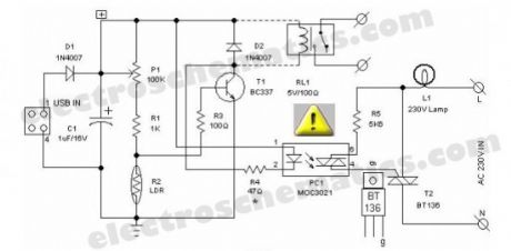
Most of the PC desk lamps available in the market light up whenever there is an input power. These don’t take into account whether there is a real need for the light or not. Here is an intelligent PC desk lamp circuit that overcome the problem.It senses the light level in the room to determine the actual need for light and lights up only if required. It is designed to work with the PC and remains on only when the PC in the table is in working state. It uses MOC3021.Front end of the circuit is powered by the 5volt dc supply available from the usb port of the PC. When circuit is powered, the light sensor LDR (R2) resistance is low if there is sufficient light and thus most of the base current of transistor T1 finds an alternative easy path via LDR and T1 remains cutoff. While during dakness, the LDR behaves almost as an open circuit, and the current through sensitivity control preset pot (P1) and assosiated resistors (R1,R3) flows into the transistor’s base. As a consequence, T1 conducts to energise the opto-triac PC1. Next, the lamp driver triac T2 is fired through the opto-triac PC1 and switch on the power supply to the incandescent lamp.The circuit can be constructed on a medium size PCB. After construction, enclose the finished circuit in a well insulated plastic cabinet. Then drill holes for mounting the ‘B’ type USB input socket, power switching termianls and the LDR etc. This circuit is meant for use in conjuction with Personal Computers to switch on an associated light sensitive table lamp/similar load. An optional electro magnetic relay can also be wired at the output of the circuit to switch heavy electrical load(s). For interconnection between PC and the control circuit, use a standard USB cable with an ‘A’ type connector on one end and a ‘B’ type connector at the other end.
LDR USB Desktop Lamp Circuit Schematic
Warning! This LED PC Desk Lamp circuit is perfectly isolated from mains. However some parts of the circuit carries dangerously high voltages. So ,while testing,using or repairing take extreme care to avoid the fatal electric shock.?
6 Responses to “Light Dependent Resistor PC Desk Lamp”
(View)
View full Circuit Diagram | Comments | Reading(1698)
Step switch selector
Published:2012/9/24 4:19:00 Author:muriel | Keyword: Step switch, selector
As the name indicates, the step switch selector circuit is intended to choose one of up to four analogue switches, which it does with the aid of some less expensive components. It works off a regulated 5 volt dc supply and draws a current of few milliamperes. It may be used for a variety of applications, such as stepped volume controller, sequential power switcher, and so on. Note that although the prototype uses an ordinary push to on type micro switch, a different kind of sensor may also be used, provided its specification is known and suits the present circuit.
how does the step switch works?
The stepping switch circuit consists basically of a key bouncer, a clock oscillator, 4 stage counter and four analog switches. When power is first applied, the RC network (R5,C4) connected to the reset input (pin15) forces the Q0 output (pin3) of IC2 to be initially active and this standby state is indicated by D2. An oscillator, wired around two gates of IC1, is connected to the clock input(pin 14) of the IC2.
Here, the frequency is near 1Hz with the component values shown (R3=10K & C2=100uF). When S1 is in off state, the counter IC2 remains inactive. If the push to on switch S1 is pressed or when input of the key bouncer circuit( pin11 of IC1) is pulled down, the clock input is enabled at pin 13 of IC2 and the IC counts up at a rate of one count per second.
Stepped switch selector circuit schematic
The counter output state determines the configuration of the four bilateral switches (1 to 4) inside IC3 (4066). When the first pulse is applied to the IC2′s clock input, the Q1 output will be high to trigger switch 1 (IC3A), for the second pulse the Q2 output will be high to trigger switch 2 (IC3B) and so on, sequentially. When the counter reaches its Q5 (pin1) position, the high level at this output resets the counter through resistor R6, switching all bilateral switches of IC3 to off. (View)
View full Circuit Diagram | Comments | Reading(998)
DIY Infrared Radar System
Published:2012/9/24 4:17:00 Author:muriel | Keyword: DIY, Infrared, Radar System

Chris from PyroElectro.com has a great article about a do-it-yourself radar system build with PIC18F452. It’s a great hobby project although the schematic is very complicated. This project uses three main devices to create the personal radar system.The IR Range sensor gives output, the pic microcontroller processes it and then displays the output on the led array. The goal of this project is to create a working ir radar system. The system will only be required to measure close proximity at an angle of 90 degrees as seen in the example above. The range of system is roughly 4-30cm, 20-150cm & 1m-5.5m depending upon which sensor you choose to use.
Below is an example of what short range personal radar could be used for.
DIY Infrared Radar Circuit Schematic
Source: http://www.pyroelectro.com/projects/ir_radar/?
5 Responses to “DIY Infrared Radar System”
(View)
View full Circuit Diagram | Comments | Reading(1596)
Appliance Remote Control Arduino Project
Published:2012/9/24 4:16:00 Author:muriel | Keyword: Appliance Remote, Control
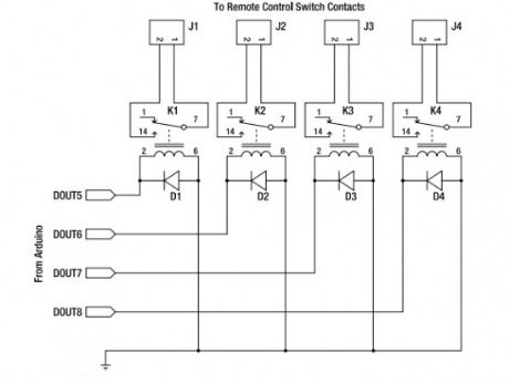
Starting from today I will try to post interesting Arduino projects from around the web. I am novice in this domain but I am giving my best to fully understant it. I must say from the begining that the projects are not developed by me and I will link the original source.
This Arduino project uses a general-purpose appliance remote control that you can buy from a hardware store. It can be modified to link it to an Arduino for software control of devices around your house, without having to touch any mains-level wiring.
Parts required:
1 Arduino Duemilanove, Arduino Pro, Seeeduino, or equivalent
1 RF appliance remote control
1 Prototyping shield
4 5V reed relays
4 1N4001 power diodes or similar
4 PCB-mount male connectors
4 line-mount female connectors
10 cm ribbon cable
Source: http://www.practicalarduino.com/projects/appliance-remote-control
?
One Response to “Appliance Remote Control Arduino Project”
(View)
View full Circuit Diagram | Comments | Reading(2024)
Simple soil moisture sensor – Arduino Project
Published:2012/9/24 4:15:00 Author:muriel | Keyword: soil, moisture, sensor

This is a simple arduino project for a soil moisture sensor that will light up a LED at a certain moisture level. It uses Arduino Duemilanove microcontroller board. Two wires placed in the soil pot form a variable resistor, whose resistance varies depending on soil moisture. This variable resistor is connected in a voltage divider configuration, and Arduino collects a voltage proportional to resistance between the 2 wires.Insert the 2 probes (wires, pcb) in the dry soil and measure the resistance value and then pour water and measure it again.Use a mid value for the resistor (eg: 50kΩ for 100kΩ in dry soil and 10kΩ in wet).
The other method to find the resistor’s value is to try different values or use a potentiometer. Insert the probes into the soil that has the desired moisture when to light up the LED and signal that the plant needs water.
Adjust the potentiometer and see the point at which it starts to light. Measure the potentiomenter current value and replace it with a fixed resistor.
Arduino soil moisture sensor schematic
Project source codeconst int VAL_PROBE = 0; // Analog pin 0
const int MOISTURE_LEVEL = 250; // the value after the LED goes ON
void setup() {
Serial.begin(9600);
}
void LedState(int state) {
digitalWrite(13, state);
}
void loop() {
int moisture = analogRead(VAL_PROBE);
Serial.println(moisture);
if(moisture > MOISTURE_LEVEL) {
LedState(HIGH);
} else {
LedState(LOW);
}
delay(100);
}
Source (romanian): http://www.tehnorama.ro/cum-sa-faci-o-floare-sa-te-traga-de-maneca-atunci-cand-ai-uitat-sa-o-uzi/?
2 Responses to “Simple soil moisture sensor – Arduino Project”
(View)
View full Circuit Diagram | Comments | Reading(2881)
| Pages:321/2234 At 20321322323324325326327328329330331332333334335336337338339340Under 20 |
Circuit Categories
power supply circuit
Amplifier Circuit
Basic Circuit
LED and Light Circuit
Sensor Circuit
Signal Processing
Electrical Equipment Circuit
Control Circuit
Remote Control Circuit
A/D-D/A Converter Circuit
Audio Circuit
Measuring and Test Circuit
Communication Circuit
Computer-Related Circuit
555 Circuit
Automotive Circuit
Repairing Circuit