
Circuit Diagram
Index 341
CAR STOP LIGHT
Published:2012/9/11 20:58:00 Author:Ecco | Keyword: CAR, STOP, LIGHT
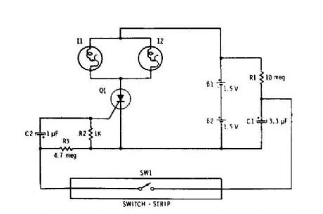
Capacitor Cl is connected continuously through the supply of 3 volts to 10 megohm resistor Rl. The capacitor is charged (relatively slowly) to 3 volts. The wink SWI is closed, it connects the charged capacitor (Cl) in series with C2 and R2. The capacitor C2 begins to charge, by placing a positive voltage during the gate of the SCR and turn it on. The two parallel self-flashing bulbs I1 and 12 on Tum. They flash on and off the SCR and the circuit is turned off until the vehicle is driven off the switch and C1 can recharge. (View)
View full Circuit Diagram | Comments | Reading(1806)
Model Glow Plag driver circuit
Published:2012/9/11 20:58:00 Author:Ecco | Keyword: Model , Glow Plag driver
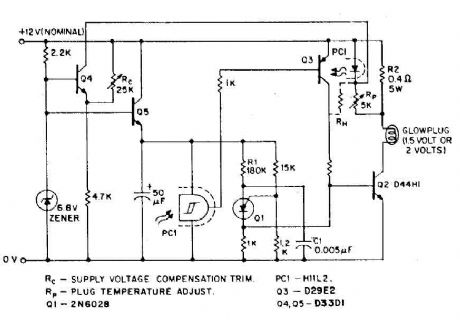
model airplanes, boats, cars and use of ignition of glow plugs for their miniature (O. Bcc to 15cc) internal combustion engines. These engines happen with the heavy batteries on board, HT coil, and condenser spark required for ignition classic, while simultaneously developing much higher RPM (and thus power) as the compression ignition (diesel) engines . The heart of a candle is a coil of platinum alloy filament heated to start the engine by an external battery, or 1. 5 volts or 2 volts. To complete this battery, a second power supply of 12 volts is often necessary to start the engine, together with a third type 6 volt electric fuel pump. (View)
View full Circuit Diagram | Comments | Reading(1867)
Car Exhaust Meter
Published:2012/9/11 20:57:00 Author:Ecco | Keyword: Car Exhaust, Meter
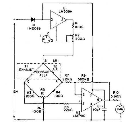
Bridge circuit contains two resistors lOO-ohm (R3 and R4), and two thermistors (Tl and T2). At room temperature, the resistance of T1 and 1'2 is about 2000 ohms. When they are each heated to 150 ° C by an RNA 10 current, the resistance value decreases to 100 ohms. So. the four elements include a bridge circuit. CO is a characteristic that conducts heat from a thermistor at a rate different from that of air. A thermistor, TI, is exposed to automobile exhaust, while the other, 1'2, is isolated in an environment of clean air. Unlike thermal conduction bridge imbalance. A voltage difference is caused between points A and C. A differential amplifier. VI, amplifies this difference and leads to the counter with a current sufficient to read the percentage of CO and air-fuel ratio. A control panel before the balance, R5, balances the bridge and calibrates the instrument. The calibration is performed when both thermistors are exposed to outside air. (View)
View full Circuit Diagram | Comments | Reading(2057)
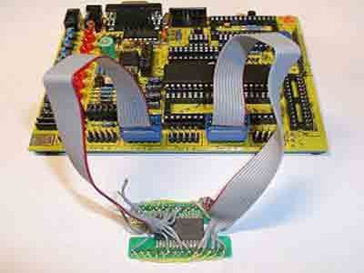
AVR-P40-USB-8535 BOARD FOR AT90S8535
Published:2012/9/11 20:52:00 Author:Ecco | Keyword: AVR-P40-USB-8535 BOARD
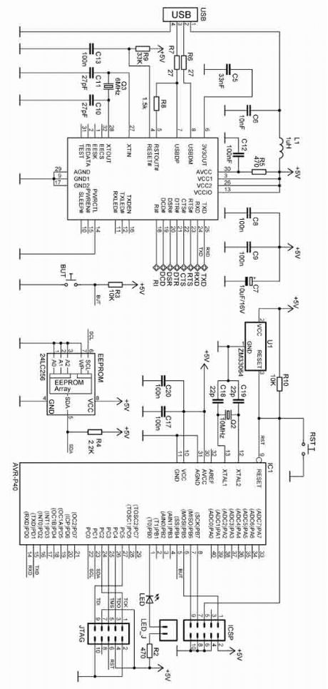
There are two ways to program AVR-P40-USB: with ICSP port and with JTAG port. To program via ICSP port you need serial port or parallel port AVR-ICSP programmer dongle (Olimex part # AVR-PG1B or AVR-PG2B). The serial port ICSP programmer (AVR-PG1B) works with PonyProg software by from Claudio Lanconelli and the latest release may be download for free from lancos.com The parallel port ICSP programmer (AVRPG2B) works with AVR ISP from Atmel and may be download for free from Atmels web site. (View)
View full Circuit Diagram | Comments | Reading(1395)
Wireless Keylogger circuit
Published:2012/9/11 20:52:00 Author:Ecco | Keyword: Wireless Keylogger
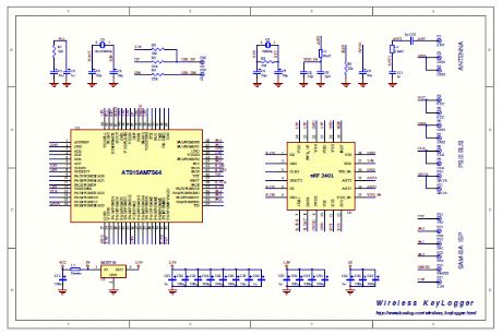
The Wireless Keylogger consists of two main building blocks: the transmitter, and the receiver. The actual keylogging takes place in the transmitter, which is in fact a PS/2 hardware keylogger, with a built-in 2.4 GHz wireless module. Captured keystroke data is transmitted through the radio-link in real-time, rather than getting stored. The receiver on the other hand, is a wireless acquisition unit with a USB interface. All keystroke data received from the transmitter is sent to the host computer via USB. From the software side, this data is available through a virtual COM port, allowing any terminal client to be used for visualizing keystroke data. (View)
View full Circuit Diagram | Comments | Reading(3221)
Display board to interface it with 8051
Published:2012/9/11 20:51:00 Author:Ecco | Keyword: Display board, interface
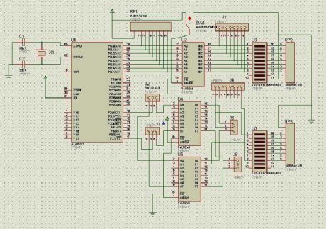
74hc573 is used to store data so that the previous content on SS is not vanish when we disable LE pin. T0 select the proper latch 74hc238, 3x8 decoder is used. And to convert BCD into decimal, 74ls48 converter is used. Note that latches U1 to U4 are connected with C.C SS, so the output of 74ls48 will only go to these latches. Whereas latches U6 and U8 are connected to DP oF SS and LEDs respectfully. You can emit these latches i used them to distinguish between various mode i.e, digital clock, stop watch, counter and manual input. (View)
View full Circuit Diagram | Comments | Reading(2681)
Interfacing DS1307 RTC AVR Microcontroller
Published:2012/9/11 20:51:00 Author:Ecco | Keyword: Interfacing, RTC , AVR Microcontroller
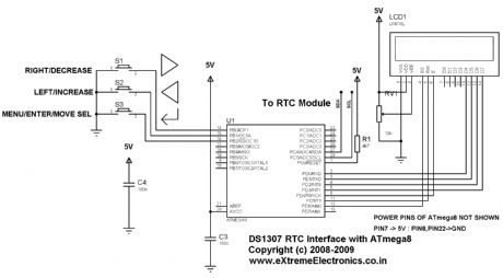
Real Time Clocks, as the name suggests are clock modules. They are available as integrated circuits (ICs) and manages timing like a clock. Some RTC ICs also manages date like a calendar. The main advantage is that they have a system of battery backup which keeps the clock/ca lender running even in case of power failure. A very small current is required for keeping the RTC alive. This in most case is provided by a miniature 3v lithium coin cell. So even if the embedded system with RTC is powered off the RTC module is up and running by the backup cell. This same technique is used in PC timing also. If you have opened your computer case you will notice a small coin cell in the mother board. (View)
View full Circuit Diagram | Comments | Reading(2292)
Frequency counter 400Hz to 50MHz with PIC 16F84
Published:2012/9/11 20:49:00 Author:Ecco | Keyword: Frequency counter , 400Hz to 50MHz , PIC
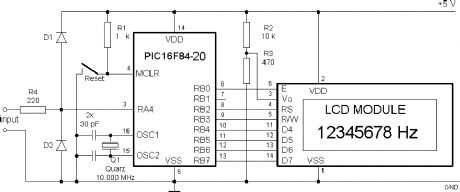
It consists only from Microchip PIC 16F84 cpu and LCD text module. Author states that this counter is capable metering frequencies from 400Hz to 50MHz. I used faster, 20MHz version of 16F84A-20I/P, and it managed to count 80MHz oscillator output. (View)
View full Circuit Diagram | Comments | Reading(7548)
AVR Microcontroller Digital Clock with ATtiny 2313
Published:2012/9/11 20:32:00 Author:Ecco | Keyword: AVR Microcontroller, Digital Clock , ATtiny
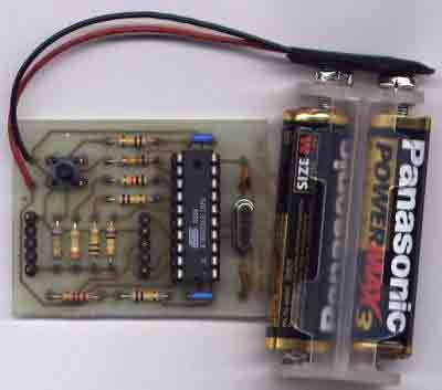
Usually we see Digital clock on LCD or 7 segmen. But, this AVR Digital Clock which is designed by Ficara Emilio displayed on Oscilloscope. The project use ATtiny 2313 as the main controller. What an interesting microcontroller project. Source code and schematic available for download. (View)
View full Circuit Diagram | Comments | Reading(2485)
LCD Oscilloscope using AVR MC
Published:2012/9/11 20:32:00 Author:Ecco | Keyword: LCD Oscilloscope, AVR MC
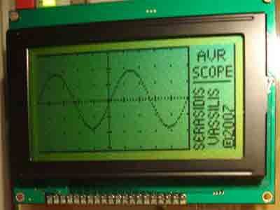
This is one of great project based on AVR microcontroller. It use ATmega 32 as processor and LCD 128x64 pixels for display. If you need to measure low frequency i thought this project, AVR oscilloscope, will be usefull. Maksimum frequency for AVR oscilloscope is 5 kHz (square signal), other signals (sine or triangle) the frequency is lower ( almost 1 kHz) for having clear view of the signal. Voltage input range is 24V AC / 30V DC. (View)
View full Circuit Diagram | Comments | Reading(4840)
Interfacing DRAM M5M44800 Memory with AVR AT90S8515
Published:2012/9/11 20:30:00 Author:Ecco | Keyword: Interfacing DRAM, Memory , AVR
Is it possible to use DRAM with microcontroller AVR? Yes, it is possible. Jesperh has proved it. He hooked up a DRAM to a small processor (in this case an Microcontroller Atmel 8515), and handle the RAS/CAS sequencing and refresh in software. The type of DRAM is Hitatchi M5M44800, a 512k*8 DRAM!. Bigger than the original memory of microcontroller AT90S8515 that is 512 byte RAM. The project use C to programm it. The chip required small power consumption, only takes about 2-3 mA when just refreshing and with a low access rate. (View)
View full Circuit Diagram | Comments | Reading(1271)
4 microphones mixer circuit with TL081
Published:2012/9/11 20:29:00 Author:Ecco | Keyword: 4 microphones , mixer
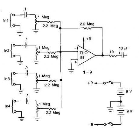
A TL081 op amp is used as a high impedance to low. converter and a signal mixer. The input impedance is about 1 megohm and the output impedance is about 1 kohm. Two 9 volt batteries are used as power source. (View)
View full Circuit Diagram | Comments | Reading(0)
Fully adjustable preamplifier
Published:2012/9/11 20:28:00 Author:Ecco | Keyword: Fully adjustable , preamplifier
This circuit is a audio preamplifier tha has balance, tone and loudness controls. It should be suitable as an example of good design for audio application. Uses the BAA730 and NE540 chips. (View)
View full Circuit Diagram | Comments | Reading(0)
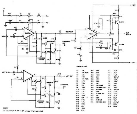
Stereo Preamplifier with balance and loudness
Published:2012/9/11 20:27:00 Author:Ecco | Keyword: Stereo Preamplifier , balance , loudness
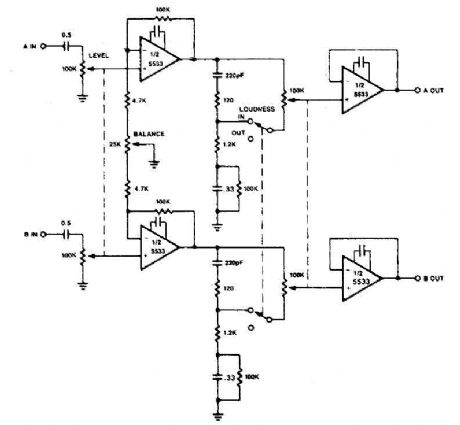
The circuit of preamplifier use the 5533 chip and features a combination of controls balance and volume. Due to the nonlinearity of the human auditory system, low frequencies must be boosted at low listening levels. Level pay, and LOUDNESS controls provide all the plays to produce the desired response from the music. (View)
View full Circuit Diagram | Comments | Reading(0)
Attenuator circuit
Published:2012/9/11 20:27:00 Author:Ecco | Keyword: Attenuator
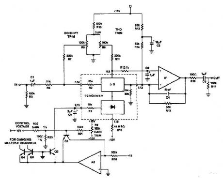
A op amp and transistors Q1 and Q2 exponential converter to generate an exponential gain control current, which is introduced into the rectifier. A reference current of 150 pA, (15 V and RZO = lOO-k), is attenuated by a factor of two (6 dB) for each increase of tension in the control voltage. Capacitor C6 slows secure changes to a period of 20 IDS constant (C6 x IR) such that a sudden change in the control voltage will produce a gain change smooth sound. RI8 ensures that for control voltages of the circuit will go to great attentuation full. (View)
View full Circuit Diagram | Comments | Reading(1324)
Simple differential amplifier circuit
Published:2012/9/11 20:26:00 Author:Ecco | Keyword: Simple, differential amplifier
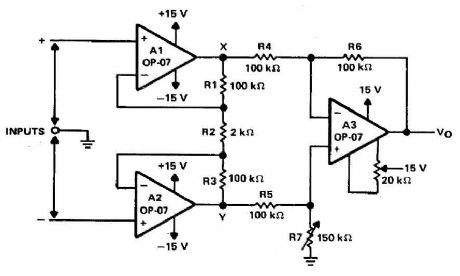
Operational amplifiers Al and A2 are connected in a noninverting configuration of their training sorties amplifier A3. The operational amplifier A3-one could call a subtractor circuit that converts the differential signal between the floating point X and Y in a single ended output voltage . Although not mandatory, amplifier A3 is usually used in unity gain and R4, R5, R6, and R7 are all equal. Joining-rejection of the amplifier A3 is a function of how the rate of R4: R5 R6 is the ratio: R7. For example, when using resistors with a tolerance of 0.1%, common mode rejection exceeds 60 dB. further improvement can be achieved by using a potentiometer (slightly higher than the value of R6) to R7. (View)
View full Circuit Diagram | Comments | Reading(3326)
Input pulse width controller circuit
Published:2012/9/11 20:26:00 Author:Ecco | Keyword: Input pulse, width controller
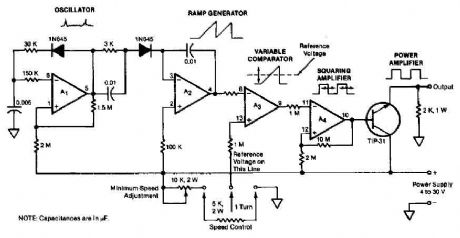
The quad operational amplifier circuit yields full 0 to 100 percent pulse width control. The controller uses an LM3900 requires only a single supply voltage of 4-30 V. The pulse repetition frequency is set by a 1 kHz oscillator amplifier that integrates AI. The oscillator feeds the Az ramp generator, which generates a linear ramp voltage for each pulse oscillator. The ramp signal feeds the inverting input of comparator A3, the control voltage feeds speed non-inverting input. Thus, the output of the comparator is a 1 kHz pulse train, pulse width that changes linearly with control voltage. (View)
View full Circuit Diagram | Comments | Reading(1839)
Audio splitter amplifier circuit with TL084
Published:2012/9/11 20:26:00 Author:Ecco | Keyword: Audio, splitter , amplifier
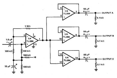
The three-channel amplifier output distribution uses a single TL084. The first step is to capacitive coupling with a p. 1.0 ~ electrolytic capacitor. The entries are railways Vee Y2 or 4.5 V. This allows using a single 9 V power supply A voltage gain of 10 (1 M ohm ohm/l00 k) is obtained in the first stage, and the other three floors are connected as a unity gain voltage followers. Each output stage drives independently via an amplifier output 50 pF capacitor to the resistance of 5.1 k ohm load. (View)
View full Circuit Diagram | Comments | Reading(7946)
Headphone Amplifier circuit
Published:2012/9/11 20:25:00 Author:Ecco | Keyword: Headphone , Amplifier
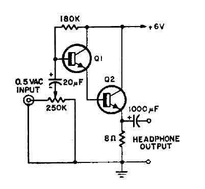
This is a simple headphone amplifier. You can use any NPN transistor. (View)
View full Circuit Diagram | Comments | Reading(4077)
Bell circuit with two 555 timers
Published:2012/9/11 20:20:00 Author:Ecco | Keyword: Bell, two 555 timers
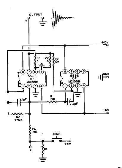
This simple Bell circuit uses two 555 timers. The frequency is controlled by the capacitors that must be preserved almost identical in value to each other for best results. Fine tuning is done with R1 and R2. (View)
View full Circuit Diagram | Comments | Reading(1443)
| Pages:341/2234 At 20341342343344345346347348349350351352353354355356357358359360Under 20 |
Circuit Categories
power supply circuit
Amplifier Circuit
Basic Circuit
LED and Light Circuit
Sensor Circuit
Signal Processing
Electrical Equipment Circuit
Control Circuit
Remote Control Circuit
A/D-D/A Converter Circuit
Audio Circuit
Measuring and Test Circuit
Communication Circuit
Computer-Related Circuit
555 Circuit
Automotive Circuit
Repairing Circuit