
Circuit Diagram
Index 357
Single-way flashing light string circuit (3)
Published:2012/8/30 21:38:00 Author:Ecco | Keyword: Single-way, flashing light string
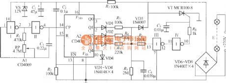
As shown in the figure, it is a single-way flashing controller composed of digital IC, it can make the light string flash continuously in the cycle of strong light → stronger → weak light → turning off → highlight ... ... , the flashing is no longer dull, but full of freshness. And it only has two leading-out terminals which can be directly connected to the colored light string circuit in series, and it is convenience to wire and use.
(View)
View full Circuit Diagram | Comments | Reading(902)
Single-switch multi-light control circuit (1)
Published:2012/8/30 21:59:00 Author:Ecco | Keyword: Single-switch, multi-light, control
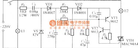
As shown in the figure, it only uses a light switch to control two groups of bulbs E1 and E2. Firstly, S is closed, E1 is lit, E2 is not lit; after S disconnects, the lamp is turned off; if S is closed again in short time (about 0.5~3s), E1 and E2 will be lit at the same time; if S disconnecting time is longer, S is closed again, that is equivalent to first closing of S.
(View)
View full Circuit Diagram | Comments | Reading(1013)
Dual-way flashing light string circuit with music (MC81P)
Published:2012/8/31 2:02:00 Author:Ecco | Keyword: Dual-way , flashing light string, music
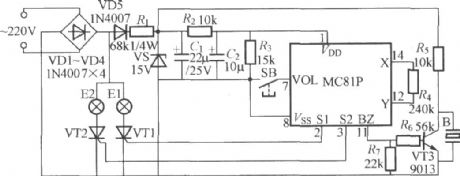
As shown in the figure, it is a novel flashing light string controller for Christmas tree decorations, it has two-way flashing output with storing 6 songs, and it is characterized by alternately synchronized flashing of two string lights with music rhythm, and it uses buttons to control the sound of music and the skipping of light. VT1 and VT2 can choose 0.8~1A/400~600V small plastic one-way thyristor such as 2N6565, MCR100-8; b is Piezoelectric ceramic speaker or 27mm common Piezoelectric ceramic plate.
(View)
View full Circuit Diagram | Comments | Reading(1243)
Four-way flashing light string circuit with music (CS9802)
Published:2012/8/31 1:20:00 Author:Ecco | Keyword: Four-way , flashing light string, music
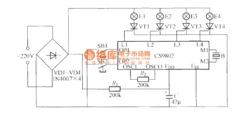
As shown in the figure, it is a four-way flashing light stringcontroller with music, and its core component is the CS9802 music colouredlantern control IC.
(View)
View full Circuit Diagram | Comments | Reading(1027)
Text-display logic pen (CD4069) circuit diagram with gate circuit
Published:2012/8/30 22:35:00 Author:Ecco | Keyword: Text-display , logic pen , gate circuit
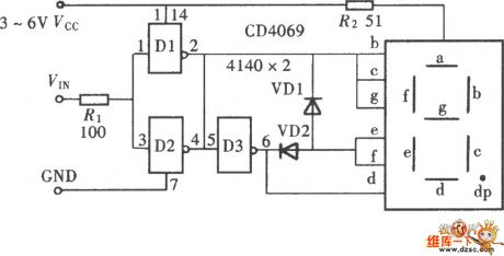
The text-display logic pen is shown in the figure, the text here does not mean high and low in Chinese, but the word h and l in English. Due to the particularity of this two-letter glyphs, you can easily use it to form logic level test with LED digital tube.
(View)
View full Circuit Diagram | Comments | Reading(2891)
LM378 24 V DC Proportional Motor Speed Control
Published:2012/9/3 3:14:00 Author:Ecco | Keyword: 24 V DC , Proportional, Motor , Speed Control
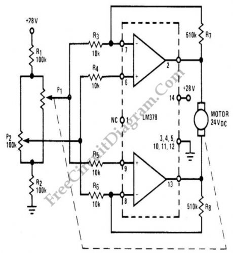
National LM378 amplifier is used as a basis for economical proportional motor speed controller. This integrated circuit is able to deliver 700 mA continuous current for such DC motor applications such as antenna rotors or motor controlled valves. The basic of proportional control is as simple as amplifying the error signal to produce an action in such direction that minimize the error. This error signal is generated by a mechanically coupled potentiometer wired in a Wheatstone bridge R1-R2-P1-P2 configuration. The potentiometer P1 is coupled to the motor shaft to sense the actual speed of the motor, act as continuous feedback sensor. (Source: freecircuitdiagram)
(View)
View full Circuit Diagram | Comments | Reading(2927)
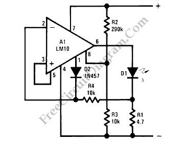
Logarithmic Light Intensity Meter for Photography
Published:2012/9/3 3:12:00 Author:Ecco | Keyword: Logarithmic, Light Intensity Meter, Photography
Using LM10 amplifier and voltage reference, a light intensity meter featured with five decades dynamic range (which is suitable for photographic application) can be built. Please note that the linear to log conversion is not temperature compensated, and can make 40% error (a half stop in photography) at the worst point of conversion slope at ±18°C temperature drift. It should be noted that silicon photodiode is sensitive to near-infrared wavelength, while ordinary films are not. Filtering out the infrared using infrared-stop filter or using blue-enhanced photodiode will improve the performance.(Source: freecircuitdiagram)
(View)
View full Circuit Diagram | Comments | Reading(1174)
Battery Level Indicator
Published:2012/9/3 3:10:00 Author:Ecco | Keyword: Battery Level, Indicator
A battery level indicator circuit is depicted in the schematic diagram below. This circuit is designed for 9V battery operation, as this circuit will start dimming below 7V and will be completely turned off at 6V. If you want the LED indicator not to dimming but just abruptly turns off at below 6V, then you can remove R3, and change R1 to 330k. (Source: freecircuitdiagram)
(View)
View full Circuit Diagram | Comments | Reading(2272)
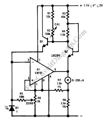
LM134-LM10 Thermometer/Temperature Sensor
Published:2012/9/3 3:08:00 Author:Ecco | Keyword: Thermometer, Temperature Sensor
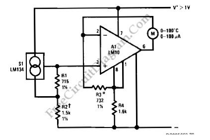
Using LM134 and LM10 integrated circuits, we can build a thermometer which has -55 to 150°C sensing range. The ideal meter for this circuit is a 0-200uA digital ampere meter, which can show both positive and negative polarity. This will make the circuit suitable for indicating temperatures below 0°C. LM134 is basically a current source with very accurate and consistent temperature coefficient, so many temperature sensing application find it suitable for the sensor. Here is the schematic diagram of the circuit: (Source: freecircuitdiagram)
(View)
View full Circuit Diagram | Comments | Reading(2451)
555 IC Hysteresis for Dark Activated Relay
Published:2012/9/3 3:06:00 Author:Ecco | Keyword: 555 IC , Hysteresis , Dark Activated Relay
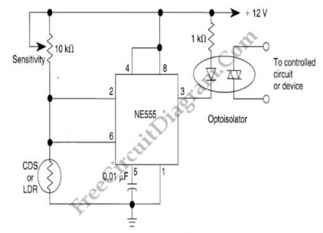
In the relay’s point of view, dark activated means the relay will be activated when the light intensity fall below a certain threshold. Without hysteresis, the relay will be activated and deactivated if the sensed brightness fall under or rise above a single point of darkness level. With hysteresis, the darkness level for activating and deactivating the relay will be different, and this solve the relay oscillation problem when the light intensity is swinging up and down around a single point of no hysteresis activation level.
We can employ the hysteresis of a 555 IC to improve the sensing of a drop in light, since the internal 555 circuit has 1/3 and 2/3 supply voltage thresholds. We have to use a LDR or CDS cell with aout 2 to 8 k resistance at desired light level. At the dark, the resistance of the LDR will rise and activate the relay if the voltage at pin 2 reach 2/3 of supply voltage (8V). After the relay is activated, more light is needed to make the LDR decrease its resistance until the voltage at pin 2 falls below 1/3 supply voltage (4V). (Source: freecircuitdiagram)
(View)
View full Circuit Diagram | Comments | Reading(2796)
Low Power Under- and Over-Voltage Monitor
Published:2012/9/3 3:03:00 Author:Ecco | Keyword: Low Power, Under-voltage , Over-Voltage, Monitor
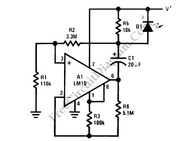
This voltage monitor has two threshold, VTH for undervoltage and VTH’ for overvoltage. Using the component values shown in the schematic diagram below, this circuit give 6V for VTH and 15V for VTH1. Above 6V, the LED indicator of this voltage monitor circuit will increase the flash rate until reach 15V. This circuit will stop flashing at voltage below 6V and above 15 volts since there will be no current flowing through C1. At threshold boundary, the output of LM10 will saturate to negative below VTH and saturate to positive above VTH’.
To customize circuit we can select the resistors values according to chosen VTH and VTH’ using the following formula:
VTH=[R4(R1+R2)Vref]/[R1(R3+R4)];
VTH’=[R4(R1+R2)Vref]/[R1(R3+R4)-R3(R1+R2)]
Since the current consumption is very small (around 500uA), this voltage monitor will be suitable for various application demanding low cost solution, such as battery monitoring, small testing equipments, or power line indication.(Source: freecircuitdiagram)
(View)
View full Circuit Diagram | Comments | Reading(2)
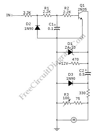
General Purpose Alarm Circuit for Resistive Sensor
Published:2012/9/3 3:01:00 Author:Ecco | Keyword: General Purpose, Alarm Circuit , Resistive Sensor
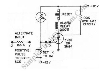

When the resistance value of a temperature, light, pressure, or any other resistive sensors Rs drops below a certain point (adjusted by a preset potentiometer), the SCR (silicon controlled switch) will be triggered. The sensor (Rs) and the potentiometer placement can be interchanged to get opposite action, where the SCR need to be triggered at the increase of sensing resistor (Rs). Here is the schematic diagram of the circuit: (Source: freecircuitdiagram)
(View)
View full Circuit Diagram | Comments | Reading(989)
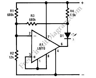
LM10 Battery Voltage Threshold Indicator
Published:2012/9/3 2:47:00 Author:Ecco | Keyword: Battery , Voltage Threshold, Indicator
A battery threshold indicator circuit shown in the schematic diagram below has current regulation mechanism in driving the LED. A sufficient current should be satisfied at the minimum voltage but no excessive current when the voltage is at the highest level. Balance pin (5) is used as the reference voltage for regulating the current. This pin generate 23 mV, which is internally temperature compensated.
This battery voltage threshold indicator circuit overcomes the difficulties caused by voltage change across the diode biasing resistor.
When the voltage on the reference-feedback terminal (8) drops below 200 mV, the reference output (1) rises to supply the feedback voltage to the op amp through D2, so the LED current drops to zero. The minimum threshold voltage for these circuits is basically imited by the bias voltage for the LEDs. Typically, this is 1.7V for red, 2V for green and 2.5V for yellow. These two circuits can be made to operate satisfactorily for threshold voltages as low as 2V if a red diode is used. (Source: freecircuitdiagram)
(View)
View full Circuit Diagram | Comments | Reading(2024)
Touch Switch Monostable/Timer with 555 IC
Published:2012/9/3 2:45:00 Author:Ecco | Keyword: Touch Switch , Monostable, Timer , 555 IC
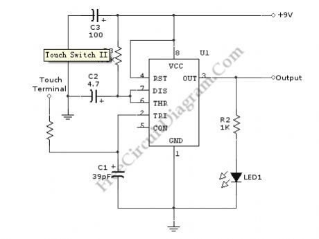
Using the given values as shown in the schematic diagram, this circuit has timed ON period of 4 seconds. The value of C2 and R3 determines the ON time, increasing the value of C2 or R3 will increase the ON time. The ON time is decreased if the value of C2 or R3 is decreased.
A schematic diagram of a touch switch circuit is shown below. This circuit consist of timer, one shoot multivibrator and touch terminal. As timer, this circuit uses 555 timer which is connected to one-shot multivibrator. The touch terminal is used to trigger this circuit. The output of this circuit can be used to drive a power transistor, CMOS circuitry, hexFET transistor or optocoupler. Here is the schematic diagram of the touch switch circuit: (Source: freecircuitdiagram)
(View)
View full Circuit Diagram | Comments | Reading(2721)
Logic Power Control for 78xx Regulator
Published:2012/9/3 2:43:00 Author:Ecco | Keyword: Logic , Power Control , Regulator
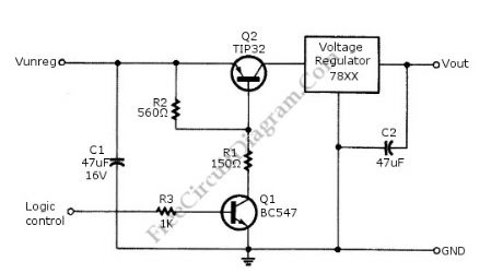
Logic power control of analog regulator can be useful in application where a digital circuit/controller need to control power source, such as in EEPROM programmer or other power controls. This is a circuit provide ON-OFF control for 78xx regulator using digital (TTL or CMOS) signal level. This circuit uses transistors in series with the 78XX regulator, which it’s base is controlled by logic level input. Here is the schematic diagram of the circuit: (Source: freecircuitdiagram)
(View)
View full Circuit Diagram | Comments | Reading(1)
Sound-Controlled Relay
Published:2012/9/3 2:38:00 Author:Ecco | Keyword: Sound-Controlled, Relay

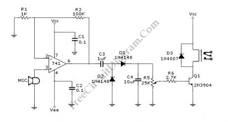
This is a relay circuit that detect the presence of sound to activate the relay. You can use this sound-controlled relay as voice operated switch, light control, toys, or any other application that can be controlled by a switch. Just replace the switch with this relay and now you have a sound-controlled device. This circuit uses a 741 operational amplifier to amplify the signal form microphone with the gain about 100 times. This circuit must use a dynamic circuit, or an electret microphone which has a battery inside. A condenser microphone can’t be used since this circuit has no biasing circuitry.
After the signal from microphone is amplified, a rectifier-doubler circuit built with D1 and D2 convert the AC signal to DC. After rectified, the AC ripple is filtered by C4 capacitor to smooth the signal. Finally, a potentiometer R5 is used to adjust the sensitivity of this circuit, calibrating the point of how loud the sound would turn on the relay.
Here is the schematic diagram of the circuit: (Source: freecircuitdiagram)
(View)
View full Circuit Diagram | Comments | Reading(1437)
Tachometer Circuit with Single Transistor
Published:2012/9/3 2:35:00 Author:Ecco | Keyword: Tachometer , Single Transistor


A schematic diagram of simple tachometer circuit is shown below. Using only a single transistor as the active component, this tachometer would probably be the simplest one. The input of this circuit can be picked up from ignition pickup coil, or other wiring that gives ignition wave-form. This tachometer circuit works for 0 to 6,000 rpm. R3 is used for calibrating the full scale meter reading, to get valid rpm. The zener diode D1 is used to stabilize the 12-V supply. Here is the schematic diagram of the circuit: (Source: freecircuitdiagram)
(View)
View full Circuit Diagram | Comments | Reading(1462)
Strobed Supply Improves Strain Gauge Bridge Efficiency
Published:2012/9/3 2:32:00 Author:Ecco | Keyword: Strobed Supply , Improves, Strain Gauge Bridge , Efficiency
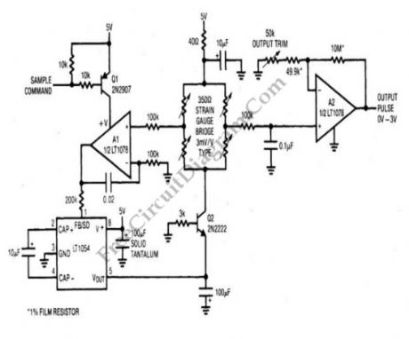
The following schematic diagram shows a method to reduce power consumption without sacrificing the bridge signal output level of a strain gauge. Many situation will be applicable for this strain gauge bridge signal conditioning circuit, where continuous output is not a must. In the long time frame, this circuit will in idle state for almost all the time, with only intermittent quick active states (on times). A very extreme example for this signal conditioning circuit is where remote weight or height level of a storage tanks is sampled once per hour. The idle current is around 150 μA, with active state current typically 50 mA (which is occurs at few milliseconds periods). (Source: freecircuitdiagram)
(View)
View full Circuit Diagram | Comments | Reading(978)
One Direction Motion Sensor
Published:2012/9/3 2:31:00 Author:Ecco | Keyword: One Direction, Motion, Sensor

This is a one direction motion sensor circuit. This motion sensor circuit is used to detects an object passing in one direction, ignoring an object that going to opposite way. This circuit uses two sensors to identify the movement only in one direction. The basic principle of this circuit is simple, where one sensor is used to generate a short pulse, and the other sensor is used to block of turn of the gate. The phototransitors give high output on their collectors when there is an object blocking the light. By a 0.4uF differentiator capacitor, the interruption of light at Q2 sensor will produce short pulse at point C. But this short pulse will only appear at the output if a high signal appears at A. This condition will be satisfied if the light to Q1 is blocked by the object when the object is passing through Q2, means that the direction should be from Q1 to Q2. Here is the schematic diagram of the circuit:(Source: freecircuitdiagram)
(View)
View full Circuit Diagram | Comments | Reading(1940)
Digital Encoder Circuit Using Stepper Motor
Published:2012/9/3 2:20:00 Author:Ecco | Keyword: Digital Encoder , Stepper Motor
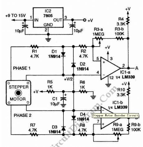
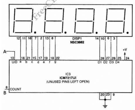
Using circuit depicted in the schematic diagram below, the direction and shaft rotation of stepper motor can be seen on the LED display. Alternative to digital rotation encoder as a digital encoder input, this circuit uses a stepper motor. Here is the schematic diagram of the circuit: (Source: freecircuitdiagram)
(View)
View full Circuit Diagram | Comments | Reading(3991)
| Pages:357/2234 At 20341342343344345346347348349350351352353354355356357358359360Under 20 |
Circuit Categories
power supply circuit
Amplifier Circuit
Basic Circuit
LED and Light Circuit
Sensor Circuit
Signal Processing
Electrical Equipment Circuit
Control Circuit
Remote Control Circuit
A/D-D/A Converter Circuit
Audio Circuit
Measuring and Test Circuit
Communication Circuit
Computer-Related Circuit
555 Circuit
Automotive Circuit
Repairing Circuit