
Circuit Diagram
Index 346
Four-way flashing light string circuit ( 3 )(LC182)
Published:2012/9/9 22:58:00 Author:Ecco | Keyword: Four-way , flashing light string
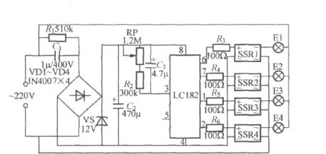
As shown in the figure, it is high-power four-way flashing light string controller using LC182. The LC182 Manifold contains rectifier amplifier, voltage-controlled oscillator and timing pulse divider, when the circuit is energized, the pin ⑥ ⑦ ① and ② appear high level in a cycle, and the circulation rate depends on the voltage-controlled oscillator's oscillation frequency. Changing pin ③ external rescap or changing audio signal from the internal rectifier amplifier input end of pin ⑤, its voltage-controlled oscillation frequency can be adjusted. SSR1 ~ SSR4 can use SP110 solid state relay, and the maximum output current is up to 3A.
(View)
View full Circuit Diagram | Comments | Reading(1173)
Reflected Infrared Light Switch
Published:2012/9/9 21:20:00 Author:Ecco | Keyword: Reflected , Infrared Light, Switch
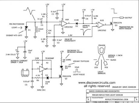
Infrared light reflected off a finger is used to activate this switch circuit. Drawing only 30uA from a 3v supply, this circuit will detect a human finger with a range of about 1 inch. The sensor uses an inexpensive infrared LED and a matching photo diode.
Source: discovercircuits (View)
View full Circuit Diagram | Comments | Reading(2187)
5 VOLT MOMENTARY OPERATION TOUCH SWITCH
Published:2012/9/9 21:19:00 Author:Ecco | Keyword: 5 VOLT, MOMENTARY OPERATION , TOUCH SWITCH
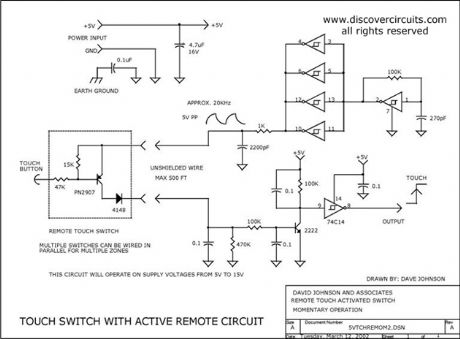
This simple circuit uses a single IC to form a nice touch switch circuit. A single transistor forms the remote active switch sensor. Multiple switches can be wired in parallel. The switch circuit can be located about 500 feet from the control circuit.
Source: discovercircuits (View)
View full Circuit Diagram | Comments | Reading(0)
Home Made Geophone Detects Foot Stomp
Published:2012/9/9 21:17:00 Author:Ecco | Keyword: Home Made, Geophone, Detects, Foot Stomp
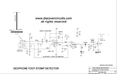
A home made geophone is made from a strong magnet, a coil of wire and a rubber band. The circuit is sensitive enough to detect the vibrations of a nearby foot stomp. It could be used as an earthquake detector.
Source: discovercircuits (View)
View full Circuit Diagram | Comments | Reading(5527)
CMOS INVERTER PARALLEL LC OSCILLATOR
Published:2012/9/9 21:15:00 Author:Ecco | Keyword: CMOS , INVERTER , PARALLEL , LC OSCILLATOR
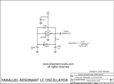
I have used this parallel resonant LC oscillator circuit countless times. The oscillator frequency is determined by the inductor and capacitor values. I have shown an adjustable inductor to make it easy to set the frequency to a specific value. Once set the frequency is fairly stable over supply voltage variations and temperature changes. The values shown are for 125KHz but the frequency can range from tens of kilohertz to tens of megahertz. With a 74HCU04 type inverter, it will oscillate down to about 1.5 volts. If the frequency is low, you can also use a 74C04 (CD4069) inverter.
Source: discovercircuits (View)
View full Circuit Diagram | Comments | Reading(3967)
PRECISION FULLWAVE RECTIFIER
Published:2012/9/9 21:13:00 Author:Ecco | Keyword: PRECISION, FULLWAVE RECTIFIER
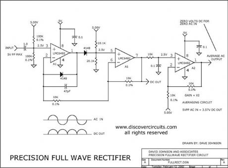
I have used this handy circuit many times. It accurately converts an AC signal into pulsing DC, which can be filtered to provide an average of the input voltage. It works from millivolts to volts. The circuit shown requires a stable +5v reference if a single power supply is used.
Source: discovercircuits (View)
View full Circuit Diagram | Comments | Reading(3108)
Circuit Forms Ideal Diode Function
Published:2012/9/9 21:13:00 Author:Ecco | Keyword: Circuit Forms , Ideal , Diode Function

This circuit uses a low power op amp and a p-channel FET to form a diode function with a very low 0.05 volt voltage drop. With the selected FET, the circuit can handle up to 2 amps of current. Higher currents are possible with a FET with a lower channel resistance. The total current drawn by the circuit during operation is a low 20 microamps. The maximum voltage is 15v.
Source: discovercircuits (View)
View full Circuit Diagram | Comments | Reading(3496)
175KHz INDUCTIVE PULSE TRANSMITTER
Published:2012/9/9 21:10:00 Author:Ecco | Keyword: 175KHz , INDUCTIVE, PULSE TRANSMITTER

This circuit is discussed in more detain in the Experimenters Journal. The transmitter?s six-inch diameter coil launches powerful magnetic 175KHz ring pulses that can be detected by the circuit below.
Source: discovercircuits (View)
View full Circuit Diagram | Comments | Reading(1243)
Infrared Safety Switch
Published:2012/9/9 21:09:00 Author:Ecco | Keyword: Infrared , Safety Switch
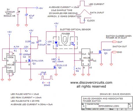
Using a slotted optical sensor, this circuit can be used as a replacement for a large mushroom pushbutton safety switch.
Source: discovercircuits (View)
View full Circuit Diagram | Comments | Reading(2331)
12v Battery Load Cutout Circuit -- August 23, 2009
Published:2012/9/9 21:08:00 Author:Ecco | Keyword: 12v, Battery Load, Cutout Circuit

Lead-acid batteries should not be discharged below a certain point if they are to last. Also, you don?t want certain 12v powered devices, which might be plugged into a car?s cigarette lighter outlet, to drain the car battery down to a point where the car?s engine will not start. To prevent battery damage or a dead battery, the circuit below disconnects a load from the battery when the voltage dips below a fixed but adjustable voltage and will not reconnect the load until a reset button is pressed. To keep the whole circuit efficient and compact, a medium current rated p-channel FET forms the power switch. A 8.2v zener diode forms the voltage reference while a second 15v zener diode acts as a transient voltage protector.
Source: discovercircuits (View)
View full Circuit Diagram | Comments | Reading(1325)
Miniature 5v Line Powered Isolated Supply
Published:2012/9/9 21:05:00 Author:Ecco | Keyword: Miniature 5v , Line Powered, Isolated Supply

Often a circuit requires a 5v DC supply to power some logic circuits. The conventional method is to use an AC wall adapter. But, many systems, which bring AC power onto a circuit board, need a small AC to DC power supply right on the circuit board. The circuit below provides such a supply. It uses a classic series capacitor charge pump which acts as a current limiting device.
Source: discovercircuits (View)
View full Circuit Diagram | Comments | Reading(3466)
SOLID STATE RELAY REQUIRES ONLY 50uA DRIVE CURRENT
Published:2012/9/9 21:04:00 Author:Ecco | Keyword: SOLID STATE, RELAY , REQUIRES, ONLY 50uA , DRIVE CURRENT

This circuit demands a control current that is 100 times smaller than that needed by a typical optically isolated solid state relays. It is ideal for battery-powered systems. Using a combination of a high current TRIAC and a very sensitive low current SCR, the circuit can control about 600 watts of power to load while providing full isolation and transient protection.
Source: discovercircuits (View)
View full Circuit Diagram | Comments | Reading(1107)
OPTICAL INTERRUPTER DRAWS MICROAMPS
Published:2012/9/9 21:03:00 Author:Ecco | Keyword: OPTICAL, INTERRUPTER, DRAWS MICROAMPS
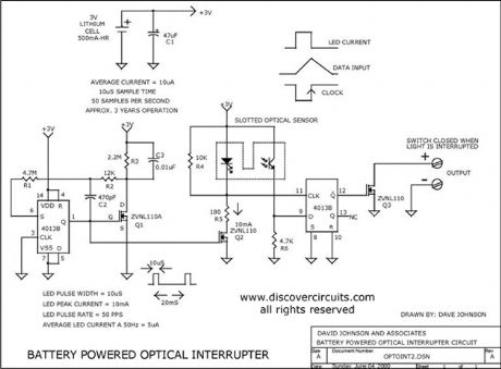
This circuit is great for battery-powered systems that use slotted type optical interrupters. It draws only 10uA from a 3v battery that should allow up to 5 years of operation from a lithium battery.
Source: discovercircuits (View)
View full Circuit Diagram | Comments | Reading(3014)
LINE POWERED XENON FLASH TRANSMITTER
Published:2012/9/9 21:02:00 Author:Ecco | Keyword: LINE POWERED , XENON FLASH , TRANSMITTER

This line powered xenon flash circuit drives a small camera type flash tube. It has an optical isolator to allow the flash to be safely triggered from some remote device. A flash rate of 2Hz is possible with the circuit.
Source: discovercircuits (View)
View full Circuit Diagram | Comments | Reading(4371)
Very Loud 3v Powered Beeper -- August 16, 2009
Published:2012/9/9 21:00:00 Author:Ecco | Keyword: Very Loud , 3v, Powered Beeper

Getting a high sound intensity from a piezoelectric type beeper is not easy when the available DC supply is only 3v. The circuit below is not only efficient but produces a very intense sound. The circuit combines a voltage boost section with a resonant feedback network. The voltage applied to the piezoelectric wafer is about 40 volts peak to peak. The result is a circuit that generates an attention getting sound without drawing a lot of current.
Source: discovercircuits (View)
View full Circuit Diagram | Comments | Reading(994)
AUDIO FREQUENCY DIGITAL NOISE GENERATOR
Published:2012/9/9 20:56:00 Author:Ecco | Keyword: AUDIO FREQUENCY, DIGITAL , NOISE GENERATOR

When you need to test an audio circuit with broadband noise, this circuit works great. It uses just three inexpensive C-MOS ICs that generate a series of output pulses whose widths vary randomly. I included a level control pot.
Source: discovercircuits (View)
View full Circuit Diagram | Comments | Reading(0)
PRECISION AC PEAK DETECTOR
Published:2012/9/9 20:55:00 Author:Ecco | Keyword: PRECISION, AC PEAK , DETECTOR
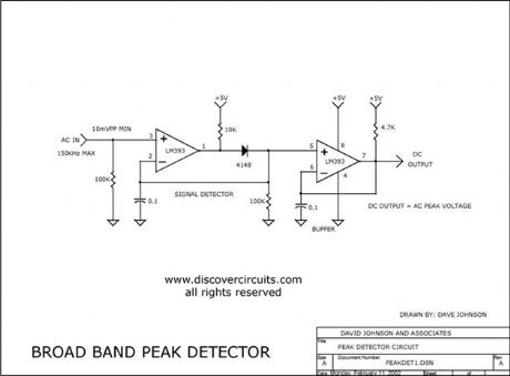
This unique circuit uses a very inexpensive voltage comparator to form a peak detector. The DC voltage produced tracks the positive peak of the input signal. It works from about ten millivolts to about 10 volts peak to peak. The maximum frequency is about 150KHz.
Source: discovercircuits (View)
View full Circuit Diagram | Comments | Reading(5201)
Reduced Power Relay Driver
Published:2012/9/9 20:54:00 Author:Ecco | Keyword: Reduced Power , Relay Driver

Relays can handle a lot of power. However, for certain power sensitive designs you would like to reduce the power needed to hold a relay closed. The circuit below performs such a task. It uses a single CD4093 quad NAND gate. When the ?on? logic input signal is detected, the relay is first pulsed on for about 500ms. This is sufficient time to insure the relay is fully closed. After that initial pulse the relay is then driven with a square wave signal, whose duty cycle can be adjusted. The signal duty cycle can be adjusted from about 10% to 90%. In most cases a 50% duty cycle will hold the relay closed. This reduces the average DC current required by the same factor, which means a 4:1 reduction in power. The circuit can operate over a wide 3v to 15v range.
Source: discovercircuits (View)
View full Circuit Diagram | Comments | Reading(745)
VOLTAGE TO FREQUENCY CONVERTER + 1uS LED PULSE DRIVER
Published:2012/9/9 20:54:00 Author:Ecco | Keyword: VOLTAGE TO FREQUENCY CONVERTER , + 1uS , LED PULSE DRIVER
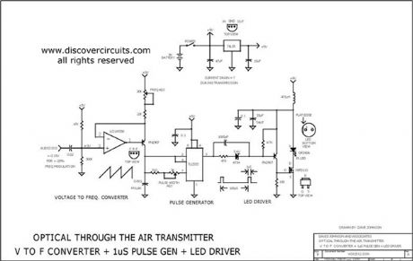
This circuit receives the signal from the above amplifier and launches powerful 1uS infrared light pulses from a low cost LED that are frequency modulated by the audio information. The 10KHz center frequency of the pulse stream is low enough so a standard infrared LED can emit ten times more light than conventional long pulse techniques. The circuit is described in more detail in the transmitter section of my Handbook of Optical Through the Air Communications.
Source: discovercircuits (View)
View full Circuit Diagram | Comments | Reading(2891)
Ultra Low Current Oscillator (February 17, 2009)
Published:2012/9/9 20:51:00 Author:Ecco | Keyword: Ultra Low Current, Oscillator

Here is a challenge. Design an astable oscillator which draws only a few nanoamps of current from a +3v supply. I gave this some thought and came up with the circuit below. I used some pretty standard parts except for three surface mounted 1000M resistors I had on hand. The oscillator frequency measured a low 1Hz frequency and the average current was a very low 3 nanoamps. If I had some higher resistors values handy, I think I could have gotten the current down below one nanoamp.
Source: discovercircuits (View)
View full Circuit Diagram | Comments | Reading(1682)
| Pages:346/2234 At 20341342343344345346347348349350351352353354355356357358359360Under 20 |
Circuit Categories
power supply circuit
Amplifier Circuit
Basic Circuit
LED and Light Circuit
Sensor Circuit
Signal Processing
Electrical Equipment Circuit
Control Circuit
Remote Control Circuit
A/D-D/A Converter Circuit
Audio Circuit
Measuring and Test Circuit
Communication Circuit
Computer-Related Circuit
555 Circuit
Automotive Circuit
Repairing Circuit